Instructions manual / BTP
6
Do not store the machine and battery pack in locations
where the temperature may reach or exceed 50oC
(122oF).
Do not incinerate the battery pack even if it is severely
damaged or completely worn out. The battery pack can
explode in a fire.
Be careful not to drop, shake, or strike the battery.
Do not charge inside a box or container of any kind. The
battery must be placed in a well ventilated are during
charging.
Do not dispose of battery packs into household waste,
fire or water. Battery packs should be collected,
recycled or disposed of in an environmentally-friendly
manner. Call the authorized warranty centers for places
to dispose of damaged or inoperable batteries.
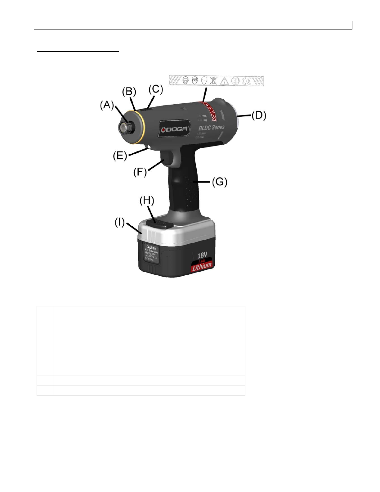
3. FUNCTIONAL DESCRIPTION
This industrial shut off screwdriver is designed for nut
tightening/loosening and screw driving/loosening. It is
not appropriate to use for wood/mild steel drilling.
Please refer to the figure on the page to familiarize
yourself with the major components of this tool before
use.
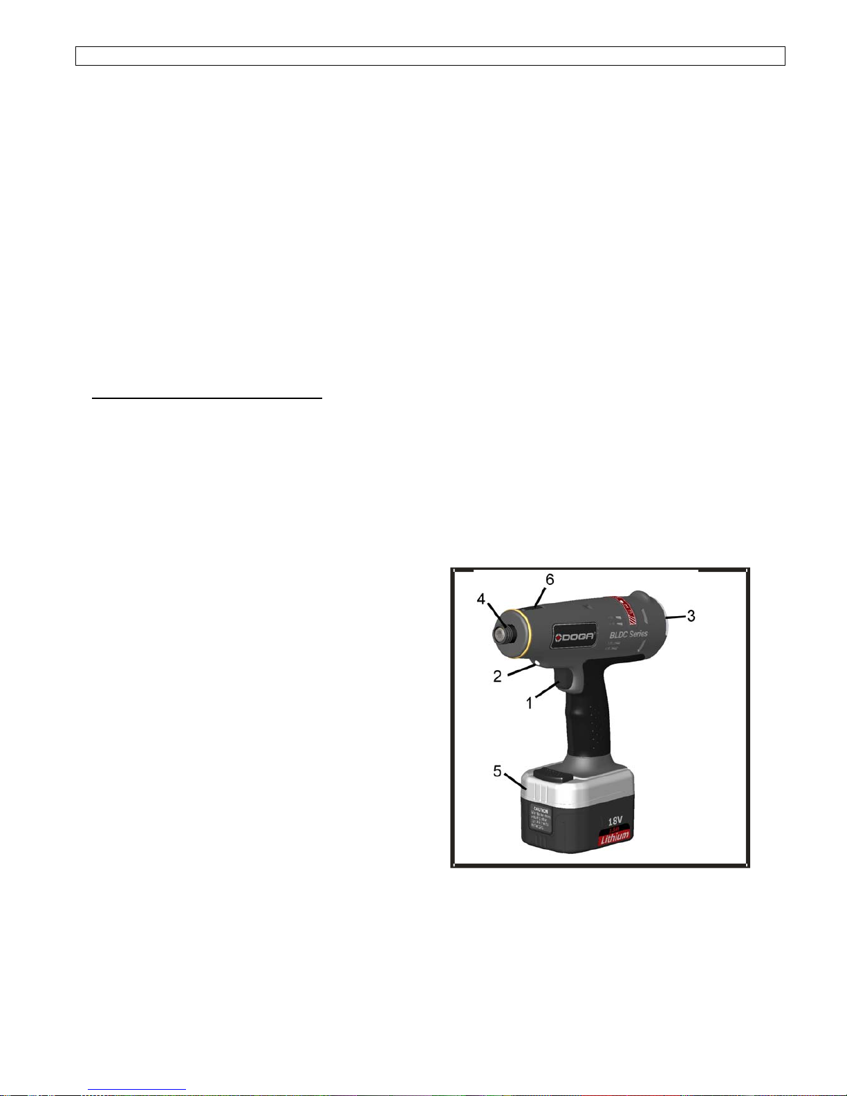
1. Power Switch
Depressing the power switch will energize the LED
light (2) in front and the tool starts to rotate. When
released, power to the motor will cease and the tool
stops to work immediately. But the LED light will
remain for 10 seconds then off.
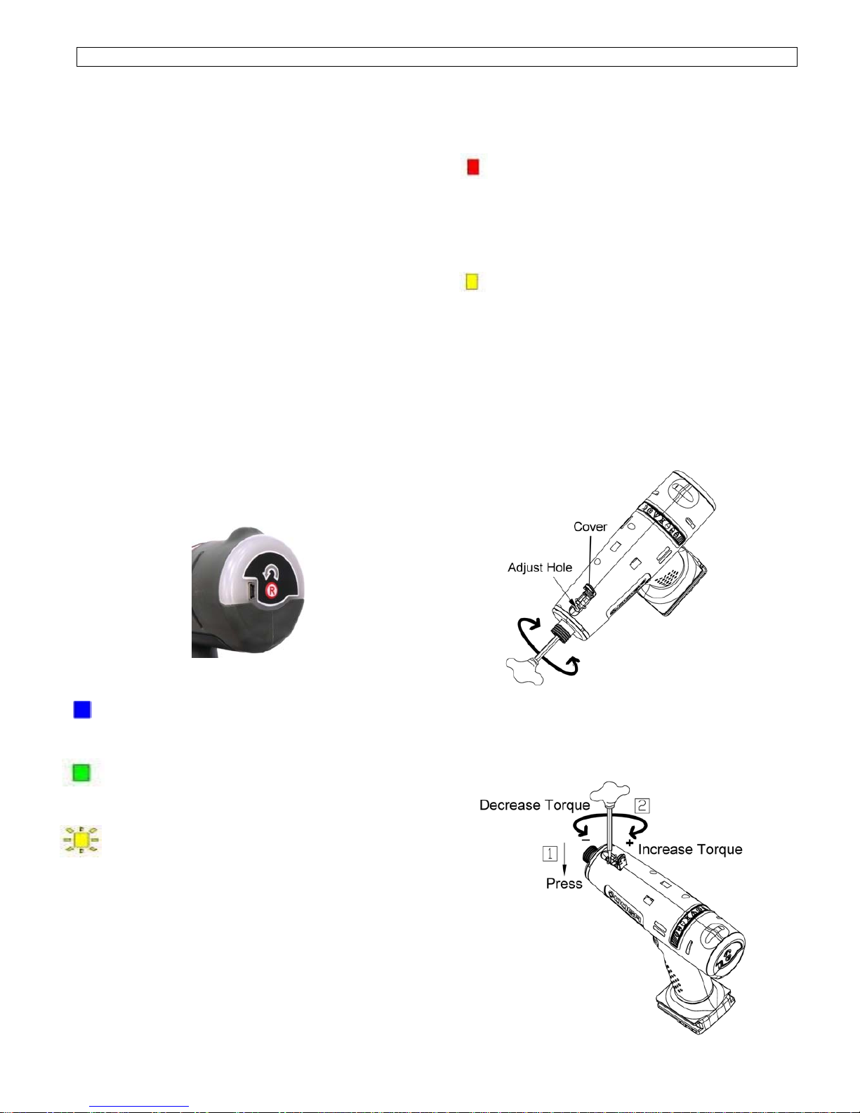
3. Forward/Reverse Button
The tool is always in forward operation unless the
Forward/Reverse button is pressed. When the
button is pressed, the blue LED shows and the
tool will be in reverse operation. To get the tool
back in forward operation, just simply press the
button again and the blue LED would disappear
and the tool is back in forward operation.
4. Quick Change Holder
This driver accepts only 1/4” (6.35mm) hexagonal
bits. Be sure the bit is fully engaged by the chuck
before operating tool. Otherwise, the bit may fly off
and cause property damage or personal injury.
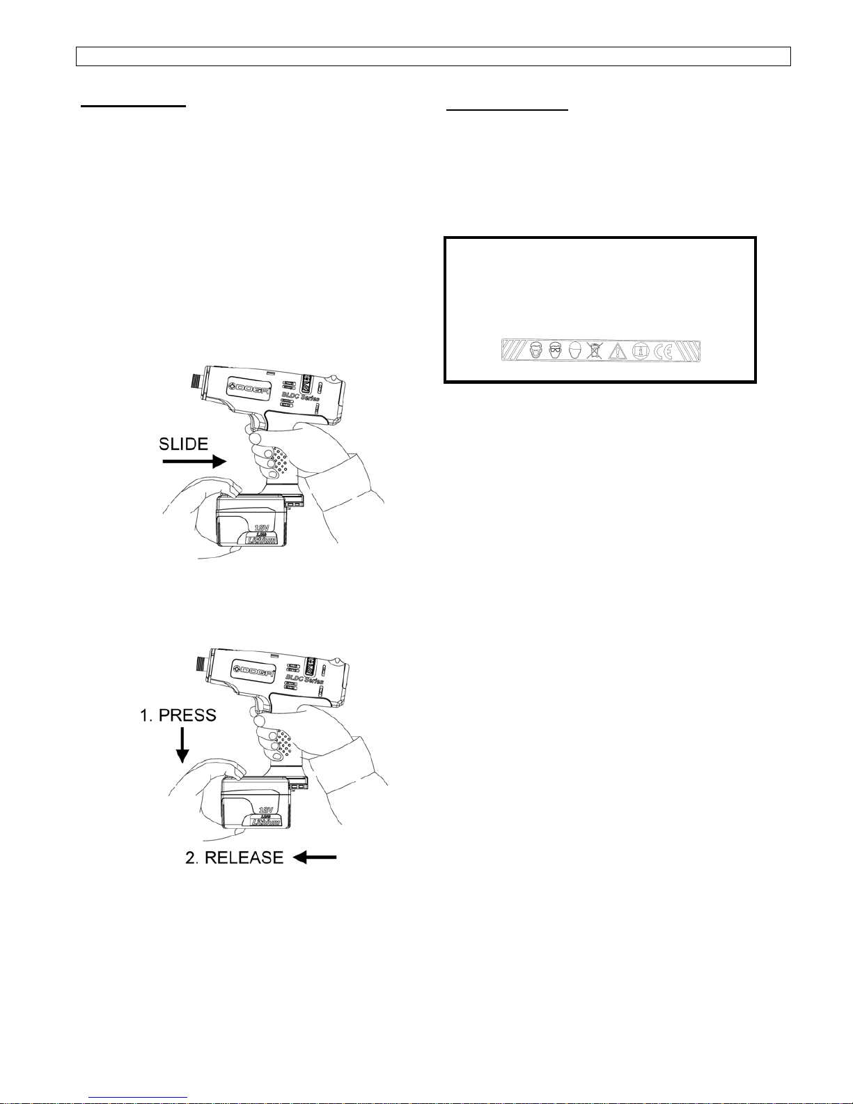
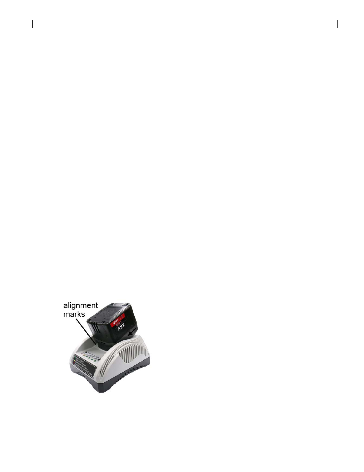
5. Li-ion Battery
This battery provides electrical power to the
motor. Please charge it according to the charging
instruction listed in this manual.
6. Torque Adjustment Cover
Open the torque adjustment cap. Use the torque
adjustment tool to either tighten or loosen the
spring until the desired torque is reached.
WARNING: Use the tool to either tighten or loosen
nuts and screws ONLY in stipulated torque and
voltage ranges.