Seiko Epson S5U13781R00C10M User manual

Rev.1.2
S5U13781R00C10M
User Manual
Document Number: X94A-G-008-01.2

2 Seiko Epson Corporation S5U13781R00C10M User Manual
(Rev.1.2)
Evaluation board/kit and Development tool important notice
1. This evaluation board/kit or development tool is designed for use for engineering evaluation,
demonstration, or development purposes only. Do not use it for other purpose. It is not intended to meet
the requirement of design for finished product.
2. This evaluation board/kit or development tool is intended for use by an electronics engineer, and it is not a
consumer product. The user should use these goods properly and safely. Seiko Epson dose not assume any
responsibility and liability of any kind of damage and/or fire caused by usage of it. The user should cease
to use it when any abnormal issue occurs, even during proper and safe use.
3. The parts used for this evaluation board/kit or development tool may change without notice.
NOTICE
No part of this material may be reproduced or duplicated in any form or by any means without the written
permission of Seiko Epson. Seiko Epson reserves the right to make changes to this material without notice.
Seiko Epson does not assume any liability of any kind arising out of any inaccuracies contained in this material
or due to its application or use in any product or circuit and, further, there is no representation that this material
is applicable to products requiring high level reliability, such as, medical products. Moreover, no license to
any intellectual property rights is granted by implication or otherwise, and there is no representation or
warranty that anything made in accordance with this material will be free from any patent or copyright
infringement of a third party. When exporting the products or technology described in this material, you should
comply with the applicable export control laws and regulations and follow the procedures required by such
laws and regulations. You are requested not to use, to resell, to export and/or to otherwise dispose of the
products (and any technical information furnished, if any) for the development and/or manufacture of weapon
of mass destruction or for other military purposes.
All brands or product names mentioned herein are trademarks and/or registered trademarks of their respective
companies.
©SEIKO EPSON CORPORATION 2012-2018. All rights reserved.

S5U13781R00C10M User Manual Seiko Epson Corporation 3
(Rev.1.2)
Table of Contents
1Introduction......................................................................................................................... 5
2LCD Module Options and Parts Lists .................................................................................. 7
3Connecting the Boards........................................................................................................ 8
4StellarisWare Drivers and Demo Software.........................................................................11
4.1 Requirements..............................................................................................................................11
4.1.1 Hardware Requirements .....................................................................................................11
4.1.2 Software Requirements.......................................................................................................11
4.2 Software Installation....................................................................................................................11
4.3 Software Description...................................................................................................................13
4.3.1 Driver Software....................................................................................................................13
4.3.2 Demonstration Software......................................................................................................14
4.4 Software Modification..................................................................................................................14
4.5 Software License.........................................................................................................................14
5MSP430Ware Drivers and Demo Software........................................................................15
5.1 Requirements..............................................................................................................................15
5.1.1 Hardware Requirements .....................................................................................................15
5.1.2 Software Requirements.......................................................................................................15
5.2 Software Installation....................................................................................................................15
5.3 Software Description...................................................................................................................17
5.3.1 Driver Software....................................................................................................................17
5.3.2 Demonstration Software......................................................................................................18
5.4 Software Modification..................................................................................................................18
5.5 Software License.........................................................................................................................18
6MSP430 / Stellaris LM4F120 Launchpad Connections.......................................................19
7Pinout for 40-Pin LCD Interface .........................................................................................21
8Pinout for 54-Pin LCD Interface .........................................................................................23
9S5U13781M00C100 Schematics.......................................................................................27
10 S5U13781M00C100 Board Layout.....................................................................................31
11 Change Record..................................................................................................................35
12 Sales and Technical Support .............................................................................................36

4 Seiko Epson Corporation S5U13781R00C10M User Manual
(Rev.1.2)

Introduction
S5U13781R00C10M User Manual Seiko Epson Corporation 5
(Rev.1.2)
1 Introduction
The S5U13781R00C10M is the S1D13781 BoosterPack LCDC Development Package. It is a
BoosterPack board set for TI’s MSP430 and Stellaris LM4F120 Launchpad for evaluating and developing
embedded LCD display applications using the Epson S1D13781 LCD Controller IC.
The S5U13781R00C10M consists of the following two items:
•S5U13781R00C100 Reference Board Set
•S5U13781M00C100 Signal Adapter Board Set
Figure 1 shows a picture of the S5U13781R00C100 Reference Board Set.
Figure 1 –S5U13781R00C100 Reference Board Set
The S5U13781R00C100 Reference Board Set consists of two break-off sub-boards:
•Main board which has the S1D13781 LCD Controller, 2Mbytes of Serial Flash, DC/DC converter
for LED backlight, 2x25 connector for Host interface (J4), and 2x25 connector for LCD interface
(J5).
•LCD interface board which has a 54-pin FPC (flexible printed circuit) connector (J8) to connect
to LCD module and 0.1”-pitch 2x25+2x6 connectors (J9 and J10).
For more information about the S5U13781R00C100, please refer to the “S5U13781R00C100 Reference
Board User Manual”, document number X94A-G-004-01

Introduction
6 Seiko Epson Corporation S5U13781R00C10M User Manual
(Rev.1.2)
Figure 2 shows a picture of the S5U13781M00C100 Signal Adapter Board Set.
Figure 2 –S5U13781M00C100 Signal Adapter Board Set
The S5U13781M00C100 Signal Adapter Board Set is a supplement to the S5U13781R00C100 Reference
Board Set and it consists of three break-off sub-boards (schematics and layout are in Sections 9 and 10):
•“Board A –Host Interface Adapter”is used to adapt the S5U13781R00C100 Main Board’s Host
Interface signals (P5) to the MSP430 or Stellaris LM4F120 Launchpad BoosterPack connectors
(P1 to P4), and it also routes the S5U13781R00C100 Main Boards’ LCD Interface signals (P9) to
a connector (J2) for connecting to either “Board B – LCD Signal Adapter –40Pin” or “Board C –
LCD Signal Adapter –54Pin”.
•“Board B –LCD Signal Adapter –40Pin”provides signal routing for connecting to an LCD
module with a 40-pin FPC (4.3” WQVGA). One side (PB1) connects to J2 of Board A and the
other side (PB2) connects to J9 of the S5U13781R00C100 LCD interface board.
•“Board C –LCD Signal Adapter –54Pin”provides signal routing for connecting to an LCD
module with a 54-pin FPC (3.5” QVGA). One side (PC1) connects to J2 of Board A and the
other side (PC2+PC3) connects to J9+J10 of the S5U13781R00C100 LCD interface board.
This user manual is updated as appropriate. Please check the Seiko Epson Website at
http://www.epson.jp/device/semicon_e/product/lcd_controllers/index.htm for the latest revision of this
document before beginning any development.
We appreciate your comments on our documentation. Please contact us via email at
vdc-docum[email protected].
LCD Module Options and Parts Lists
S5U13781R00C10M User Manual Seiko Epson Corporation 7
(Rev.1.2)
2 LCD Module Options and Parts Lists
The S5U13781R00C10M development package can interface to two types of LCD modules. One type of
LCD module has a 40-pin FPC interface (4.3” WQVGA display) and the other type has a 54-pin FPC
interface (3.5” QVGA).
The boards in the S5U13781R00C10M package do not come with any header/receptacle connectors
installed. These connectors will have to be purchased separately and soldered to the boards by the end-
user.
The following table shows the two LCD module options and their parts list (with manufacturer part
numbers):
40-Pin Interface
54-Pin Interface
Manufacturer Part Number
S5U13781R00C10M
1
1
Epson S5U13781R00C10M
2x25, 0.1”-pitch header
4
4
3M 961250-6404-AR
2x25, 0.1”-pitch receptacle
4
4
3M 929975-01-25-RK
2x10, 0.1”-pitch receptacle
2
2
3M 929975-01-10-RK
2x3, 0.1”-pitch header
-
1
3M 929836-01-03-RK
2x3, 0.1”-pitch receptacle
-
1
3M 929975-01-03-RK
54-Pin, 3.5”, QVGA LCD
-
1
Newhaven Display
NHD-3.5-320240MF-ATXL#-1 or
Hantronix HDA351-LV
Evervision VGG322425-6UFLWA or
Topway LMT035KDH03 or
Tianma TM035KDH03 or
All Shore ASI-T-350EA3NN/D or
Powertip PH320240T-006-I-Q or
Ampire AM320240L2TMQW-TB0H or
Logic Tech. LTTD320240035-L1RT or
US Micro USMP-TT035Q-01D or
Tech Toys LVC75Z779V2S or
Microtips MTF-TQ35SP741-AV
40-Pin, 4.3”, WQVGA LCD
1
-
Newhaven Display
NHD-4.3-480272EF-ATXL#(-T) or
All Shore ASI-T-430FA6NT/H or
AZ Displays ATM0430D5(-T) or
Logic Tech. LTTD480272043-L1 or
Tianma TM043NBH02
NOTE: The MSP430 or Stellaris LM4F120 Launchpad board is not included in the parts list and will
have to be purchased separately if the end-user does not already have one.

Connecting the Boards
8 Seiko Epson Corporation S5U13781R00C10M User Manual
(Rev.1.2)
3 Connecting the Boards
Figure 3 shows the board connections diagram (side view) for the S5U13781R00C10M BoosterPack
LCDC Development Package.
Figure 3 –Board Connections Diagram
The Stellaris LM4F120 Launchpad board has 2x10 headers on the top side for J1/J3 and J2/J4. The
MSP430 Launchpad has headers for connection to J1 and J2 only.
J8 of the S5U13781R00C100 LCD Interface Board is an FPC connector with bottom side contacts. The
FPC of the LCD module should be inserted into J8 with contacts facing down and pin 1 lined up with the
pin 1 edge of J8 (see Figure 4).
Figure 4 –J8 FPC Connection Example for 40-Pin LCD Module
J1
(Side View)
J3
J2
J4
MSP430 or Stellaris LM4F120
Launchpad Board
S5U13781R00C100
Main Board
S5U13781M00C100
Board A
LCD Module
P1
P3
P4
P2
P5
P9
J4
J5
PB1 or
PC1
S5U13781M00C100
Board B or
Board C
PB2 or
PC2
PC3
S5U13781R00C100
LCD Interface Board
J10
J9
J8
J2
J8 Pin 1
FPC Pin 1
(contacts face down)

Connecting the Boards
S5U13781R00C10M User Manual Seiko Epson Corporation 9
(Rev.1.2)
STEPS FOR ASSEMBLING S5U13781R00C10M DEVELOPMENT PACKAGE
Modification to Stellaris LM4F120 Launchpad Board
1) On the Stellaris LM4F120 Launchpad board, remove (de-solder) resistors R9 and R10. This
disconnects the short-circuits between GPIO ports PB6/PD0 and PB7/PD1.
Soldering of Header and Receptacles
2) On the S5U13781R00C100 Main Board, connect pins 3 and 4 of J3 (solder a wire across the two
pins or solder a header with shunt jumper) to set the current of the backlight LED driver to 20mA.
The Newhaven 3.5” display is rated at 20mA typical and the Newhaven 4.3” display is rated at
32mA typical. (Current drive can be increased in steps of 20mA by shorting pins 5-6 and pins 7-
8 of J3.)
3) On the S5U13781R00C100 Main Board, connect pins 1 and 2 of J1 (solder a wire across the two
pins or solder a header with shunt jumper) to connect power for the Serial Flash.
4) On the bottom side of the S5U13781R00C100 Main Board, install and solder 2x25 headers for
J4 and J5.
5) On the top side of the S5U13781M00C100 Board A, install and solder 2x25 receptacles for P5
and P9.
6) On the bottom side of the S5U13781M00C100 Board A, install and solder 2x10 receptacles for
P1+P3 and P2+P4. (Note that P1 and P3 together make up one 2x10 receptacle and P2 and P4
together make up the other 2x10 receptacle.)
7) On the bottom side of the S5U13781M00C100 Board A, install and solder a 2x25 header for J2.
8) For a 40-pin (4.3”, WQVGA) LCD module, use S5U13781M00C100 Board B and install (on the
top side) 2x25 receptacles for PB1 and PB2. For a 54-pin (3.5”, QVGA) LCD module, use
S5U13781M00C100 Board C and install (on the top side) 2x25 receptacles for PC1 and PC2 as
well as a 2x3 receptacle for PC3.
9) On the bottom side of the S5U13781R00C100 LCD Interface Board, install and solder a 2x25
header for J9. If using a 54-pin LCD module, a 2x3 header for J10 should also be installed and
soldered on the bottom side of the S5U13781R00C100 LCD Interface Board.

Connecting the Boards
10 Seiko Epson Corporation S5U13781R00C10M User Manual
(Rev.1.2)
Assembly of Boards
10) Plug the bottom receptacles (P1 to P4) of S5U13781M00C100 Board A to the MSP430 or
Stellaris LM4F120 Launchpad headers. Make sure the pin 1s of P1-P4 (P1-P2) of
S5U13781M00C100 Board A line up with pin1s of J1-J4 (J1-J2) of the Stellaris LM4F120
(MSP430) Launchpad.
11) Plug the bottom headers (J4, J5) of S5U13781R00C100 Main Board to the top side receptacles
(P5, P9) of S5U13781M00C100 Board A. Make sure the pin 1s of J4 and J5 of the
S5U13781R00C100 Main Board line up with the pin1s of P5 and P9 of S5U13781M00C100
Board A.
12) Plug the 2x25 receptacle (PB1/PC1) of S5U13781M00C100 Board B/C to J2 (2x25 header) on
the bottom side of S5U13781M00C100 Board A. Make sure pin 1 of J2 of S5U13781M00C100
Board A lines up with pin 1 of PB1/PC1 of S5U13781M00C100 Board B/C.
13) Plug the bottom headers (J9, J10) of the S5U13781R00C100 LCD Interface Board to the top
side receptacles (PB2/PC2, PC3) of S5U13781M00C100 Board B/C.
14) Connect the LCD module’s FPC to J8 of the S5U13781R00C100 LCD Interface Board. Make
sure the pads/contacts side of the FPC are facing down and pin 1 of the FPC lines up with the pin
1 edge of J8 (please refer to Figure 4).

StellarisWare Drivers and Demo Software
S5U13781R00C10M User Manual Seiko Epson Corporation 11
(Rev.1.2)
4 StellarisWare Drivers and Demo Software
The S1D13781 BoosterPack LCDC Development Package was developed with a companion software
package (S5U13781R00C10M BoosterPack Software Package) that is available from the Epson website
at vdc.epson.com. This software package includes a S1D13781 demonstration application and graphics
library driver software source code intended for use in combination with TI StellarisWare and the
Stellaris LM4F120 Launchpad.
4.1 Requirements
4.1.1 Hardware Requirements
The S5U13781R00C10M BoosterPack Software Package was developed for use with the following
hardware.
•Stellaris LM4F120 Launchpad
•S5U13781R00C10M
•Compatible LCD Display
For details on preparing the hardware for use, see Section 3.
4.1.2 Software Requirements
The S5U13781R00C10M BoosterPack Software Package was developed for use with the following
software tools.
•Code Composer Studio –see http://www.ti.com/tool/ccstudio
•StellarisWare –see http://www.ti.com/stellaris
•ICDI USB drivers (for debugging) –see http://www.ti.com/tool/stellaris_icdi_drivers
4.2 Software Installation
The following steps are required to install the S5U13781R00C10M BoosterPack Software Package and
the required software tools. If the TI software tools have already been installed, skip to step 4.
Note:
The following instructions assume a PC running Windows XP (or higher). For compatibility with other
operating systems or development platforms, please refer to TI’s website at http://www.ti.com/stellaris.
1. Install the Code Composer Studio IDE.
2. Install StellarisWare
3. Connect the Launchpad to the PC via a USB connector. When prompted, install the Stellaris ICDI
drivers. On some systems, the drivers must be manually installed using the Windows Device
Manager.
4. Extract the S5U13781R00C10M BoosterPack Software Package ZIP file into the StellarisWare
working folder for the Launchpad board model being used (i.e. C:/StellarisWare/boards/ek-
lm4f120xl/).
5. Open Code Composer Studio.
StellarisWare Drivers and Demo Software
12 Seiko Epson Corporation S5U13781R00C10M User Manual
(Rev.1.2)
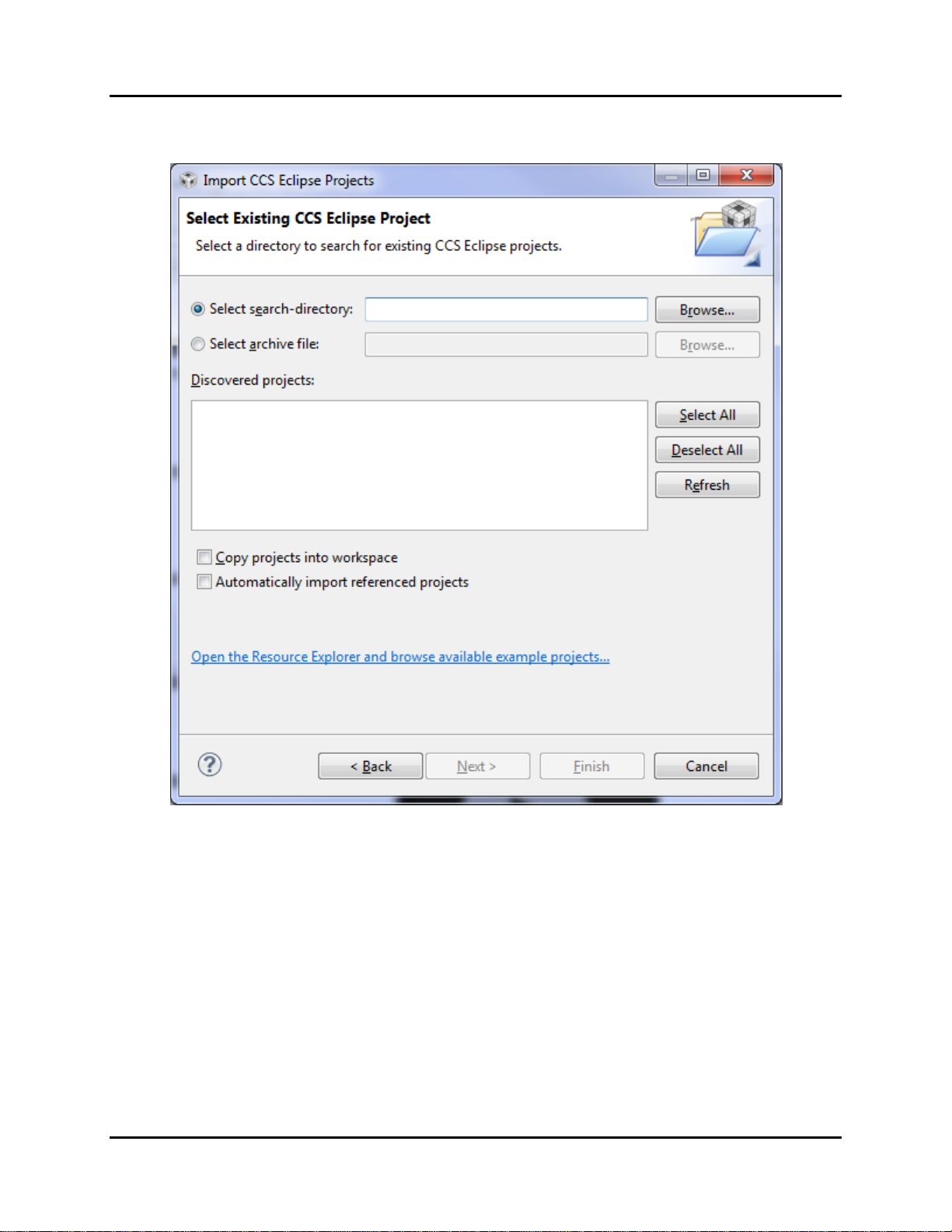
6. Select Import Project from the TI Resource Explorer or Import… > Code Composer Studio >
Existing CCS Eclipse Projects from the File Menu. The following window will appear.
7. Browse to the folder where the S5U13781R00C10M BoosterPack Software Package is installed
(i.e. C:/StellarisWare/boards/ek-lm4f120xl/BoosterPack_S1D13781/) and click OK.
8. The s1d13781_demo project should now be shown in the “Discovered Projects” list. Select
s1d13781_demo and click Finish.
9. The s1d13781_demo project should now be listed in the CCS Project Explorer.

StellarisWare Drivers and Demo Software
S5U13781R00C10M User Manual Seiko Epson Corporation 13
(Rev.1.2)
4.3 Software Description
The S5U13781R00C10M BoosterPack Software Package consists of the 2 parts: driver software and
demonstration software.
4.3.1 Driver Software
Drivers are required to integrate the S1D13781R00C reference board into the Stellaris Launchpad
environment. Several drivers are required to support the S1D13781 LCDC functions, integrate the
S1D13781 into the StellarisWare development system, and interface to the Serial Flash memory included
on the S5U13781R00C100 reference board.
S1D13781 LCDC
Driver source code is provided that supports the main features of the S1D13781. The source code is found
in the “./BoosterPack_S1D13781/drivers” folder and supports features such as: (see “readme.txt” file)
•SPI Host interface (used to connect with the Stellaris MCU). This includes low level functions
such as register and memory read/write access and initialization of the S1D13781.
•Main Layer configuration
•PIP Layer configuration
•Alpha Blend, Transparency, Rotation, PIP modes, etc.
The “S1D13781.h” file defines register initialization values for the 3.5” and 4.3” LCD modules. Each
type of LCD module has a “#define xxxxx_PANEL” macro in the “Panel/System Selection” section of
“S1D13781.h”. Only one should be uncommented and the rest commented out. For example, to select
4.3” LCD module, uncomment “#define WQVGA_PANEL” and comment out “#define
QVGA_PANEL”.
The specific features supported may change without notice and may be added to as additional
functionality is required.
StellarisWare Integration
Driver source code is provided that integrates the SD1D13781 drivers and the StellarisWare graphics
library. The following functions, as defined in the StellarisWare structure tDisplay, are supported:
•Draw Single Pixel
•Draw Multiple Pixels
•Draw a Horizontal Line
•Draw a Vertical Line
•Draw a Filled Rectangle
•24-bit RGB to Display Color Translation
•Flush Cached Drawing
For details on these functions, refer to the StellarisWare graphics library (see grlib.h).

StellarisWare Drivers and Demo Software
14 Seiko Epson Corporation S5U13781R00C10M User Manual
(Rev.1.2)
Serial Flash Memory
Driver source code is provided that supports read/write access to the 2MByte serial flash memory
included on the S5U13781R00C reference board. The driver also supports other IO functions common to
a serial flash memory device.
4.3.2 Demonstration Software
Source code for an application that demonstrates the main features of the S1D13781 LCDC is contained
in the “./BoosterPack_S1D13781/s1d13781_demo” folder. The purpose of this application is twofold:
•it provides a working example of the main features of the S1D13781 LCDC
•it provides source code which the user can utilize as the starting point to programming the
S1D13781 LCDC from within the TI StellarisWare development system
Feature Support
The demonstration application source code provides example implementation for the following
S1D13781features.
•S1D13781 initialization
•Serial flash initialization
•Drawing to the Main Layer
•Drawing to the PIP Layer (including PIP position, PIP rotation, PIP transparency, and various PIP
modes (i.e. fade, blink, etc.))
•Alpha Blend (including various blend levels)
•Backlight control
The specific features supported may change without notice and may be added to as additional
functionality is required.
4.4 Software Modification
Once all the tools and components are setup and configured, the Code Composer Studio IDE allows
modification, building, and debugging of the source code. All source code developed for the
S5U13781R00C10M BoosterPack Software Package is provided “as is” and may be modified and/or re-
used in developing applications for use with the S5U13781R00C10M.
4.5 Software License
For license information about the source code developed for the S5U13781R00C10M BoosterPack
Software Package, see the copyright information included in the source code.

MSP430Ware Drivers and Demo Software
S5U13781R00C10M User Manual Seiko Epson Corporation 15
(Rev.1.2)
5 MSP430Ware Drivers and Demo Software
The S1D13781 BoosterPack LCDC Development Package was developed with a companion software
package (S5U13781R00C10M MSP430 BoosterPack Software Package) that is available from the Epson
website at /vdc.epson.com. This software package includes a S1D13781 demonstration application and
graphics library driver software source code intended for use in combination with TI MSP430Ware and
the MSP430 Launchpad.
5.1 Requirements
5.1.1 Hardware Requirements
The S5U13781R00C10M MSP430 BoosterPack Software Package was developed for use with the
following hardware.
•MSP430 Launchpad
•S5U13781R00C10M
•Compatible LCD Display
For details on preparing the hardware for use, see Section 3.
5.1.2 Software Requirements
The S5U13781R00C10M MSP430 BoosterPack Software Package was developed for use with the
following software tools.
•Code Composer Studio –see http://www.ti.com/tool/ccstudio
•MSP430Ware –see http://www.ti.com/tool/msp430ware
•MSP430 Launchpad USB drivers (for debugging) –see http://www.ti.com/tool/msp-exp430g2
5.2 Software Installation
The following steps are required to install the S5U13781R00C10M MSP430 BoosterPack Software
Package and the required software tools. If the TI software tools have already been installed, skip to step
4.
Note:
The following instructions assume a PC running Windows XP (or higher). For compatibility with other
operating systems or development platforms, please refer to TI’s website at http://www.ti.com/stellaris.
1. Install the Code Composer Studio IDE.
2. Install MSP430Ware (might already be included with Code Composer Studio IDE).
3. Connect the MSP430 Launchpad to the PC via a USB connector. When prompted, install the
MSP430 Launchpad drivers. On some systems, the drivers must be manually installed using
the Windows Device Manager.
4. Extract the S5U13781R00C10M MSP430 BoosterPack Software Package ZIP file into the a
folder in your PC.
5. Open Code Composer Studio.
MSP430Ware Drivers and Demo Software
16 Seiko Epson Corporation S5U13781R00C10M User Manual
(Rev.1.2)
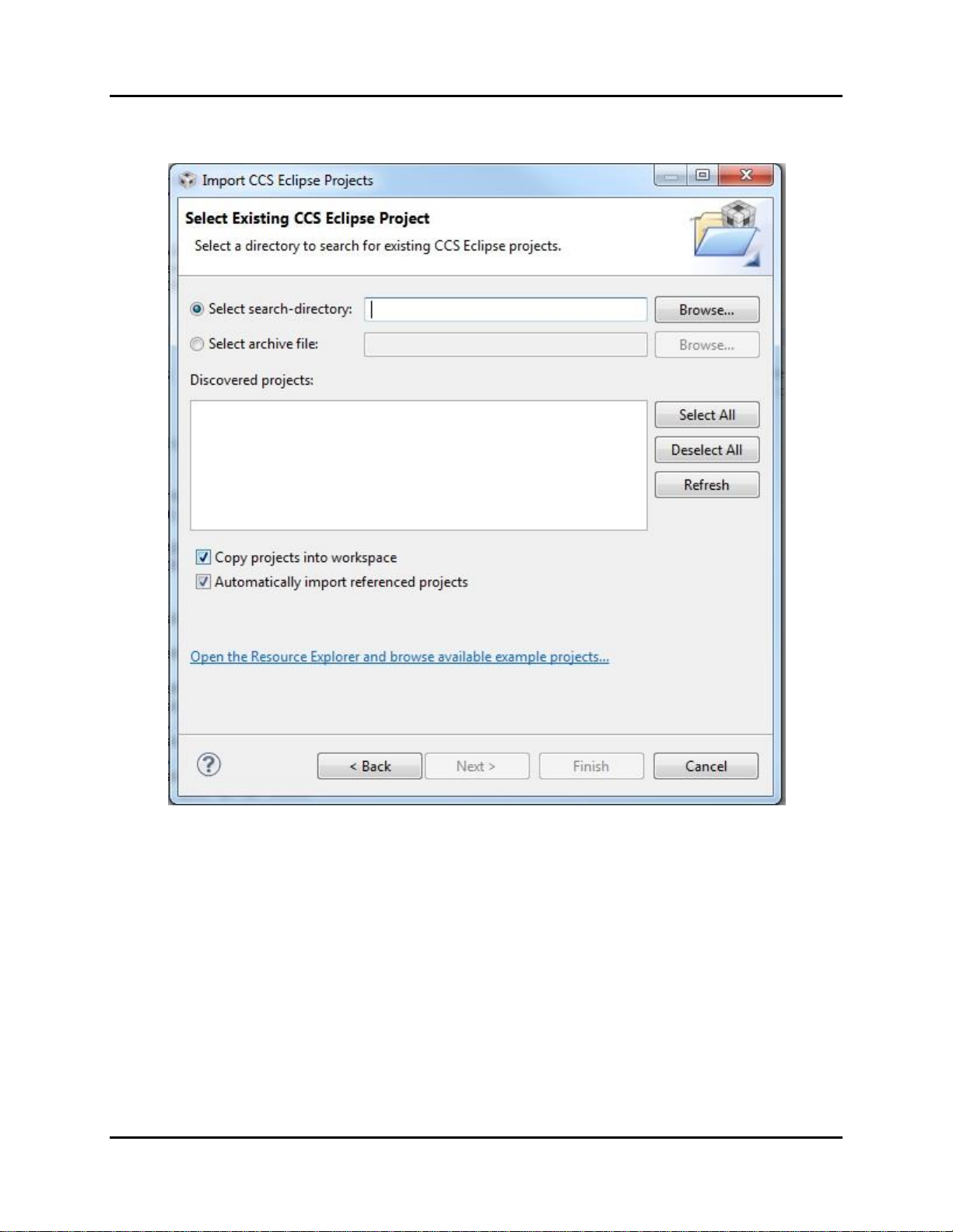
6. Select Import Project from the TI Resource Explorer or Import… > Code Composer Studio >
Existing CCS Eclipse Projects from the File Menu. The following window will appear.
7. Browse to the folder where the S5U13781R00C10M MSP430 BoosterPack Software Package
is installed.
8. The msp430_s5u13781r00c10m_demo project should now be shown in the “Discovered
Projects” list.
9. Make sure there is a check mark on “Copy projects into workspace” and “Automatically
import referenced projected”.
10. Select msp430_s5u13781r00c10m_demo and click Finish.
11. The Select msp430_s5u13781r00c10m_demo and click Finish. project should now be listed
in the CCS Project Explorer.

MSP430Ware Drivers and Demo Software
S5U13781R00C10M User Manual Seiko Epson Corporation 17
(Rev.1.2)
5.3 Software Description
The S5U13781R00C10M MSP430 BoosterPack Software Package consists of the 2 parts: driver software
and demonstration software.
5.3.1 Driver Software
Drivers are required to integrate the S1D13781R00C reference board into the MSP430 Launchpad
environment. Several drivers are required to support the S1D13781 LCDC functions, integrate the
S1D13781 into the MSP430Ware development system, and interface to the Serial Flash memory included
on the S5U13781R00C100 reference board.
S1D13781 LCDC
Driver source code is provided that supports the main features of the S1D13781. The source code is found
in the “./drivers” folder and supports features such as: (see “readme.txt” file)
•SPI Host interface (used to connect with the MSP430 MCU). This includes low level functions
such as register and memory read/write access and initialization of the S1D13781.
•Main Layer configuration
•PIP Layer configuration
•Alpha Blend, Transparency, Rotation, PIP modes, etc.
The “S1D13781.h” file defines register initialization values for the 3.5” and 4.3” LCD modules. Each
type of LCD module has a “#define xxxxx_PANEL” macro in the “Panel/System Selection” section of
“S1D13781.h”. Only one should be uncommented and the rest commented out. For example, to select
4.3” LCD module, uncomment “#define WQVGA_PANEL” and comment out “#define
QVGA_PANEL”.
The specific features supported may change without notice and may be added to as additional
functionality is required.
MSP430Ware Integration
Driver source code is provided that integrates the SD1D13781 drivers and the MSP430Ware graphics
library. The following functions, as defined in the MSP430Ware structure tDisplay, are supported:
•Draw Single Pixel
•Draw Multiple Pixels
•Draw a Horizontal Line
•Draw a Vertical Line
•Draw a Filled Rectangle
•24-bit RGB to Display Color Translation
•Flush Cached Drawing
For details on these functions, refer to the MSP430Ware graphics library (see grlib.h).

MSP430Ware Drivers and Demo Software
18 Seiko Epson Corporation S5U13781R00C10M User Manual
(Rev.1.2)
Serial Flash Memory
Driver source code is provided that supports read/write access to the 2MByte serial flash memory
included on the S5U13781R00C reference board. The driver also supports other IO functions common to
a serial flash memory device.
5.3.2 Demonstration Software
Source code for an application that demonstrates the main features of the S1D13781 LCDC is contained
in “./main.c”. The purpose of this application is twofold:
•it provides a working example of the main features of the S1D13781 LCDC
•it provides source code which the user can utilize as the starting point to programming the
S1D13781 LCDC from within the TI MSP430Ware development system
Feature Support
The demonstration application source code provides example implementation for the following
S1D13781features.
•S1D13781 initialization
•Serial flash initialization
•Drawing to the Main Layer
•Drawing to the PIP Layer (including PIP position, PIP rotation, PIP transparency, and various PIP
modes (i.e. fade, etc.))
•Alpha Blend (including various blend levels)
•Backlight control
The specific features supported may change without notice and may be added to as additional
functionality is required.
5.4 Software Modification
Once all the tools and components are setup and configured, the Code Composer Studio IDE allows
modification, building, and debugging of the source code. All source code developed for the
S5U13781R00C10M MSP430 BoosterPack Software Package is provided “as is” and may be modified
and/or re-used in developing applications for use with the S5U13781R00C10M.
5.5 Software License
For license information about the source code developed for the S5U13781R00C10M MSP430
BoosterPack Software Package, see the copyright information included in the source code.
MSP430 / Stellaris LM4F120 Launchpad Connections
S5U13781R00C10M User Manual Seiko Epson Corporation 19
(Rev.1.2)
6 MSP430 / Stellaris LM4F120 Launchpad Connections
The following tables show the signals of the MSP430 and Stellaris LM4F120 Launchpad connectors
which are used by the S5U13781R00C10M BoosterPack LCDC Development Package:
J1
MSP430 Launchpad Signal
Stellaris LM4F120
Launchpad Signal
S1D13781 LCDC
BoosterPack Usage
1
VCC (3.3V)
VCC (3.3V)
VCC (3.3V)
2
P1.0/TA0CLK/ACLK/A0/CA0
PB5/AIN1/SSI2Fss/T1CCP1/CAN0Tx
SPI1_CS#
3
P1.1/TA0.0/UCA0RXD/UCA0SOMI/A1/
CA1
PB0/U1Rx/T2CCP0
SPI2_SOMI
4
P1.2/TA0.0/UCA0TXD/UCA0SIMO/A2/
CA2
PB1/U1Tx/T2CCP1
SPI2_SIMO
5
P1.3/AD10CLK/CAOUT/VREF-/A3/CA3
PE4/AIN9/U5Rx/I2C2SCL/CAN0Rx
-
6
P1.4/SMCLK/UCB0STE/UCA0CLK/
VREF+/A4/CA4/TCK
PE5/AIN8/U5Tx/I2C2SDA/CAN0Tx
SPI2_CLK
7
P1.5/TA0.0/UCB0CLK/UCA0STE/A5/C5
/TMS
PB4/AIN10/SSI2Clk/T1CCP0/CAN0Rx
SPI1_CLK
8
P2.0/TA1.0
PA5/SSI0Tx
SPI2_SIMO
9
P2.1/TA1.1
PA6/I2C1SCL
SPI2_CS#
10
P2.2/TA1.1
PA7/I2C1SDA
-
J2
MSP430 Launchpad Signal
Stellaris LM4F120
Launchpad Signal
S1D13781 LCDC
BoosterPack Usage
1
GND
GND
GND
2
XIN/P2.6/TA0.1
PB2/I2C0SCL/T3CCP0
LED_CTRL
3
XOUT/P2.7
PE0/AIN3/U7Rx
-
4
TEST/SBWTCK
PF0/U1RTS/SSI1Rx/CAN0Rx/T0CCP0/
NMI/C0o
-
5
RST*/NMI/SBWTDIO
RESET#
-
6
P1.7/CAOUT/UCB0SIMO/UCB0SDA/A7
/CA7/TDO/TDI
PB7/SSI2Tx/T0CCP1
SPI1_SIMO
7
P1.6/UCB0SOMI/UCB0SCL/A6/CA6/
TDI/TCK
PB6/SSI2Rx/C0CCP0
SPI1_SOMI
8
P2.5/TA1.2
PA4/SSI0Rx
SPI2_SOMI
9
P2.4/TA1.2
PA3/SSI0Fss
SPI2_CS#
10
P2.3/TA1.0
PA2/SSI0Clk
SPI2_CLK
J3
Stellaris LM4F120
Launchpad Signal
S1D13781 LCDC
BoosterPack Usage
1
VBUS (5.0V)
-
2
GND
GND
3
PD0/AIN7/SSI3Clk/SSI1Clk/I2C3SCL/
WT2CCP0
MIO0*
4
PD1/AIN6/SSI3Fss/SSI1Fss/I2C3SDA/
WT2CCP1
MIO1*
5
PD2/AIN5/SSI3Rx/SSI1Rx/WT3CCP0
MIO2*
6
PD3/AIN4/SSI3Tx/SSI1Tx/WT3CCP1
MIO3*
7
PE1/AIN2/U7Tx
MIO4*
8
PE2/AIN1
-
9
PE3/AIN0
-
10
PF1/U1CTS/SSI1Tx/T0CCP1/C1o/TRD1
SPI3_SIMO

MSP430 / Stellaris LM4F120 Launchpad Connections
20 Seiko Epson Corporation S5U13781R00C10M User Manual
(Rev.1.2)
*MIOx signals are multi-function, depending what type of LCD module is connected. Demo firmware
and drivers currently do not support these signals.
J4
Stellaris LM4F120
Launchpad Signal
S1D13781 LCDC
BoosterPack Usage
1
PF2/SSI1Clk/T1CCP0/TRD0
SPI3_CLK
2
PF3 /SSI1Fss/CAN0Tx/T1CCP1/TRCLK
SPI3_CS#
3
PB3/I2C0SDA/T3CCP1
-
4
PC4/C1-/U4Rx/U1Rx/WT0CCP0/U1RTS
-
5
PC5/C1+/U4Tx/U1Tx/WT0CCP1/U1CTS
-
6
PC6/C0+/U3Rx/WT1CCP0
-
7
PC7/C0-/U3Tx/WT1CCP1
-
8
PD6/U2Rx/WT5CCP0
-
9
PD7/U2Tx/WT5CCP1/NMI
-
10
PF4/T2CCP0
-
The SPI1_* signals are the SPI interface signals for the S1D13781 LCD Controller on the
S5U13781R00C100 Main Board.
The SPI2_* signals are the SPI interface signals for the M25P16 Serial Flash (2Mbytes) on the
S5U13781R00C100 Main Board.
The LED_CTRL signal is for controlling (by pulse-width modulation) the LED backlight current (LED+,
LED- signals to the LCD module). The LED backlight driver circuit is on the S5U13781R00C100 Main
Board.
The MIO* signals are multi-function signals which can be used for resistive touch interface, SPI interface
to LCD module’s LCD driver chip, or general-purpose I/O. They are mainly intended to support
variations in pinout of various 54-pin LCD modules (see Section 7 and 8). Currently, demo firmware and
drivers do not support or make use of these signals.
The SPI3_* signals are intended to be used as the SPI interface to the LCD driver chip on some 54-pin
LCD modules (see Section 7 and 8). Currently, demo firmware and drivers do not support or make use of
these signals.
Table of contents
Other Seiko Epson Motherboard manuals


