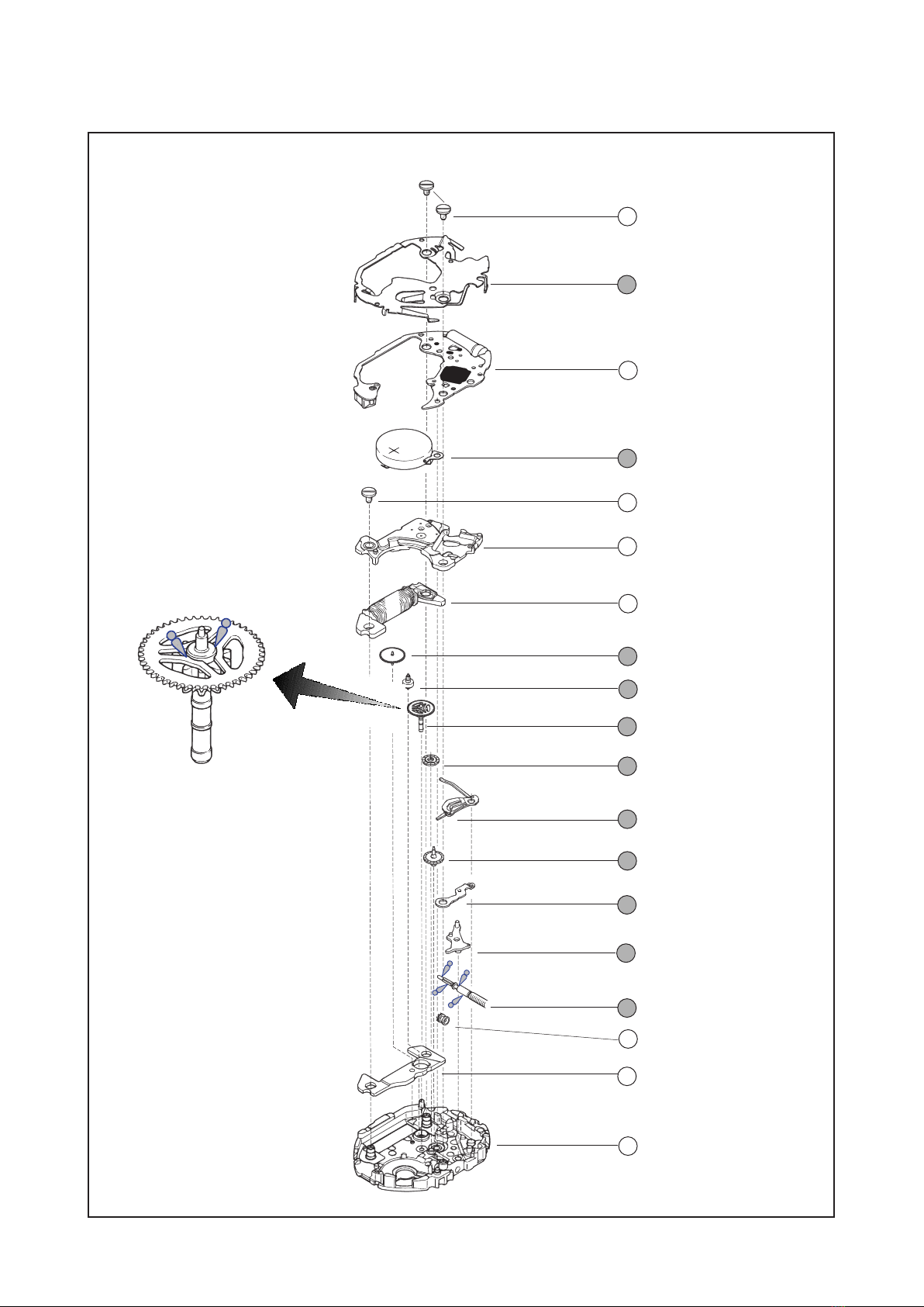
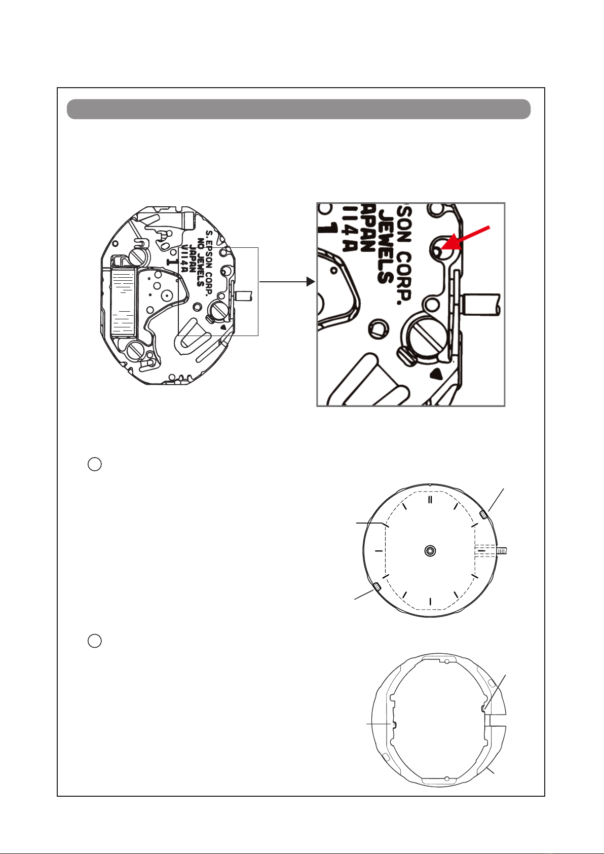
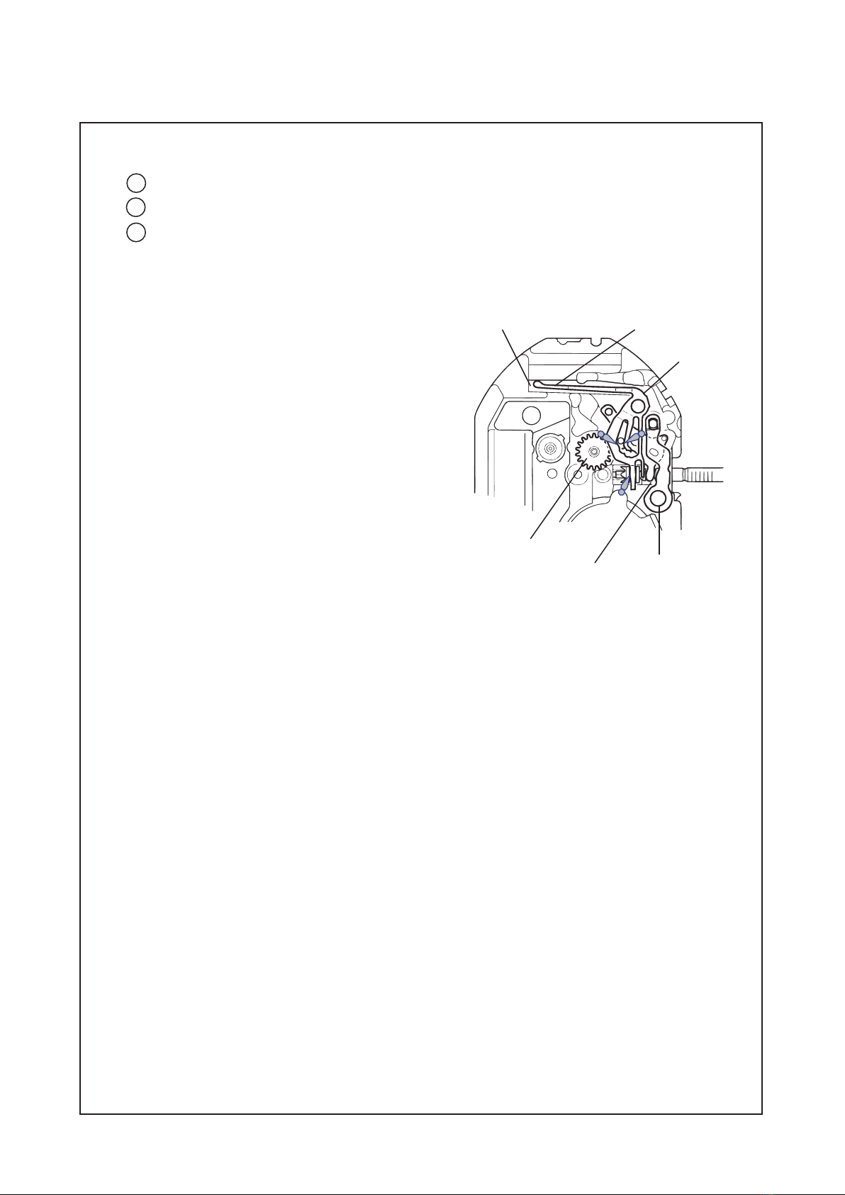
Seiko V114A Quick start guide

PARTS LIST/TECHNICALGUIDE
Analogue Solar Cal. V114A
[SPECIFICATIONS]
1/16
Item Cal. No. V114A
0 jewel
Stepping motor (Load compensated driving pulse type)
Monthly rate: Less than 15 seconds (worn on the wrist at the
temperature between -5 ºC and 35 ºC)
Use 10-second gate.
Nil
1.2 V - 2.2 V
Approx. 12 months (from full charge)
Two hands (move at 20-second intervals)
4002 909: 1.70 – 2.60 KΩ
Circuit block: Less than 0.16 μA
Movement: Less than 0.22 μA
Time setting, hand position adjustment/resetting the circuit
Free
MT516F
Solar power system
Driving system
Additional function
Crown operation
Loss/Gain
Regulation system
Gate time for rate measurement
Current consumption
Power supply
Battery life
Number of jewels
Interval of hands movements
Normal position
1st click position
Coil resistance
Power
generator
Rechargeable
battery
voltage range

SPECIFICATIONS
2/16
Cal. V114A
Cal.V114A is ladie's 2 hands analogue watch employing a new solar panel (3 cell unit), but the
basic movement structure of Cal.V114A is smilar to the previous Cal.V11 Series watches, and the
knowledge and technique you have gained in handling the previous Cal.V11 Series watches will
come in handy when you repair Cal.V114A.
FEATURES
C a l . V114 A
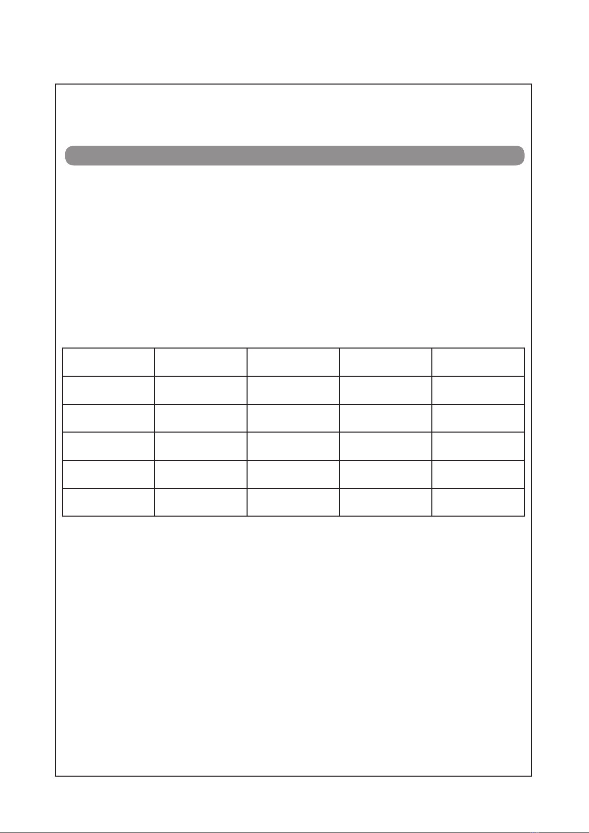
lGuideline of charging time
This is the ladies' analogue watch powered by light energy. The battery used in this watch
is a rechargeable battery, which is different from ordinary silver oxide batteries. Unlike other
disposable batteries such as dry-cell batteries or button cells, this rechargeable battery can be
used over and over again by repeating the cycles of discharging and recharging.
The capacity or recharging efficiency of the rechargeable battery may gradually deteriorate for
various reasons such as long-term use or usage conditions. Worn or contaminated mechanical
parts or degraded oils may also shorten recharging cycles. If the efficiency of the rechargeable
battery decreases, it is necessary to have the watch repaired.
Light source Illumination (lux) Time required for
full charge
Time required for
steady operation
Time to charge 1
day of power
Fluorescent light 700 - 60 hours
30W 20 cm/
Fluorescent light 3,000 10 hours 35 minutes
30W 3 cm/
Fluorescent light 10,000 60 hours 4 hours 12 minutes
Cloudy weather/
Sunlight 10,000 60 hours 4 hours 12 minutes
Fine weather/
Sunlight 100,000 10 hours 0.5 hours 2 minute
The above table provides only a general guideline.
It is recommended that the watch be charged for as long as the charging time according to the
column "Time required for steady operation" in this table in order to assure the stable movement
of the watch.
lCaution for charging
When charging the watch, do not place it too close to a photo flash light, spotlight, incandescent
light or other light sources as the watch temperature will become extremely high, causing
damage to the parts inside the watch.
When exposing the watch to sunlight to charge it, do not leave it on the dashboard of a car, etc.
for a long time, as the watch temperature becomes extremely high. While charging the watch,
make sure the watch temperature does not exceed 50 ºC.

Cal. V114A
PARTS LIST
3/16
[SOLAR POWER GENERATION MECHANISM]
0022 221
•Circuit block cover screw (2 pcs.)
•Train wheel bridge screw (1 pc.)
2 Dial
1 Hour and minute hands
3 Case ring
Movement
4025 578
Solar cell
80271 946
Hour wheel
70491 735
Dial washer
64246 644
Solar cell lead
terminal
4225 929
Solar cell holder
5
4
Reassembling procedures Figs. : 27 1
Lubricating : Types of lubricant
Lubricant quantity:
Normal quantity

Cal. V114A
PARTS LIST
4/16
[BATTERY AND ELECTRONC CIRCUIT - GEAR TRAIN MECHANISM AND STEPPING
MOTOR SETTING MECHANISM]]
Setting wheel
Yoke
Minute wheel
9 0022 221
Circuit block cover screw
10 4461 523
Circuit block cover
Clutch wheel
26 4239 909
Rotor stator
27 0100 969
Main plate
Setting lever spring
Setting lever
24 Setting stem
Center wheel and pinion
17 4146 557
Step rotor
Third wheel and pinion
15 4002 909
Coil block
Train wheel bridge
13 0022 221
Train wheel bridge screw
12 3027 26T
Rechargeable battery unit
11 4000 657
Circuit block

Cal. V114A
PARTS LIST
5/16
lHow to find the correct parts, if not determined by the 4-digit caliber number
lTools and consumables required for disassembling/reassembling
Following parts are determined based on the design of watches, such as hands height, dial
choose corresponding parts.
The type of case ring is determined based on the design of cases. Check the case number
and refer to the "Parts Catalogue web site" to choose a corresponding case ring.
The type of setting stem is determined based on the design of cases. Check the case number
and refer to the "Parts Catalogue web site" to choose a corresponding setting stem.
• Movement holder
• Watch oils

TECHNICAL GUIDE Cal. V114A
6/16
REMARKS ON DISASSEMBLING AND REASSEMBLING THE MOVEMENT
lHow to remove the SETTING STEM before dismantling the movement
lSolar power generation mechanism - positions of the hooks
Dial
Guide protrusion ”B”
of the case ring
Guide protrusion
“A” of the case ring
“b” portion
“a” portion
Case ring
Fig. 1
• How to install
Set the notched portions of the dial to
the guide protrusions "A" and "B" of
the case ring, and check that the dial is
fixed in position.
Note: When checking the assembling
of the hands, hold the dial securely as it
easily comes out of position.
• How to install
The case ring has two protrusions at
the "a" and "b" portions as shown int
the ilustration at right, and it is fixed to
the movement by the protrusions.
To install the case ring, push it above
the "a" and "b" portions so that the
protrusions catch the movement
securely.
Crown position: Normal position

TECHNICAL GUIDE Cal. V114A
7/16
Solar cell holder Solar cell
• How to remove
Release the four hooking portions marked
with the arrows in the illustration at right
from the main plate, using tweezers or the
like.
• How to install
Push the solar cell above the four hooking
portions marked with the arrows in the
illustration at right so that they catch the
main plate securely.
Notes:
* When removing or installing the solar cell holder, take care not to damage the solar cell.
* If the solar cell is damaged, its power generating capacity may be greatly decreased. In that case, check
the output voltage for the solar cell unit, following the procedure in the corresponding section of this
guide. If the voltage is not normal, replace the solar cell unit with a new one.
* If the solar cell is soiled, gently wipe it with a soft chamois or the like soaked with alcohol, taking care
not to damage it.

TECHNICAL GUIDE Cal. V114A
lRechargeable battery and electronic circuit
12
• How to install
Set the “B” portion of the (-) lead terminal
of the rechargeable battery unit to the
groove of the main plate, and then, set the
“A” portion of the (-) lead terminal to the
guide post of the main plate.
Notes:
so as not to short-circuit its (+) and (-) terminals.
be deteriorated.
* Never wash the rechargeable battery unit as
it is an electronic part.
Rechargeable battery unit
Guide
post
“A” portion of
the (-) lead terminal
“B” portion of
the (-) lead terminal
• How to remove
Remove the two circuit block cover screws,
and then, release the two hooking portions
marked with the arrows in the illustration at
right from the main plate.
• How to install
Set the circuit block cover so that the two
hooking portions marked with the arrows in
the illustration at right catch the main plate
securely, and then, tighten the circuit block
cover screws.

TECHNICAL GUIDE Cal. V114A
9/16
lGear train mechanism - Wheel assmbly position and lubrication instructions
• Setting position and lubricating
Refer to the illustrations below for the setting position and lubrication of the
respective wheels.
Lubriccating: Types of lubricant
Lubricang quantity:
Normal quantity
Step rotor Minute wheel
Setting wheel
Center wheel and pinion
Third wheel and pinion
Third wheel
and pinion
Step rotor
Center wheel
and pinion
Setting wheel
Minute wheel
qj
qh
qk
ql
wa
qj
qh
qk
wa
ql

TECHNICAL GUIDE Cal. V114A
10/16
lSetting mechanism - Assembly position and lubrication instructions
• Setting position and lubricating
Refer to the illustration below for the setting position and lubrication of the respective parts.
catch the protruded portion of the main plate
("A" portion in the illustration).
Note: Take care not to install the setting lever
spring upside down. (Refer to the
illustration at right.)
“A” portion
Setting lever spring
Spring portion of the yoke
Setting lever
Minute wheel
Yoke
wd
w;
ws

TECHNICAL GUIDE Cal. V114A
11/16
REMARKS ON INSPECTION AND MEASUREMENT
lCurrent consumption
For the whole movement : Less than 0.22 μA (with voltage supplied from a battery)
For the circuit block alone : Less than 0.16 μA (with voltage supplied from a battery)
1. Remove the solar cell holder and solar cell.
2. Remove the rechargeable battery unit, and then, reassemble the circuit block, circuit block cover
and two circuit block cover screws.
(As a result, only the rechargeable battery is removed from the movement.)
3. Apply the probes of the tester as shown in the illustration below.
Note: When applying the minus probe of the tester, take care not to short-circuit the minus probe
and circuit block cover.
4. After checking that a stable measurement is obtained with the tester connected, read the current
consumption. (As the hands move at 20-second intervals, 3 to 5 minutes may be required before a
stable measurement is obtained.)
lValue checking - coil resistance (coil blocks)
lHow to measure the current consumption for the whole movement
Note: If the measurement value remains high
or unstable, shut out the light from the
movement, and make a measurement
again.
5. Wait until a stable measurement becomes available.
It usually takes 30 seconds to a few minutes for
getting a stable measurement.
μA.
* When measuring the current comsumption using
of 40 μ
Ω- 2.60KΩ

TECHNICAL GUIDE Cal. V114A
12/16
lHow to measure the current consumption for the circuit block alone
1. Apply the probes of the tester as shown in the illustration.
2. Shut out the light from the circuit block.
Note: If the circuit block is exposed to light, an extremely high measurement value may be
obtained.
3. After checking that a stable measurement is obtained with the tester connected, read the current
consumption.
lStructure of the circuit block
Coil output terminal
Crystal unit
Input terminal (+)
Input terminal (-)
C-MOS-IC
* When measuring the current consumption us-
the range of 40 μA of SUPPLY V (=1.55V) &
light in order to obtain the correct measure-
ment.

TECHNICAL GUIDE Cal. V114A
13/16
lOutput voltage for the solar cell unit
1. Connect the tester to the output terminal of the solar cell
unit as shown in the illustration at right.
Checking procedure
lChecking the recharging function
A conventional method of checking the recharging function is to check the difference of the rechargeable
battery voltage between before and after a recharge.
1. Apply the probes of the tester as shown in the illustration
at right to measure the voltage of the rechargeable battery
before recharge (initial voltage).
2. Place the watch at a distance of 5 cm under a fluorescent
light of 15 to 20 watts, and charge it for 30 minutes.
Notes:
* Use a fluorescent light to charge the watch, as light
sources generating heat may cause damage to the
watch. To charge the watch efficiently, place it under
the center of the fluorescent tube.
* While charging the watch, make sure that the watch
temperature does not exceed 60 ºC.
2. With the probes of the tester applied, place the solar cell
unit at a distance of 5 cm under a fluorescent light of 15
to 20 watts, exposing the solar cell side to the light, and
then measure the output voltage.
Checking procedure
5 cm
+
+
5 cm

TECHNICAL GUIDE Cal. V114A
14/16
3. After recharging for 30 minutes, apply the probes of
the tester in the same manner as in step "1" above, and
measure the rechargeable battery voltage while keeping
the watch exposed to the light.
4. Refer to the table below to determine whether the recharging function is normal or not.
[ Initial voltage and guidelines of normal/defective decision ]
Initial voltage Guidelines of normal/defective decision
0.5 V - 1.00 V The battery is normal if the rechargeable battery voltage obtained
after recharge is more than 1.2 V.
1.01 V - 1.2 V The battery is normal if the rechargeable battery voltage has in-
creased more than 0.08 V after recharge.
5 cm

TECHNICAL GUIDE Cal. V114A
15/16
l
Checking the general function
Function Checkpoint
Pull out the crown
to the 1st click
and push it back
in to the normal
position. Repeat
the same several
times.
Setting mechanism -
function of the time
setting
Make sure that it has
a click at the 1st click
position and the stem
is not pulled off.
Pull out the crown
to the 1st click,
then turn it.
Setting mechanism -
hour and minute
hand setting Make sure that the
hour and minute
hands move
smoothly (without
touching each other
or touching the
surface of the dial or
inside of the glass).

TECHNICAL GUIDE Cal. V114A
16/16
l
Checking the water resistance
Check the water resistance according to the designated specification of the watch.
Marking on the case back Test method Applied pressure
3 BAR
5 BAR
10 BAR
15 BAR
20 BAR
25 BAR = 200 (m) times 0.125
37.5 BAR = 300 (m) times 0.125
75 BAR = 600 (m) times 0.125
125 BAR = 1000 (m) times 0.125
Water pressure test
Condensation test
Condensation test
Condensation test
Water pressure test
Air leak test
l
Accuracy test
Measure the rate and make sure the value shows within ±0.50 s/d.
Use 10 seconds gate of the tester.
Copyright©2010 by
Table of contents
Other Seiko Watch manuals

Seiko
Seiko 7A38 User manual

Seiko
Seiko S830 User manual

Seiko
Seiko King Seiko SPB365J User manual

Seiko
Seiko 5T82 User manual

Seiko
Seiko SSJ015J User manual

Seiko
Seiko Cal. 4R15 User manual

Seiko
Seiko Arctura SKA201 User manual

Seiko
Seiko N855 User manual

Seiko
Seiko Conceptual SWR073P User manual

Seiko
Seiko Cal. 8L35 User manual

Seiko
Seiko 5R86 User manual

Seiko
Seiko KINETIC 7D46 User manual

Seiko
Seiko 7T04 User manual

Seiko
Seiko 7K52A Installer manual

Seiko
Seiko Cal. 5M82 User manual

Seiko
Seiko H-1 User manual

Seiko
Seiko V657 User manual

Seiko
Seiko G300 User manual

Seiko
Seiko 7T32B User manual

Seiko
Seiko Conceptual SUR517P User manual