Seiwa S 101E User manual

ABN 84 300 102 464
AIR COMPRESSOR HIRE
Airless Sprayer Hire, Sales & Service
Te/ephone (02) 9649 4590
Fax (02) 9646 5226
Emai/ aircorn@ozemail.comau
Dia hra m Airless S ra Units
Make Seiwa
Model S 60ElK 101(31S 101E
Serial Number ...............
PurchaseDate ...............
Warranty Period ...............
Extended Warranty ...............
Instruction Manual
Please read this manual carefully before using the equipment. Incorrect use
may lead to mechanical breakdown accident or injury. Keep this manual
r_ handy as an on-going reference.
Technical Assistance
Phone (02) 9649 4590

Introduction
Thank you for choosing our Supaspray Airless spray unitSeries 60E.
When using this equipment we trust that you will read this Instruction
Manual and gain many years of use. Please note however that for reasons of
quality,performance and other circumstances there may be variations in
component parts which will be reflected in the content of this Manual.
Should any section be unclear or if you have anyrequests,do not hesitate to
contact the nearest sales office of this company.
Table of contents Page
1. Warnings for safe usage .................................. 1
3. Part names,functions and basic operation ................ 3
4. Operationalprocedures ................................... 4
4.1 Preparation ........................... q
4.2 Confirming operation .................. 5
4.3 Commencing operation ................. 6
4.4Interrupting work,stopping work ...... 7
4.5 Shutdown and maintenance procedures .. 8
4.6 Airless gun operation ................. 10
4.7 Clamp knob usage ...................... 10
4.8 Nozzle tip diameter and gun filter...... II
5.Maintenance and inspection ............................... 12
5.1 Changing oil .......................... 12
5.2Changing diaphragm ................... 12
5.3 Changing outlet valve ................. 13
5.4 Changing suction valve ................ 13
6.Trouble-shooting ............................................... 14
7. Parts list ...................................................... : 15
J

1. Warnings for safe usage :
,)
Before using the equipment please make surethat you have read and understood the
Instruction Manual and observe all warnings when operating.
High presssure caution!
Airless painting equipment generatesextremely high pressure. Paint sprayed under
high pressure can cause personal injury so please observe the following precautions.
• Never pull trigger on airless gun when aimed " Do not use equipment if safety lock will not
at a person. For safety, when not in use or engage, or if trigger will not return or if
whenremoving nozzle tip, always engage there is a leak front any connectors. Do not
safetylock. ' modifyairlessgunorremovesaI)ty
mechanisms (safety lock, safety card).
Neverplacefingersorhandsonsprayoutlet
or hring face close to it. Such actions are.
very dangerous and could lead to it\iury.
... " Do not pull or twist paint hose excessively. ° Ensure connectors are tightenened firmly to
Externally cracked,twisted or flattened paint avoid leaking. Should leaking occur, stop
hoses are more likely to break and spray the equipment immediately purge air lines
out paint. Do not.use in such condition, and lower paint pressure.
Ensure safe
..r-.)O. _ joint attachment
Alv,,ays lock when you stop work
Never increase paint pressure beyond what is required
Medical Treatment
•--Regardless-of-the-(tiquid)-paint-type,shou d yot -sustain-any sk ndamage do-not--
treat it as a minor i:njtiry but seek immediate, appropriate treatment from a medical
practitioner. Also, inform the doctor of the nature of the liquid.
OPM 101/98
1
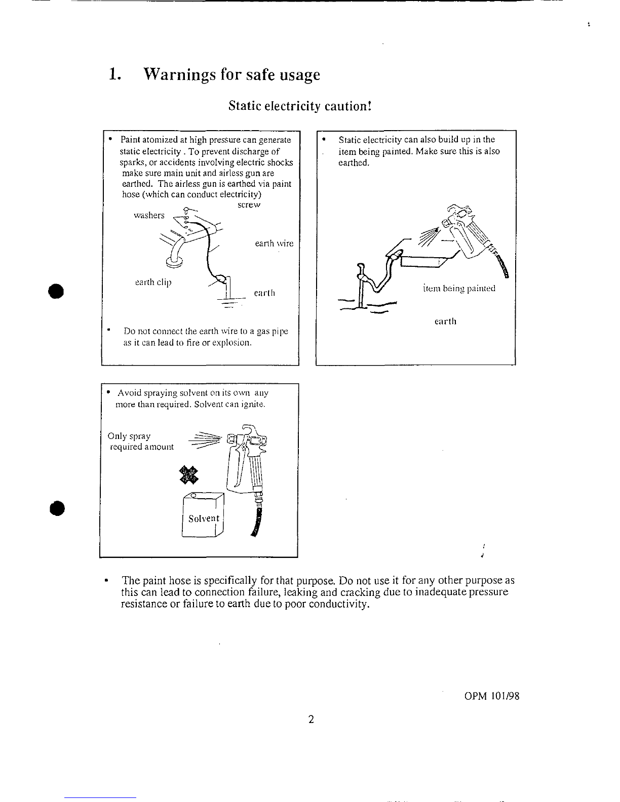
1. Warnings for safe usage
Static electricity caution!
• Paint atomized at high pressure can generate • Static electricity can also build up in the
static electricity. To prevent discharge of item being painted. Make sure tb.is is also
sparks, or accidents involving electric shocks earthed.
make sure maii_,unit and airless gun are
earthed. The airless gun is earthed via paint
hose (which can conduct electricity)
screw
washers_ _)
_" e_nhwire
earth cli
earth i em ["1_. l)ahlted
earth
Do not connect the earth wire to a gas pil_
as itcan lead to fire or explosion.
! • Avoid spraying solvent oil its o\vn any
more than required. Solvent can ignite.
Only spray _ 7_/_
required amount
d
The paint hose is specifically for that purpose. Do not use it for any other purpose as
this can lead to connection failure, leaking and cracking due to inadequate pressure
resistance or failure to earth due to poor conductivity.
OPM 101/98
2

3. Part names, functions & basic operation
(continued)
Warning!
The airless gun sprays at extremely high pressure and is dangerous. Never touch tip
of gun (spray oritice) or place it near the face.
Very high pressure is applied to paint hose. Do not twist, bend, flatten or cut with
any sharp object. This could lead to cracking and spray leakage.
When using this equipment ahvays earth it.
Failure to do so can lead to fire, explosion or electric shock.
Do not operate with the belt cover removed and do not poke sticks into the moving
parts. Clothing or bands may be dragged in.
FAILURE TO OBSERVE THESE WARNINGS CAN RESULT IN
SERIOUS INJURY
Caution!
Do not jolt or drop pressure gauge. The indicator may malfunction and cause a
breakdown.
Do not use relief valve to regulate pressure. This will shorten life of relief valve.
Do no over-rotate pressure control valve beyond its maximum. This can lead.,to
breakdowndueto excessivelyhighpressure.
3
OPM 101198

4. Operational procedures
4.1 Preparation
I. Make sure that paint hose, return hose,
airless gun and nozzle tip are all
properly connected. Do not connect Oil gauge
suction hose yet. _ /"-_-'N, oil gauge
any oil,
_ _fnormal oil levek
4. If V-belt is slack, adjust to an (_ _,_
appropriate tension.
(Oil the Super KI01G) place your
lingeronthemiddleofthebelt
andpressfirnfly.Adjustuntilslackis _ o _ 6 lira
about 5-6ram. However,
ne_er do this while in operation.
tl OPM 101198

4. Operational procedures
4.2 Confirming operation
1. Turn the relief valve right around to
"open"
2. Turnto"low"thepressure control valve around __
3. Check that suction filter is not blocked. [_ ,____ _ ). StlCtlotllf]lter.
4. After engine starts (see Engine Start
Up) turn file pressure control valve
slowly to "high"
5. Place the pahn of your haml against air
intakeand checktbrsnclion, m _ Checking suction
If there is no suction'?_/
Prime by flushing solvent "71 ]c
through suction valve.
Ifsuctionvalveisseized
press suction valve rod Suct'-'_Orl
and release.
If there is still no sound indicating
operation? --_ _ _:
Occasionallyanair-lockoccursinthe _/
hydraulicsystem. If this happens,turn _ I
pressure control valve back to "low"
and after OlX_ratingfor 1-2 minutes, /
Whenyoudothisthesolvent
used as a primer can spurt out.
Cover opening with a cloth to
protect face and clothing.
5 OPM i01/98

4. Operational procedures
4.3 Commencing operation
operating, return t pressure control valve to
"low" and connect suction hose. Suction hose
andreturnhoseare insertedintothepaint that ....
has been prepared in advance.
Caution. _ slowlv turn to "low"
Donotusepaintssuchas lysineetc _ -"
that contain aggregate.
Take note of the allowable operating
time for two-part paints. Make sure
you stop within recommended time an
clean up thoroughly.
When stirring paint take care not to
aerate it. Aeration can cause suction
failure.
2. Check that relief valve is set at "open". Slowly
turn pressure c°ntr°l valve t° "high" and l?aint _ fill)
will start to come out of return hose. "
3. Remm pressure control valve a half-revolution
4. Turn relief valve to "close".
5. Slowly turn pressure control valve to "high"
while pulling the trigger of the airless gun and "'-"""
paint willcome out of the nozzle. Then release
gun trigger and re-set pump to desired spraying I_ {_
6. Adjustpressure control valve to pressure that is _-'- '"
appropriate for the paint then start work. _ D_: _,';/J _, low I'agh
/"-0_ relief xalvc
• v _Q.-'_"j
Caution.
._Turn to Half-turn to
When ilot working or when changing ,,b,,_wJ "close.... low"¢
nozzle always activate safety lock 011 _ #
airless gun to prevent mishap.
Ensureadequate ventilation while ti}
working and work in a location where _ f'"_---"'_
there is good air movement. Wearing a
face mask against dust is recommended
Do not forcefully turn pressure control
valve beyond maximfim setting.
Overloading, can cause breakdown.
6 OPM 101/98

4. Operational procedures
4.4 Interrupting work, stopping work
1. Turnpressurecontrolvalveto"low"
2, Turnreliefvalveknobto"open"
3. Run tbr 1-2 minutes withthrottle lever in the t'_c-M,,,_ ' °Pen close pressure
"low speed" positioi_. _.mlicf" valve '
5. Close fuel cock. _,/"_"_'_--..__ _""_-ff /_
7
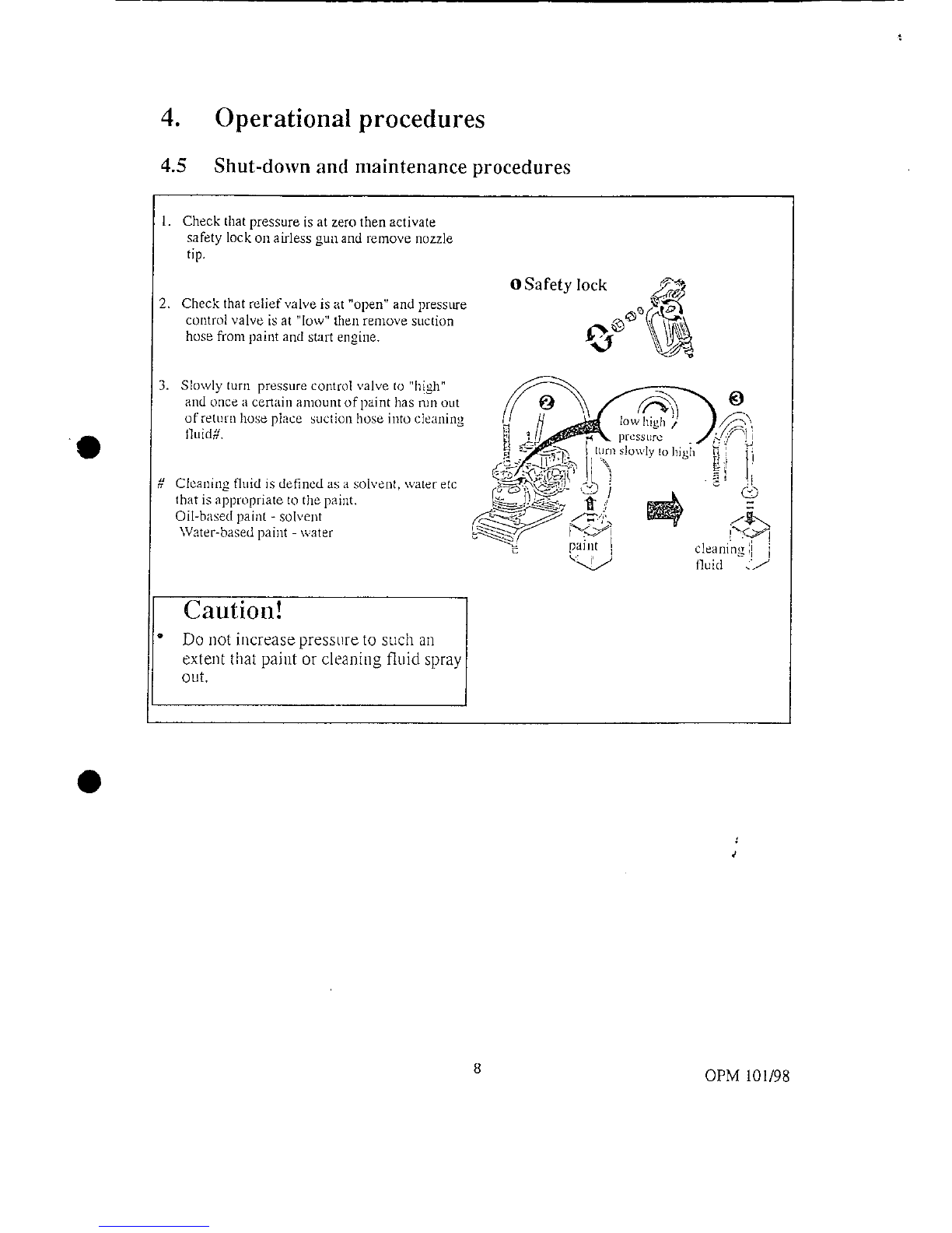
4. Operational procedures
4.5 Shut-down and maintenance procedures
l. Check that pressure is at zero then activate
safety lock on airless gun and remove nozzle
tip.
OSafety lock _,,-_._
2. Check that tel ef valve s open and press _re
control valve is at "low" then remove suction ..,,,_@ _{._('_\
hose from paint and start engine.
",0
3" Sl°wlyturn pressurec°ntr°lvalvet°"high" .___\
and once a certaiii amount of paint has i_lnout
ofreturnhoseplacesuctionhoseintocIeaning ,,
._? ' It: .:, _
# Cleai:ing fluid is defined as a solvent, water e_c r-_-_-_-_-_-_-_-_-_-,A_DY-:x_:,, ,_ ]" _, _ (28:x
that is appropriate to the paint, g_ .,._.: _" q _ _
OiI-baset.I paint- solvent _ _'../__._:, I_ Zg"-..
Water-based paint- water _ _ paint I cleaning',l i
"_ fluid Z'.J
Caution!
° Do " I _
not increase presst re to such an
extent that paint or cleaning fluid spray
out,
8 OPM 101/98

4. Operational procedures
4.5 Shut-down and maintenance procedures (continued)
4. Once cleaning fluid has run outof return hose,
turn relief valve to clo.e , disengage safety
lock oi1airless gun, pull trigger and purge paint __._..__
outofhose. _
recycle fluid in that state for ashort time in (_
order to clean out the l)aint system. _ " -- . "'
6. Remove suction hose from cleaning fluid'and
purge cleaning lluid in paint hose from airless
_tl[1,
va]vo tO "opell", [)Ul'ge c]eafling e/_:, e
7.
"I'Ll r ]l
relief
fl ( lrettrnh)suandfinishbyturnin,.z,.@ .!, ;q;I _t
Ca:=a,
pressure control valve to "low". _ ] • .- _l J
8. Ren'_ove suctiort filter, _un filter and nozzleand_ _ ._fl":'J"-/'_' ../"=....'_"_
clear away any build-up of matter or paint, cleamng ,]j i._.._,_p
fluid ._,l.,..J cleaning l I
"v tTuid
Caution! @
When not in LlSe for an extended perio __---"L,_ _"_
totally purge cleaning fluid ai]d fill _ _. li_!--! !1_ l_._ L_.__.]
suction valve with rust -proofing oil to open close lowhigh
prevent seizing, reliefvalvc pressure
Never discharge paint waste or waste _ _ "
cleaning fluid into natural water
systems, sewers etc. Request removal
by an industrial waste collector.
9 OPM 101/98

4. Operational procedures
4.6 Airless gun operation
1. 2.
use accessory tool ,,,_
__ _.___@ .... @4. or with
manua,ly ac es o,:eool
Remove nozzle _ipor gun filter as illustrated. If nozzle tip is
blocked, remove tip and clear blockage by b[o',ving in air flora
opposite direction. When attaching, check that gasket is in place
and tighten firmly.
ailn gl.nlat surface tbr paintiiag Caution !
and move horizontally keeping a
steady speed and maintaining an " Under no circuinstai_ces change the nozzle tip or
intep,'al ofapproximately 30crn. remove the filter when tile pressure is oi1. Paint
spraying out is dangerous.
4.7 Clamp knob usage
Spray lock Safety lock
(continuous spray) Caution!
• For safety reasons,
Clampknob Clampknob when not paillting or
_ removed,always
---- engagesafetylock.
• Paint build-up c)n
cause a breakdown.
trigger trigger Make sure cleaning
and lubrication is
Pull trigger back, then release Without pulling trigger carried out.
it while turning knob so that turn knob so that it faces
arrow on knob points to gun side of handle.
tip. If you pull it again it will
automaticaiIy disengage.
10 OPM 101198

4. Operational procedures
4.8 Nozzle tip diameter
_/_rlLshes Lioht Body 100-150 .009..011
Laceuer Finishe,_JClear) - - .009, ,0! 1
__a_ndingSealers - - .009,.011
ShellacIClear) - - .009,,013
TransparentStain - .011.013
WaterSealers(Clear) - - .011.013
SolidStains MediumBody 60-100 .013 .015
ExteriorHousePaints - .013.015
InteriorWallPaints - .015.017
Interior & Exterior Primers - .017 .019
Commercial Grade Architectural Heavy Body 30-60
Coatinqs- - -
InteriorWallPaints - .017.010
InteriorWallPrimers - .017 .019
DryFail(QuickDry] - .019.023
One Coat, Primers-Finish Paints - - .019 .023
Elastomerics ExtraHeavy - .021 .031
P_LgmentedWaterproofers - - .021 .027
Block Filler- .025.031
The on'rice size recommended on this chart are based on fan widths between 8 and 12 inches.
Caution!
After using, always wash in readiness for the next usage. Remove gtln filtei inside
handle and clean with a brush.
11 OPM 101/98

5. Maintenance and inspection
5.1 Changing oil
1. 2.
o o
_./_ appropriate
qJ.y
=
Drain plug
CoMirm that drain plug is ill place then pour in approx. 900cc of
Remove oil cap and drain plug to oil and check using oil gauge. Overfilling will result in Ieaking
'0 drain oil. via reliefvalveduringoperation.
Caution!
Please take waste oil to your nearest petrol station. Never dispose of ill natural water
courses or sewers.
Please use "High Power Oil". Do not use any oiI other than our proprietary oil.
Abnormally high tetnperatures and loss of perforinance can lead to breakdowns and
shorten the life of the product.
5,2 Changing diaphragm
1. ,paintcover 2. _
holed painthousing_/ j
hex bolt
diaphragm set
Remove paintcover.
Remove the 6 holed hex bolts Change diaphragm for each set and assemble. When tightening
using the corresponding 8ram the 6 holed hex bolts,tighten uniformly in sequentially diagonal
hexkey. order.
12 OPM 101/98

5. Maintenance and inspection
5.3 Changing outlet valve 5.4 Changing suction
valve
Should paint particles or aggregate enter As with the outlet valve
the vatve it willshow markedwear. certain paint will also cause
marked wear. Please change
using the suction valve set.
l. 2. 1.
27mm hex
spanaer _.._d" key
Remove discharge Remove outlet valve holder Confirm that gasket is firmly
valve using using corresponding 12nml in place.
corresponding 27ram hex key.
spanner.
13 OPM 101/98

6.Troubleshooting
6.2 Pump system
Problem Cause Action
air purging has not been • purge air
No suction strength carriedout
sticking of suction/ • carry out primingand
discharge valves clear any adhesion by
inserting a rod into the
suction valve
pressure control valve turi] pressure control
has loosened toward the valve slightly towards
"low"setting "high"
air build-up in hyraulics purge using instructions
on paget0
insufficient oil volume fill up to recommended
level
suction filter blocked clean or replace
Has suction but no uptake incorrect suction hose _• tighten firmly
attachment has drawn in
air
suction hose is not immerse in the paint
immersed in paint
paint viscosity too high reduce viscosity
Paint will not spray from ! • suction filter or paint clean oi7replace
gun passage blocked clean or replace
paint blocking nozzle tip
Pressure low relief valve not tightened •tighten fui_her
properly
pressure controI valve turF_pressure control
adjustment incorrect valve to ':high"
Pressure variation failure of suction or replace
outlet valves
damaged diaphragm replace
worn piston, cylinder replace
contaminantsin replace
hydraulic systein disassemble and clean
suction hose failure replace
air enteringviasuction tighten ,
valve J
insufficient oil volume fill up to recoi-nmended
level
contaminants in paint remove contaminants
system
Oil on sprayed paint diaphragmcracked clean and replace
surface diaphragmandoil
Oil contaminated by pMnt
14 OPM i01/98

OPERATING PROCEDURE FOR S60GE
PREPARATION
I. Connect paint hose, suction hose, return hose and airless gun
properly.
2. Check the oil levels.
3. Check that the unit is switched 'off' connect to 2LIOV power. Do not
exceed 15 metres if using extension cord.
WARNING: All power supplies and cords must be earthed.
START
1. Turn pressure regulating and relief v:,l',,'es al:ti-clockwise to their limit.
2.Insert suction and return hoses into material to be sprayed.
3. Switch on motor and turn pressure regulating knob slowly clockwise.
4. When material is being returned to the can via the return hose (when
bubbles stop appearin 9 in the can) the pump is primed.
5. Turn the relief valve clockwise slowly to it's limit. Wait for the hose to
_Lfill with material and tile pressure gauge indicates approximately 3000
psi and adust pressure to suit material.
Youare now ready tospray,
SAFETY INSTRUCTIONS
HIGH PRESSURE
I. Never pull the triggerof the gun toward people. Unlock the trigger
ONLY when you spray tile paint or take off the nozzle tip.
2. Never use a damaged hose. Due to the high pressure even a small flaw
may cause an accident.
3. Pressure is very high and extremely dangerous. You must handle it
with meticulous care.
4. Do not raise the pressure unnecessarily.
5.Connect all the attachments properly and tightly sothat no paint will
leak. If paint leaks while you are working, stop the pump immediately.
Le t--t he-a ir_goind_low e r--t-h e-pre s s u r e., --
6. Ensure you are using the correct hose. Contact PhillroIndustries on
03 9369 4000 or freecall 1800 816 200 if in doubt.

Phillro Industries
ABN 17 529 873 703
28 Home Street
Hoppers Crossing 3029
Phillro
Werribee, Vic. 3030
Phone: (03) 9369 4000
INDUSTRIES
TROUBLE SHOOTING
General Surfaces Tip Recommendations Chart
Fanwidth (In.)
Surfaces Materials Filter at 12In.Orifice
Mesh 6-8 8-10 10-12 12-14Size(in.)
Wood Interior Stain,Sanding Sealer 100 • • .011
Cabinets,Paneling Lacquer, Varnish • • .013
Shellac
terior Walls or Ceilings Latex,Vinyl,Acrylic 60 ••• .015
Drywall, Plaster • • •.017
•••,019
Overhang Primers, Enamels 60 • • @ .015
•@.017
•.019
Masonry Vinyl, Acrylic, Latex, 60 • • .017
Block, Stucco, Oil Base, Alkyds •.019
Concrete @ • .021
Wood Exterior Exterior Stains, Latex, 60 •.017
Shingle, Siding, Vinyl,Acrylic O .019
Shiplap • O .021
Open Joist and Ceiiing Mill White,Hi Builds 60 •,019
Areas • .021
I • .023
i SPRAY WIDTH PATTERN
12in 11 in 9in S5in
(305ram) (280mm) (229mm) (140turn)
New worn to worn to worn to
15Tip 017 .019 021
FLOW RATE
/,gpm V_gpm 3/8gpm '12gpm
(.87 Ipm) (1.14 Ipm) (1.4 fpm) (1.74 Ipm)
J
Gen alEquipment In ' ' ::
_er s)ectlon ,,.
Symptom Whatto Check What to Do
Sprayer will not Air in paint pump Open prime valve to purge air
1. Filters (clean and proper sizing) prime/takes too from paint pump
• Inlet screen tongto prime. Inletstrainerclogged Cleanstrainer
• Gun filter Note:Causedby
insufficientcleaning Siphon/immersion tube loose Tighten fittings
2 Siphon and Immersion Feed and/ornotleavingpaint
•Loosehose connections thinnerinunlt
• Loose elbow fittings • Sprayer loses its Siphon/immersion tube loose Tighten fittings
• Hose kinks, cracks, holes and material build up pdme while
3 Paint Hoses spraying Worn suction valve or . Service/replacesuction valve
•Kinks in hose outlet Valvecomponents • Service/replaceoutlet valve
• Blisters in hose coverSprayer doesn't Spraytipworn out Replacespray tip
• Abrasions,exterior damage to hose cover have enough Filters clogged Clean filters
4.Gun Tip pressure at thegun Filtration beingused for Operate without filter
• Clean and working safely or pressure drops the wrong coatings (i.e.or change coating
• New tipoff.blockfilters,elastomerics)
• Tip guard in place,good condition.Usingwrong sizefilter meshCoarserfilter mesh:30is60;
60 is 100
Hosetoo long and/or wrong Checksprayermanual
sizediameterfor correctsizehose.

6OE SEIWA ELECTRIC SPRAYER
3
_4
6 -2
16_.Q
17_'_ 21
18_ _22
27--._ _'_-_l_il,_._r._
_'i'--_lil"_ 23 /"_33"_. 30 (_
\
43 @ _o_ /,,o
47 _ /767_ 64
"" 48 _' t]/6869 ./
- -- _ . / / ///-76//
5_- ---_ .,_..,J// /
- 8./77 _ p-,,//
59 _ _'J.i78 96 _ .'/\'
60- -- --_ lt---79 _..'_ _4_,_""_
k / ... \\/fk-_\ _o_,o_
848__,,_./J _'oo1°'
l I--.-Z_ ./ °°
Table of contents


