Sekey Home 339833 User manual
Instruction manual
SIDE TABLE
339833
1 2
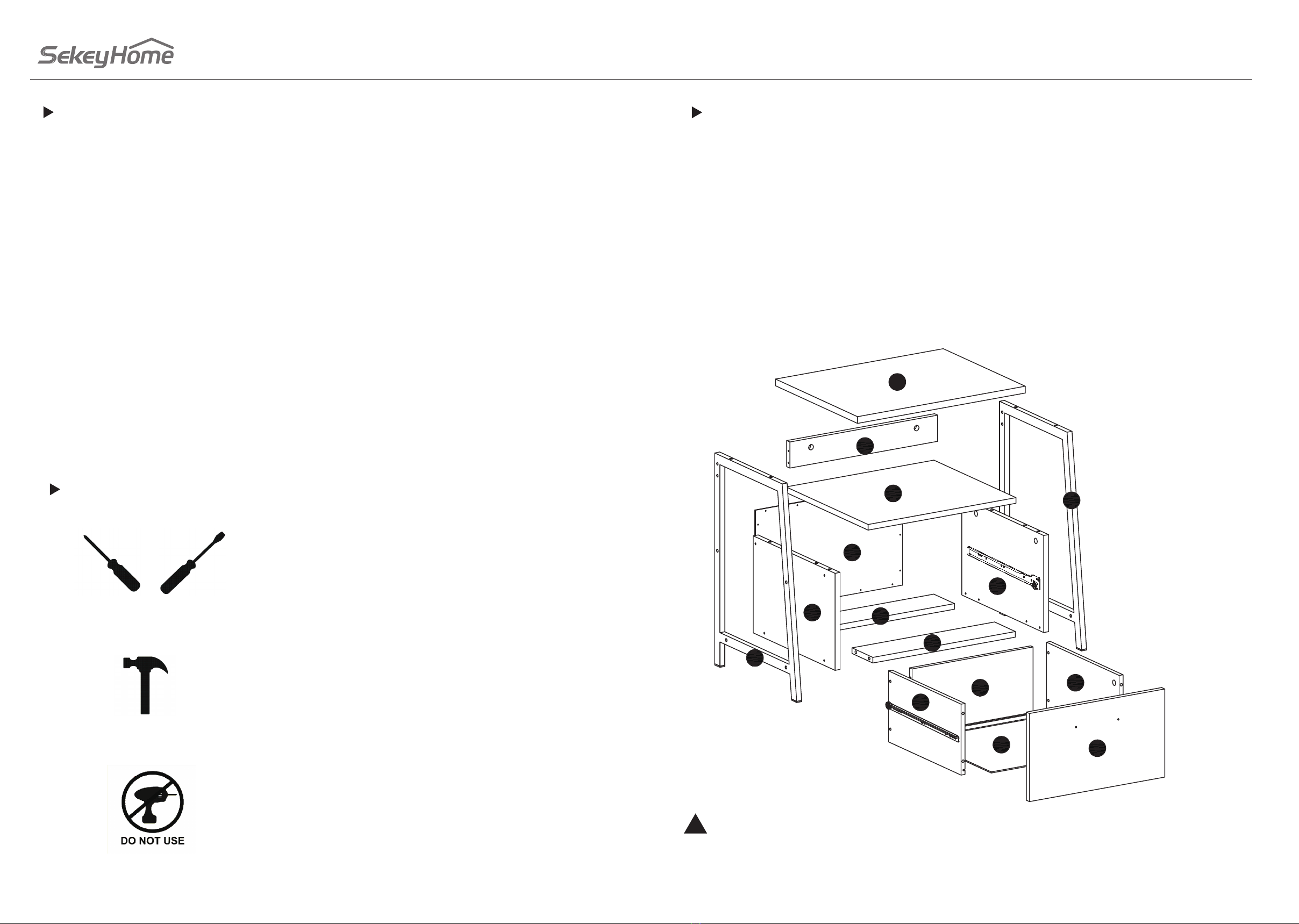
No. 2 Phillips Screwdriver and Flat head
screwdriver
Shown Actual Size
Hammer
Not actual size
Skip the power trip.
This time.
Part ldentication
1.TOP (1)
2.LEFT LEG (1)
3.RIGHT LEG (1)
4.LEFT END (1)
5.RIGHT END (1)
6. BRACE (2)
7. UPPER BACK (1)
8.SHELF (1)
9.LOWER BACK (1)
10.DRAWER FRONT (1)
11.LEFT DRAWER SIDE (1)
12.RIGHT DRAWER SIDE (1)
13.DRAWER BOTTOM (1)
14.DRAWER BACK (1)
Table of Contents
Assembly Tools Required
Part Identi cation 2
Hardware Identication 3
Assembly steps 4-20
Inhaltsverzeichnis 21-25
manuale di istruzioni 26-30
manual de instrucciones 31-35
Safety 36-39
Warranty 40-47
While not parts are labled,some of the parts will have a label or an inked letter on the edge to help
distinguish similar parts from each other.Use this part identication to help identify similar parts.
!
1
2
3
4
9
8
7
5
6
6
14
11
13 10
12

3 4
Hardware ldentication
A.CAM SCREW -14+1 B.HIDDEN CAM -14+1
C.Ø8x30WOOD DOWEL - 5+1 D. SMALL CAM SCREW - 4+1
E.SMALL HIDDEN CAM - 4+1 F.1-1/2''FLAT HEAD SCREW - 4+1
G.1" LARGE HEAD SCREW - 8+1 H.1-1/2''FLAT HEAD SCREW - 4+1
I. 7/8" MACHINE SCREW - 2+1 J.1-1/2" LARGE HEAD SCREW - 4+1
K.3/4''NALL - 16+1 L.PULL -1
M.APPLIQUE CARD - 3
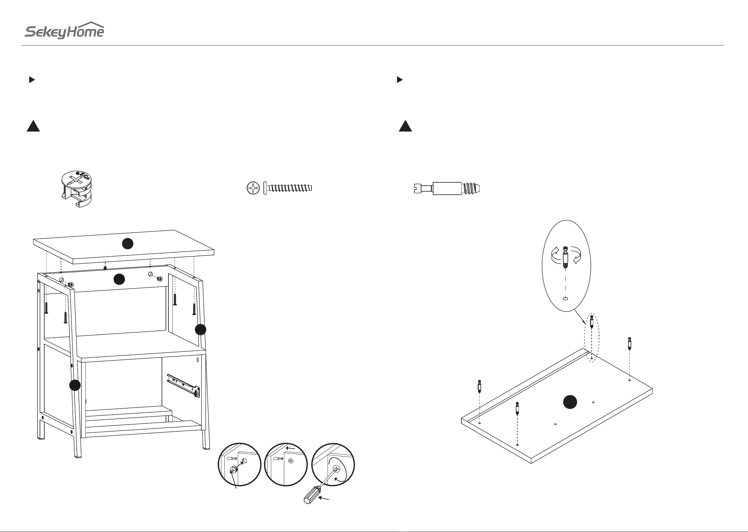
STEP 1
Assemble your unit on a carpeted oor or on the empty carton to avoid scratching your unit or the oor.
Turn eight CAM SCREW(A) to the END( 4 and 5).
Insert four WOOD DOWEL(C) to the END( 4 and 5).
4
A
A
A
A
C
C
C
C
5
A
A
AA
A
Finished edge
Finished edge
Finished edge
Unfinished edge
When assembling the components,
be sure to check which side is
finished edge.
When assembling the components, be sure to check whether the hole is consistent with the
corresponding position on the manual. If you need any help, please feel free to contact us via
info@sekeygroup.com.
!
A.CAM SCREW - 8 C.Ø8x30WOOD DOWEL - 4
5 6
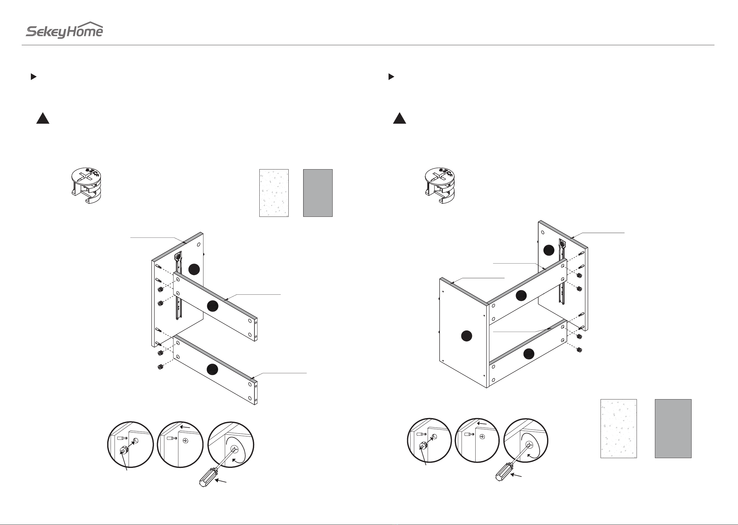
STEP 2
Fasten the BRACE(6) to the LEFT END(4), use four HIDDEN CAM(B).
Finished edge
Unfinished edge
When assembling the components,
be sure to check which side is
finished edge.
Flat head
screwdriver
123
The arrow must
point toward the
dege of the board.
Finished edge
Finished edge
4
6
6
B
B
B
B
Finished edge
When assembling the components, be sure to check whether the hole is consistent with the
corresponding position on the manual. If you need any help, please feel free to contact us via
info@sekeygroup.com.
!When assembling the components, be sure to check whether the hole is consistent with the
corresponding position on the manual. If you need any help, please feel free to contact us via
info@sekeygroup.com.
!
B.HIDDEN CAM - 4 B.HIDDEN CAM - 4
STEP 3
Fasten the BRACE(6) to the RIGHT END(5), use four HIDDEN CAM(B).
Finished edge
Unfinished edge
When assembling the components,
be sure to check which side is
finished edge.
Flat head
screwdriver
123
The arrow must
point toward the
dege of the board.
4
5
6
6
Finished edge
Finished edge
Finished edge
Finished edge
B
B
B
B

7 8
STEP 4
Turn four CAM SCREW(A) to the SHELF(8).
!
A.CAM SCREW - 8
8
A
A
A
A
A
STEP 5
Fasten the SHELF(8) to the END (4 and 5), use four HIDDEN CAM(B).
Finished edge
Unfinished edge
When assembling the components,
be sure to check which side is
finished edge.
Flat head
screwdriver
123
The arrow must
point toward the
dege of the board.
8
Finished edge
4
5
6
6
B
B
B
B
Finished edge
Finished edge
Finished edge
Finished edge
Finished edge
Finished edge
B.HIDDEN CAM -4
When assembling the components, be sure to check whether the hole is consistent with the
corresponding position on the manual. If you need any help, please feel free to contact us via
info@sekeygroup.com.
!When assembling the components, be sure to check whether the hole is consistent with the
corresponding position on the manual. If you need any help, please feel free to contact us via
info@sekeygroup.com.
!

9 10
STEP 6
Fasten the LOWER BACK(9) , use sixteen 3/4''NALL(K).
!
Finished edge
Unfinished edge
When assembling the components,
be sure to check which side is
finished edge.
8
4
5
6
9
1MM
1
9
1MM
1MM
Unfinished
edge Unfinished edge
K
Finished side
STEP 7
Turn two CAM SCREW(A) to the TOP(1) Insert one WOOD DOWEL(C) to the UPPER BACK(7).
1
7
A
C
A
A
K.3/4''NALL - 16 A.CAM SCREW - 2 C.Ø8x30WOOD DOWEL - 1
When assembling the components, be sure to check whether the hole is consistent with the
corresponding position on the manual. If you need any help, please feel free to contact us via
info@sekeygroup.com.
!When assembling the components, be sure to check whether the hole is consistent with the
corresponding position on the manual. If you need any help, please feel free to contact us via
info@sekeygroup.com.
!
11 12
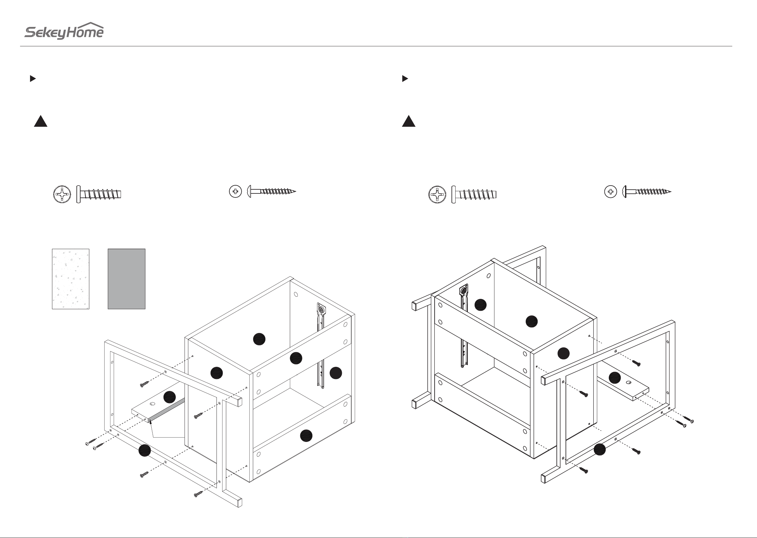
STEP 8
Fasten the LEFT LEG(2) to the LEFT END(4) and UPPER BACK(7), use four 1" LARGE HEAD SCREW(G)
and two 1-1/2''FLAT HEAD SCREW(H).
!
Finished edge
Unfinished edge
When assembling the components,
be sure to check which side is
finished edge. 8
4
7
edge
Finished
G
G
G
G
H
H
5
6
6
2
G.1" LARGE HEAD SCREW - 4 H.1-1/2''FLAT HEAD SCREW - 2 G.1" LARGE HEAD SCREW - 4 H.1-1/2''FLAT HEAD SCREW - 2
STEP 9
Fasten the RIGHT LEG(3) to the RIGHT END(5) and UPPER BACK(7), use four 1" LARGE HEAD SCREW(G)
and two 1-1/2''FLAT HEAD SCREW(H).
5
4
8
3
G
G
G
G
H
H
7
When assembling the components, be sure to check whether the hole is consistent with the
corresponding position on the manual. If you need any help, please feel free to contact us via
info@sekeygroup.com.
!When assembling the components, be sure to check whether the hole is consistent with the
corresponding position on the manual. If you need any help, please feel free to contact us via
info@sekeygroup.com.
!
13 14
STEP 10
Fasten TOP(1) to the LEG(2 and 3) and UPPER BACK(7), use four 1-1/2" LARGE HEAD SCREW(J) and two
HIDDEN CAM(B).
Flat head
screwdriver
123
The arrow must
point toward the
dege of the board.
1
7
2
3
JJ
JJ
B
B
B.HIDDEN CAM - 2 J.1-1/2" LARGE HEAD SCREW - 4
STEP 11
Turn four SMALL CAM SCREW(D) to the Drawer front (10).
D
D
D
D
10
D
When assembling the components, be sure to check whether the hole is consistent with the
corresponding position on the manual. If you need any help, please feel free to contact us via
info@sekeygroup.com.
!When assembling the components, be sure to check whether the hole is consistent with the
corresponding position on the manual. If you need any help, please feel free to contact us via
info@sekeygroup.com.
!
D. SMALL CAM SCREW - 4

15 16
STEP 12
Fasten the DRAWER SIDE(11 and 12) to the DRAWER FRONT (10), use four SMALL HIDDEN CAM (E)
!
Flat head
screwdriver
123
The arrow must
point toward the
dege of the board.
10
12
11
EE
E
E
STEP 13
E.SMALL HIDDEN CAM - 4
Insert the DRAWER BOTTOM(13) to the drawer side.
13
11
11
Finished side
When assembling the components, be sure to check whether the hole is consistent with the
corresponding position on the manual. If you need any help, please feel free to contact us via
info@sekeygroup.com.
!When assembling the components, be sure to check whether the hole is consistent with the
corresponding position on the manual. If you need any help, please feel free to contact us via
info@sekeygroup.com.
!
17 18
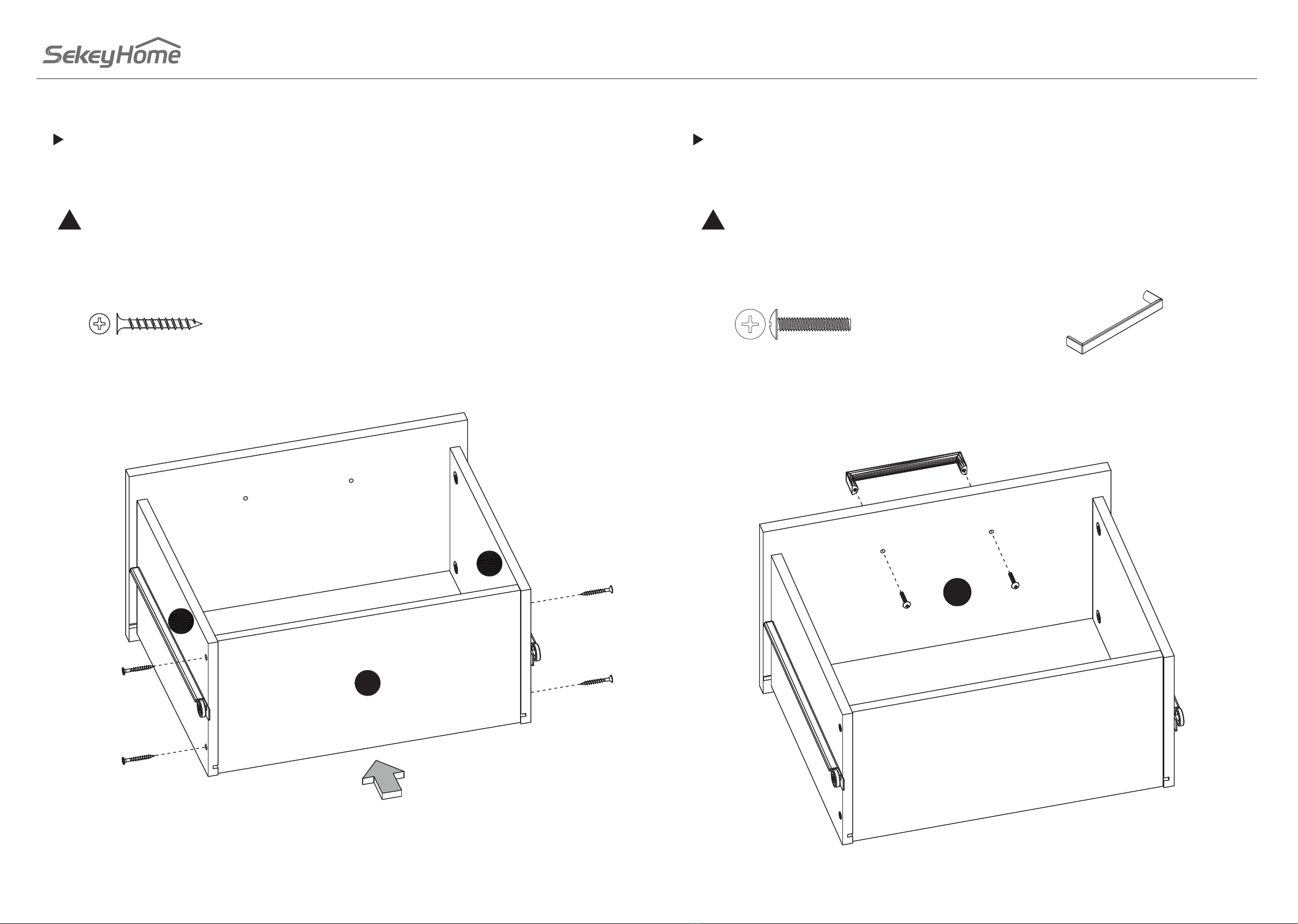
Fasten the DRAWER BACK(14) to the drawer side, use four 1-1/2''FLAT HEAD SCREW(F).
!
14
12
11
F
F
F
F
STEP 14 STEP 15
F.1-1/2''FLAT HEAD SCREW - 4
Fasten the PULL(L) to the DRAWER FRONT(10), use two 7/8" MACHINE SCREW (I).
L
II
10
L.PULL -1
I. 7/8" MACHINE SCREW - 2
When assembling the components, be sure to check whether the hole is consistent with the
corresponding position on the manual. If you need any help, please feel free to contact us via
info@sekeygroup.com.
!When assembling the components, be sure to check whether the hole is consistent with the
corresponding position on the manual. If you need any help, please feel free to contact us via
info@sekeygroup.com.
!
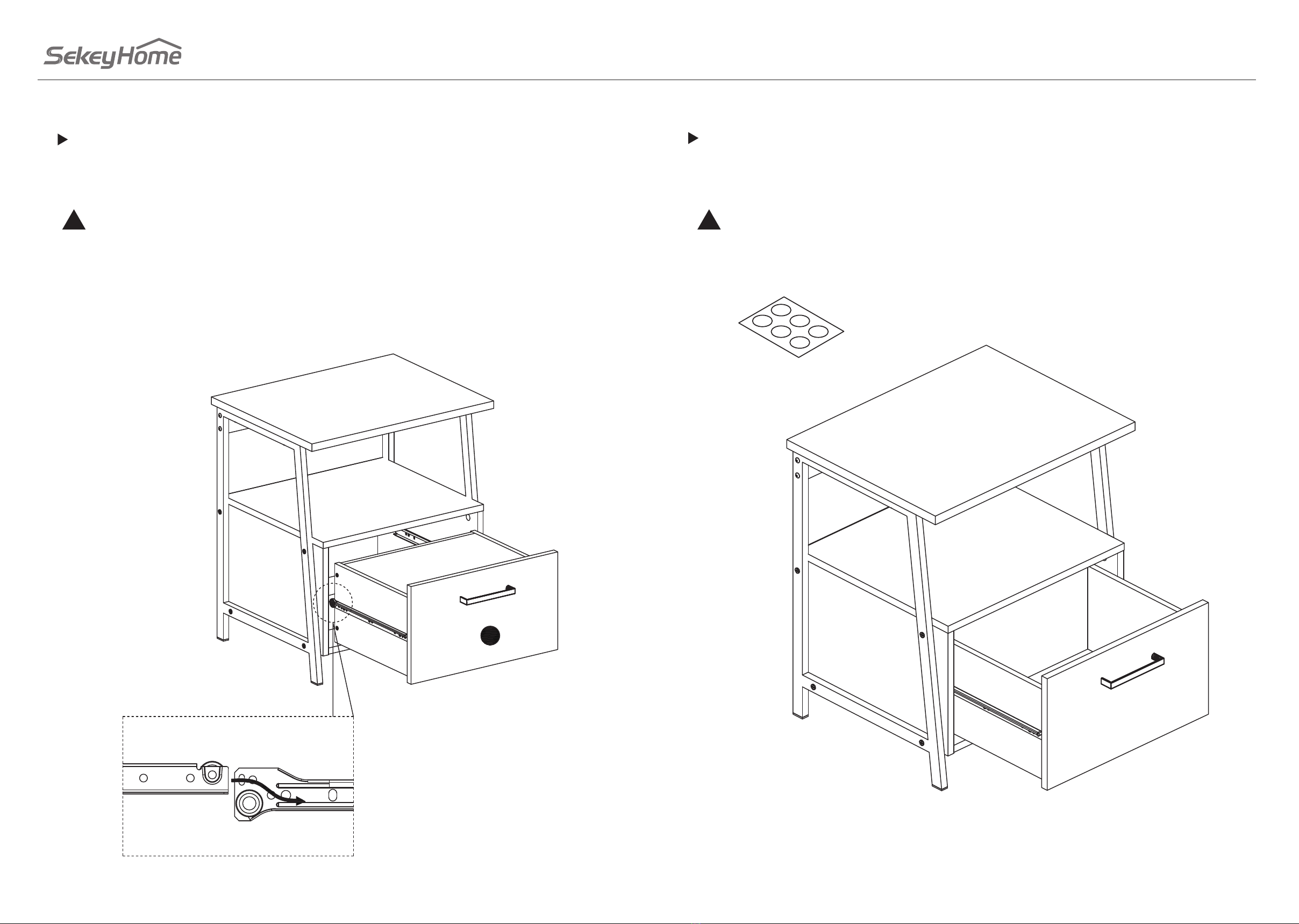
19 20
To insert the drawer into your unit, tip the front of the drawer down and drop the rollers on the
drawer behind the rollers on the unit. Lift the front of the drawer up and slide it into the unit.
!
STEP 16 STEP 17
Peel the COVERS from the SCREW COVER CARD (M) and stick one onto each visible SCREW head.
NOTE: Please read this back page of the instruction booklet for important safety information.
This completes assembly. Clean with your favorite furniture polish or a damp cloth. Wipe dry
30 lbs
25 lbs
15 lbs
M.APPLIQUE CARD - 3
When assembling the components, be sure to check whether the hole is consistent with the
corresponding position on the manual. If you need any help, please feel free to contact us via
info@sekeygroup.com.
!When assembling the components, be sure to check whether the hole is consistent with the
corresponding position on the manual. If you need any help, please feel free to contact us via
info@sekeygroup.com.
!

21 22
1. TISCHPLATTE (1)
2. RAHMEN links (1)
3. RAHMEN rechts (1)
4. SCHUBLADENSEITE links (1)
5. SCHUBLADENSEITE rechts (1)
6. STÜTZEN (2)
7. BLENDE (1)
8. REGALBODEN (1)
9. RÜCKSEITE (1)
10. SCHUBLADENVORDERSEITE (1)
11. SCHUBLADE links (1)
12. SCHUBLADE rechts (1)
13. SCHUBLADENBODEN (1)
14. SCHUBLADENRÜCKSEITE (1)
Stellen Sie das Regal auf einen Teppichboden oder auf einen leeren Karton, um Kratzer zu vermeiden.
Setzen Sie 8 der BOLZEN (A) in die beiden SCHUBLADENSEITEN (4 und 5). Setzen Sie 4 HOLZDÜBEL
(C) in die beiden SCHUBLADENSEITEN (4 und 5).
A. BOLZEN KORPUSVERBINDER – 8 C. HOLZDÜBEL - 4
Achten Sie beim Zusammenbau der Komponenten darauf, welche Seite mit der Kante
zusammengehört.
A.BOLZEN KORPUSVERBINDER -14+1
B.EXZENTERGEHÄUSE KORPUSVERBINDER -14+1
C. Ø 8x30 HOLZDÜBEL - 5+1
D.KLEINE BOLZEN KORPUSVERBINDER - 4+1
E.KLEINE EXZENTERGEHÄUSE KORPUSVERBINDER - 4+1
F. 1-1/2''FLACHKOPFSCHRAUBE - 4+1
G. 1" KOPFSCHRAUBE - 8+1
H. 1-1/2'' FLACHKOPFSCHRAUBE - 4+1
I. 7/8" SCHRAUBE - 2+1
J. 1-1/2" KOPSCHRAUBE - 4+1
K.3/4'' NAGEL - 16+1
L. GRIFF -1
M. SCHUTZABDECKUNGEN - 3
Obwohl keine Einzelteile beschriftet sind, weisen einige Teile an der Kante ein Etikett oder einen
eingefärbten Buchstaben auf, um Teile voneinander unterscheiden zu können. Verwenden Sie diese
Identikation, um ähnliche Teile zu identizieren.
!
Einzelteile SCHRITT 1
Befestigen Sie die STÜTZE (6) an der linken SCHUBLADENSEITE (4), benutzen Sie dazu 4 der
EXZENTERGEHÄUSE (B).
B. EXZENTERGEHÄUSE KORPUSVERBINDER - 4
Achten Sie beim Zusammenbau der Komponenten darauf, welche Seite mit der Kante
zusammengehört. Der Pfeil muss auf das Brett zeigen.
SCHRITT 2
Befestigen Sie die STÜTZE (6) an der rechten SCHUBLADENSEITE (5), benutzen Sie dazu 4 der
EXZENTERGEHÄUSE (B).
B. EXZENTERGEHÄUSE KORPUSVERBINDER - 4
Achten Sie beim Zusammenbau der Komponenten darauf, welche Seite mit der Kante
zusammengehört. Der Pfeil muss auf das Brett zeigen.
SCHRITT 3
Drehen Sie 4 der BOLZEN (A) in den REGALBODEN (8).
A. BOLZEN KORPUSVERBINDER - 4
SCHRITT 4
Zusatzmaterial

23 24
Befestigen Sie den REGALBODEN (8) an beiden SCHUBLADENSEITEN (4 und 5), benutzen Sie dazu 4
der EXZENTERGEHÄUSE (B).
B. EXZENTERGEHÄUSE KORPUSVERBINDER - 4
Achten Sie beim Zusammenbau der Komponenten darauf, welche Seite mit der Kante
zusammengehört. Der Pfeil muss auf das Brett zeigen.
SCHRITT 5
Befestigen Sie die RÜCKSEITE (9), benutzen Sie dazu 16 der 3/4'' Nägel (K).
K. 3/4'' Nagel - 16
Achten Sie beim Zusammenbau der Komponenten darauf, welche Seite mit der Kante
zusammengehört.
SCHRITT 6
Drehen Sie 2 der BOLZEN (A) in die TISCHPLATTE (1). Benutzen Sie 1 HOLZDÜBEL (C) für die BLENDE (7).
A. BOLZEN KORPUSVERBINDER – 2 C. HOLZDÜBEL - 1
SCHRITT 7
Befestigen Sie den linken RAHMEN (2) an der linken SEITE (4) und der BLENDE (7), benutzen Sie dazu
4 der 1" KOPFSCHRAUBEN (G) und 2 der 1-1/2'' FLACHKOPFSCHRAUBEN (H).
G. 1" KOPFSCHRAUBE – 4 H. 1-1/2'' FLACHKOPFSCHRAUBE - 2
Achten Sie beim Zusammenbau der Komponenten darauf, welche Seite mit der Kante
zusammengehört.
SCHRITT 8
Befestigen Sie den rechten RAHMEN (3) an der rechten SEITE (5) und der BLENDE(7), benutzen Sie
dazu 4 der 1" KOPFSCHRAUBEN (G) und 2 der 1-1/2'' FLACHKOPFSCHRAUBEN (H).
G. 1" KOPFSCHRAUBE - 4 H. 1-1/2'' FLACHKOPFSCHRAUBE - 2
SCHRITT 9
Befestigen Sie die TISCHPLATTE (1) an den RAHMENSEITEN (2 und 3) und der BLENDE (7), benutzen
Sie dazu 4 der 1-1/2" KOPFSCHRAUBEN (J) und 2 der EXZENTERGEHÄUSE (B).
J. 1-1/2" KOPFSCHRAUBE - 4 B. EXZENTERGEHÄUSE KORPUSVERBINDER -2
Der Pfeil muss auf das Brett zeigen.
SCHRITT 10
Benutzen Sie 4 der kleinen BOLZEN (D) für die SCHUBLADENVORDERSEITE (10).
D. KLEINE BOLZEN KORPUSVERBINDER - 4
SCHRITT 11
Befestigen Sie die beiden SCHUBLADENSEITEN (11 und 12) an der SCHUBLADENVORDERSEITE (10),
benutzen Sie dazu 4 der kleinen EXZENTERGEHÄUSE (E).
E. KLEINE EXZENTERGEHÄUSE KORPUSVERBINDER - 4+1
Der Pfeil muss auf das Brett zeigen.
SCHRITT 12
Setzen Sie den SCHUBLADENBODEN (13) in die SCHUBLADE ein.
SCHRITT 13
25 26
Befestigen Sie die RÜCKWAND der SCHUBLADE (14) am Rest, benutzen Sie dazu 4 der 1-1/2''
FLACHKOPFSCHRAUBEN (F).
F. 1-1/2'' FLACHKOPFSCHRAUBEN - 4
SCHRITT 14
Befestigen Sie den GRIFF (L) an der SCHUBLADENFRONT (10), benutzen Sie dazu 2 der 7/8"
Schrauben (I).
I.7/8" SCHRAUBE - 2 L.GRIFF - 1
SCHRITT 15
Um die Schubladen einzusetzen, kippen Sie die Vorderseite der Schublade nach unten und schieben
Sie die Rollen der Schublade über die des Tisches.
SCHRITT 16
Entnehmen Sie die SCHUTZABDECKUNGEN (M) und kleben Sie diese auf die sichtbaren
EXZENTERGEHÄUSE.
HINWEIS: Wichtige Sicherheitsinformationen nden Sie auf den Rückseiten der Bedienungsanleitung.
Damit ist die Montage abgeschlossen. Reinigen Sie das Regal mit einer Möbelpolitur oder einem
feuchten Tuch. Trocken wischen nicht vergessen.
M. SCHUTZABDECKUNGEN - 3
SCHRITT 17
1.PARTE SUPERIORE 1)
2.GAMBA SINISTRA (1)
3. GAMBA DESTRA (1)
4.FINE SINISTRA (1)
5.FINE DESTRA (1)
6. SOSTEGNO (2)
7. RETRO SUPERIORE (1)
8.MENSOLA (1)
9.RETRO INFERIORE (1)
10.CASSETTO FRONTALE (1)
11.LATO CASSETTO SINISTRO (1)
12.DESTRO CASSETTO LATO (1)
13.CASSETTO INFERIORE(1)
14.CASSETTO DIETRO (1)
A. UNA VITE A CAMME -14 + 1
B. CAMERA NASCOSTA -14 + 1
C. Ø8x30 DOWEL WOOD - 5 + 1
D. VITE A CAMME PICCOLE - 4 + 1
E. PICCOLA CAMERA NASCOSTA - 4 + 1
F. 1-1 / 2 '' VITE A TESTA PIATTA - 4 + 1
G. 1 "VITE A TESTA GRANDE - 8 + 1
H. VITE A TESTA PIATTA H.1-1 / 2 '' - 4 + 1
I.7 / 8 "VITE MACCHINA - 2 + 1
J.1-1 / 2 "VITE A TESTA GRANDE - 4 + 1
K. 3 / 4''VITI - 16 + 1
L. MANIGLIA -1
M.CARTA .APPLIQUE – 3
Identicazione parti
Identicazione hardware
Sebbene le parti non siano etichettate, alcune parti avranno un'etichetta o una lettera inchiostrata sul
bordo per aiutare a distinguere parti simili l'una dall'altra. Utilizzare questa parte di identicazione per
identicare parti simili.
!

27 28
Montare l'unità su un pavimento in moquette o sul cartone vuoto per evitare di graarla o di
graare il pavimento.
Ruotare otto VITI (A) verso le FINI (4 e 5).
Inserire quattro TASSELLI DI LEGNO (C) nelle FINI (4 e 5).
A. VITI -8 C. TASSELLI IN LEGNO - 4
Quando si assemblano i componenti, assicurarsi di controllare da che parte è nito il bordo.
PASSO 1
Fissare il SOSTEGNO (6) alla FINE SINISTRA (4), utilizzare quattro VITI (B). -4
Quando si assemblano i componenti, assicurarsi di controllare da che parte è nito il bordo.
La freccia deve puntare verso il margine della tavola.
Cacciavite a testa piatta
PASSO 2
Fissare il SOSTEGNO (6) alla FINE DESTRA (5), utilizzare quattro VITI (B). -4
Quando si assemblano i componenti, assicurarsi di controllare da che parte è nito il bordo.
La freccia deve puntare verso il margine della tavola.
Cacciavite a testa piatta
PASSO 3
Ruotare quattro VITI (A) su una MENSOLA (8).
VITI (A) -4
PASSO 4
Fissare la mensola (8) alle FINI (4 e 5), utilizzare quattro VITI (B).
Quando si assemblano i componenti, assicurarsi di controllare da che parte è nito il bordo.
La freccia deve puntare verso il margine della tavola.
Cacciavite a testa piatta
PASSO 5
Fissare il RETRO INFERIORE (9), utilizzare sedici 3 / 4''NALL (K).
K. 3 / 4''NALL - 16
Quando si assemblano i componenti, assicurarsi di controllare da che parte è nito il bordo.
PASSO 6
Ruotare due VITI (A) verso l'alto (1)
Inserire un TASSELLO IN LEGNO (C) nella PARTE SUPERIORE (7).
VITI-2
TASSELLI DI LEGNO -2 C –
PASSO 7
Fissare la GAMBA SINISTRA (2) a FINE SINISTRA (4) e alla SCHIENA SUPERIORE (7), utilizzare quattro
VITI testa grande
VITE (G) e due VITI A TESTA PIATTA 1-1 / 2 '' (H).
G.1 "VITE A TESTA GRANDE - 4 H.1-1 / 2 '' VITE A TESTA PIATTA - 2
Quando si assemblano i componenti, assicurarsi di controllare da che parte è nito il bordo.
PASSO 8
Fissare la GAMBA DESTRA (3) alla FINE DESTRA (5) e allo SCHIENALE SUPERIORE (7), utilizzare quattro
VITI G) e due VITI(H).
G.1 "VITE A TESTA GRANDE - 4
VITE A TESTA PIATTA H.1-1 / 2 '' - 2
PASSO 9
Fissare LA PARTE SUPERIORE (1) alle GAMBE (2 e 3) e ALLO SCHIENALE SUPERIORE (7), utilizzare quattro
TESTE GRANDI 1-1 / 2 "
VITE (J) e due VITI (B).
J.1-1 / 2 "VITE A TESTA GRANDE - 4
B VITI CAM NASCOSTE -2
La freccia deve puntare verso il margine della tavola.
Cacciavite a testa piatta
PASSO 10

29 30
Ruotare quattro VITI PICCOLE (D) in avanti sul cassetto (10).
D VITE A CAMME PICCOLE - 4
STEP 12
PASSO 11
Fissare il CASSETTO LATERALE DESTRO (11 e 12) al CASSETTO FRONTALE (10),
utilizzare quattro VITI (E)
E. VITI - 4
La freccia deve puntare verso il bordo della tavola.
Cacciavite a testa piatta
PASSO 12
Inserire il CASSETTO INFERIORE (13) sul lato del cassetto.
PASSO 13
Fissare il CASSETTO RETROK (14) sul lato del cassetto,
utilizzare quattro VITI' (F).
VITI (F) – 4
PASSO 14
Fissare il PULL (L) al CASSETTO FRONTALE (10),
utilizzare due VITI"(I).
VITI (I)- 2
L. VITE - 1
PASSO 15
Per inserire il cassetto nell'unità, inclinare verso il basso la parte anteriore del cassetto e rilasciare I
rulli sul cassetto dietro i rulli sull'unità. Sollevare la parte anteriore del cassetto
e farlo scorrere nell'unità.
PASSO 16
Sbucciare i COPERCHI dalla CARTA PROTETTIVA SUPERIORE (M) e attaccarne uno su ciascuno visibile
Testa a VITE.
NOTA: leggere questa pagina posteriore del libretto di istruzioni per importanti informazioni sulla
sicurezza.
Questo completa l'assemblaggio. Pulisci con il tuo smalto per mobili preferito o un panno umido.
Asciugare
CARTA.APPLIQUE - 3
PASSO 17

32
1. TAPA (1)
2. PATA IZQUIERDA (1)
3. PATA DERECHA (1)
4. TERMINAL IZQUIERDO (1)
5. TERMINAL DERECHO (1)
6. REFUERZO (2)
7. TRASERA SUPERIOR (1)
8. ESTANTE (1)
9. TRASERA INFERIOR (1)
10. FRONTAL DE CAJÓN (1)
11. LATERAL IZQUIERDO CAJÓN (1)
12. LATERAL DERECHO CAJÓN (1)
13. BAJO CAJÓN (1)
14. TRASERA CAJÓN (1)
Monte su producto sobre un suelo alfombrado o sobre la caja de cartón vacía para evitar rayar el
producto o el suelo.
Gire ocho PERNO (A) al TERMINAL (4 y 5).
Inserte cuatro ESPIGA DE MADERA (C) al TERMINAL (4 y 5).
A. PERNO -8 C. ESPIGA DE MADERA - 4
Al ensamblar los componentes, asegúrese de vericar qué lado está terminado.
A. PERNO -14+1
B. EXCÉNTRICA -14+1
C. ESPIGA DE MADERA Ø8x30 - 5+1
D. PERNO PEQUEÑO - 4+1
E. EXCÉNTRICA PEQUEÑA - 4+1
F. TORNILLO DE CABEZA PLANA 1-1/2'' - 4+1
G. TORNILLO DE CABEZA GRANDE 1" - 8+1
H. TORNILLO DE CABEZA PLANA 1-1/2'' - 4+1
I. TORNILLO PARA METAL 7/8" - 2+1
J. TORNILLO DE CABEZA GRANDE 1-1/2" - 4+1
K.CLAVO 3/4'' - 16+1
L. TIRADOR -1
M. TARJETA DE EMBELLECEDORES (TAPA TORNILLOS) - 3
Identicación de partes PASO 1
Fije el REFUERZO (6) al TERMINAL IZQUIERDO (4), use cuatro EXCÉNTRICA (B).
B. EXCÉNTRICA -4
Al ensamblar los componentes, asegúrese de vericar qué lado está terminado.
La echa debe apuntar hacia el borde del tablero.
Destornillador de cabeza plana
PASO 2
Fije el REFUERZO (6) al TERMINAL DERECHO (5), use cuatro EXCÉNTRICA (B).
B. EXCÉNTRICA -4
Al ensamblar los componentes, asegúrese de vericar qué lado está terminado.
La echa debe apuntar hacia el borde del tablero.
Destornillador de cabeza plana
PASO 3
Gire cuatro PERNO (A) al ESTANTE (8).
A. PERNO -4
PASO 4
Identicación de tornillería / hardware
31
Si bien no se etiquetan las partes, algunas de ellas tendrán una etiqueta o una letra entintada en el
borde para ayudar a distinguir partes similares entre sí. Use esta identicación de parte para ayudar
a identicar partes similares.
!
33 34
Fije el ESTANTE (8) al TERMINAL (4 y 5), use cuatro EXCÉNTRICA (B).
B. EXCÉNTRICA -4
Al ensamblar los componentes, asegúrese de vericar qué lado está terminado.
La echa debe apuntar hacia el borde del tablero.
Destornillador de cabeza plana
PASO 5
Fije la TRASERA INFERIOR (9), use dieciséis CLAVO 3/4'' (K).
K. CLAVO 3/4'' - 16
Al ensamblar los componentes, asegúrese de vericar qué lado está terminado.
PASO 6
Gire dos PERNO (A) en la TAPA (1)
Inserte una ESPIGA DE MADERA (C) a la TRASERA SUPERIOR (7).
A. PERNO -2 C. ESPIGA DE MADERA - 1
PASO 7
Fije la PATA IZQUIERDA (2) al TERMINAL IZQUIERDO (4) y TRASERA SUPERIOR (7), use cuatro TORNILLO
DE CABEZA GRANDE 1" (G) y dos TORNILLO DE CABEZA PLANA 1-1/2'' (H).
G. TORNILLO DE CABEZA GRANDE 1" - 4
H. TORNILLO DE CABEZA PLANA 1-1/2'' - 2
Al ensamblar los componentes, asegúrese de vericar qué lado está terminado.
PASO 8
Fije la PATA DERECHA (3) al TERMINAL DERECHO (5) and TRASERA SUPERIOR (7), use cuatro TORNILLO
DE CABEZA GRANDE 1" (G) y dos TORNILLO DE CABEZA PLANA 1-1/2'' (H).
G. TORNILLO DE CABEZA GRANDE 1" - 4
H. TORNILLO DE CABEZA PLANA 1-1/2'' - 2
PASO 9
Fije la TAPA (1) a la PATA (2 y 3) y TRASERA SUPERIOR (7), use cuatro TORNILLO DE CABEZA GRANDE
1-1/2" (J) y dos EXCÉNTRICA (B).
J. TORNILLO DE CABEZA GRANDE 1-1/2"- 4
B. EXCÉNTRICA -2
La echa debe apuntar hacia el borde del tablero.
Destornillador de cabeza plana
PASO 10
Gire cuatro PERNO PEQUEÑO (D) al FRONTAL DE CAJÓN (10).
D. PERNO PEQUEÑO - 4
PASO 11
Fije el LATERAL CAJÓN (11 y 12) al FRONTAL DE CAJÓN (10),
use cuatro EXCÉNTRICA PEQUEÑA (E)
E. EXCÉNTRICA PEQUEÑA - 4
La echa debe apuntar hacia el borde del tablero.
Destornillador de cabeza plana
PASO 12

35 36
Inserte el BAJO CAJÓN (13) en el LATERAL CAJÓN (11 y 12).
PASO 13
Fije la TRASERA CAJÓN (14) al LATERAL CAJÓN,
use cuatro TORNILLO DE CABEZA PLANA 1-1/2'' (F).
F. TORNILLO DE CABEZA PLANA 1-1/2'' - 4
PASO 14
Fije el TIRADOR (L) en el FRONTAL DE CAJÓN (10),
use dos TORNILLO PARA METAL 7/8" (I).
I. TORNILLO PARA METAL 7/8" - 2 L.TIRADOR - 1
PASO 15
Para insertar el cajón en su unidad, incline la parte delantera del cajón hacia abajo y deje caer los
rodillos del cajón detrás de los rodillos de la unidad. Levante la parte frontal del cajón y deslícelo
hacia la unidad.
PASO 16
Despegue las CUBIERTAS/EMBELLECEDORES de la TARJETA DE EMBELLECEDORES (M) y pegue una en
cada cabeza del TORNILLO visible.
NOTA: Por favor, lea las páginas posteriores del folleto de instrucciones para obtener información
importante sobre seguridad.
Esto completa el montaje. Limpie con su limpiador de muebles favorito o un paño húmedo. Secar.
M. TARJETA DE EMBELLECEDORES - 3
PASO 17
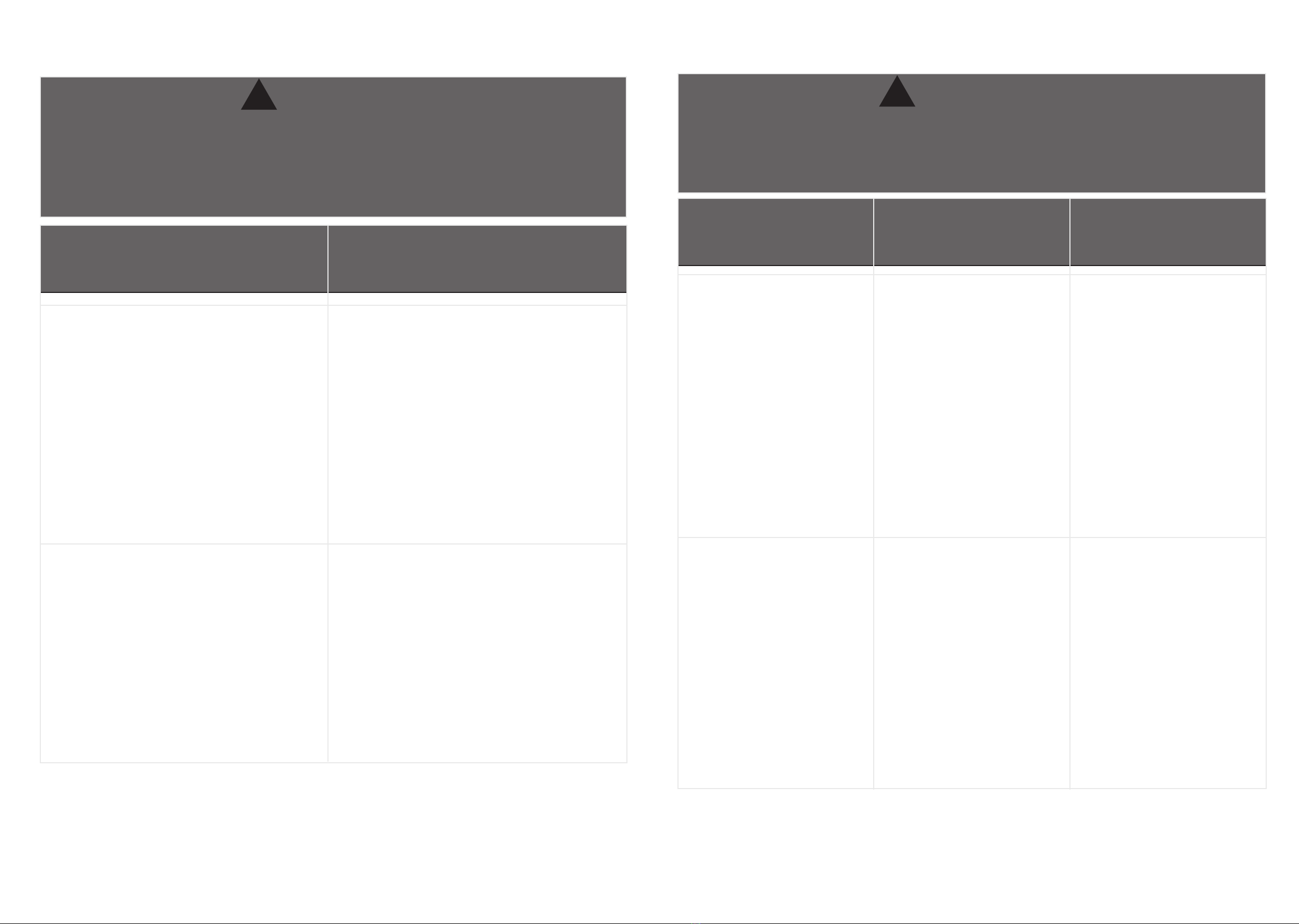
Warning
!
Overloaded shelves.
Risk of injury.
Top-heavy furniture can tip
over.
Overloaded shelves can
break.
Never exceed the weight
limits shown in the
instructions.
Work from bottom to top
when loading shelves.
Place the heavier items on
the lower shelves.
This product is not designed
to support a television.
Risk of injury or death. TVs
can be very heavy.Plus the
weight and location of the
picture tube tends to make
TVs unbalanced and prone
to tipping forward.
Placing TVs on furniture
items that are not designed
to support a television is
hazardous.
Look out for: What can happen: How to avoid the
problem:
Please use your furniture correctly and safely. Improper use can cause safety hazards,
or damage to your furniture or household items.Carefully read the following chart.
37 38
Warnung
!
Vermeiden Sie zu schwer beladene
Regalteile und Schubläden. Überladene
Regale können brechen.
Der Tisch kann durch falsche
Gewichtsverteilung kopastig werden und
kippen.
Überschreiten Sie bitte niemals die in der
Anleitung angegebenen Gewichtsgrenzen.
Arbeiten Sie beim Beladen von Regalen
und Schubläden von unten nach oben.
Legen Sie die schwereren Gegenstände in
die unteren Regale oder in die unteren
Schubläden.
Schieben Sie keine Möbel, besonders nicht
auf Teppichböden. Stützen Sie den
mittleren Abschnitt der Oberseite ab, wenn
Sie den Tisch anheben. Dieser Tisch ist nicht
als Fernsehtisch geeignet!
Die unsachgemäße Nutzung und das
Aufstellen von beispielsweise TV-Geräten
kann zur Verletzungsgefahr führen.
Fernsehgeräte können sehr schwer sein,
daher kann das Gewicht und die Position
des Bildschirmes dazu führen, dass das
Fernsehgerät neigt nach vorn zu kippen.
Achtung: So vermeiden Sie das Problem:
Bitte benutzen Sie Ihre Möbel richtig und sicher. Unsachgemäße Verwendung kann
zu Sicherheitsrisiken oder Schäden an den Möbeln oder anderen
Haushaltsgegenständen führen. Lesen Sie die folgende Tabelle bitte sorgfältig
durch und beachten Sie die Hinweise
Attenzione
!
Scaali sovraccaricati.
Rischio di infortunio.
I mobili pesanti possono
rovesciarsi.
Gli scaali sovraccarichi
possono rompersi.
Non superare mai i limiti
di peso indicati nelle
istruzioni.
Rischio di lesioni o morte. I
televisori possono essere
molto pesanti. Più il peso e
la posizione del tubo
dell'immagine tendono a
rendere i TV sbilanciati e
inclini a inclinarsi in avanti.
Lavora dal basso verso l'alto
quando carichi gli scaali.
Posizionare gli oggetti più
pesanti sui ripiani inferiori.
Questo prodotto non è
progettato per supportare
un televisore.
Posizionare i televisori su
mobili non progettati per
supportare un televisore è
pericoloso.
Fate Attenzione a Cosa può succedere: Come evitare il
problema:
Si prega di utilizzare il vostro arredamento in modo corretto e sicuro. L'uso improprio
può causare rischi per la sicurezza o danni ai mobili o articoli per la casa. Leggere
attentamente la seguente tabella.
Table of contents
Popular Indoor Furnishing manuals by other brands


Safco
Safco Rumba 2048 Assembly instructions

A.R.T. Furniture
A.R.T. Furniture 245204 Assembly instructions

Costway
Costway HU10155DK-T user manual

Home Decorators Collection
Home Decorators Collection RCGRW2830 Use and care guide

Jensen
Jensen DREAM Assembly and instructions for use

fantastic furniture
fantastic furniture HAMILTON Desk 3 Drawer manual