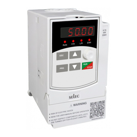
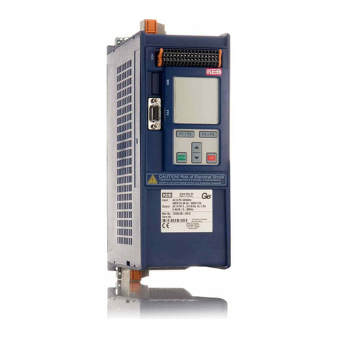
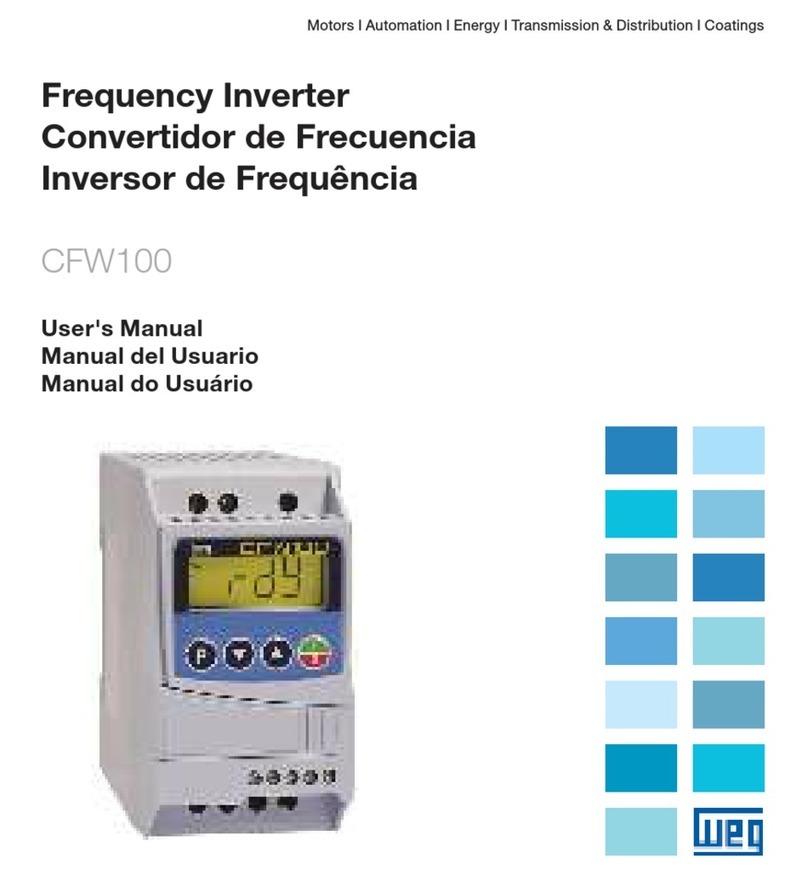
Selec VFD Series User manual

Compact & Powerful
VFD Series

User Manual Preface
PREFACE
The VFD-L series of drives focuses on providing you with the best levels of scalar control of
asynchronous AC motors. Through the adoption of the most advanced PWM technologies driven
through one of the most powerful DSP control systems, this drive is armed with optimized functions and
flexibility to drive a myriad of applications with stable performances as per your requirements.
This manual is enclosed as an attachment. We request you to keep it safely considering its importance in
commissioning, inspecting, and maintaining the product. In the pursuit of constant improvement, kindly
note, that this manual is subject to modifications without any notice.
To utilize the drive to its full function and ensure the safety of both users and the product, please read this
manual carefully before using the drive. Any incorrect operations may lead to fault, malfunction or
shortened lifetime, even damage to the device or the people around it.
Thank you very much for choosing the VFD-L series high-performance Variable Frequency Drives
(VFD). This manual will provide you with the detailed steps and precautions regarding installation, wiring,
setting of functional parameters, routine maintenance, malfunction diagnosis and solution etc.

User Manual
CONTENTS
Contents
4.5 Illustrations of keyboard operations- 13
P0- Basic Functional Parameters 16
6. Specifications of functional parameters 16
4.3 Function LEDs descriptions- 12
4.4 Keys Description- 12
5-1-2 Commissioning 14
P1- Keypad Parameters 17
5-1-1 Check before running 14
5-1-3 Quick Commissioning 15
6-1 Functional Parameters Table 16
P4- Scalar Control Parameters 19
4.2 Units LEDs descriptions- 12
5. Running 14
5-1 Commissioning 14
4.1 Illustration of Keypad 11
P2- Start and Stop Parameters 18
P3- Motor Parameters 19
4. Keyboard and Panel 11
P6- Output Function Parameters 21
P5- Input Function Parameters 20
P7- PI Control Parameters 22
1.1 Warning 5
1.2 Safety guidelines 5
2. Installation 6
2.1 Installation environment 6
2.2 Installation instructions and space limit 6
3. Wiring 7
3-2 Standard Wiring Diagram 8
3-3 Description of Terminals 9
3-3-1 Connection of Input Power Terminals 9
1.3 Delivery and Installation 5
3-1 Connection methods for assorted devices 7
3-3-2 Connection of Output Power Terminals 9
1. Safety precautions 5
3-3-3 Earth terminal PE 10
3-4 Explanation of control loop terminals 10

User Manual
P9- Protection Parameters 24
Pb- Communication parameters 26
PC- Enhanced Parameters 26
6-2 Detailed Explanation of Functional Parameters- 27
PA- Fault History 25
P1- Keypad Parameters 30
P2- Start and Stop Parameters 32
P8- Simple PLC and multispeed options 23
P3- Motor Parameters 36
P4- Scalar Control Parameters 36
P5- Input Function Parameters 39
P6- Output Function Terminals 45
P7- PI Control Parameters 47
P8- Simple PLC and Multispeed parameters 49
P9- Protection Parameters 52
P0- Basic Parameters 27
9.5 Read-write rules of parameter address for function code 67
PA- Fault History 55
Pb- Communication Parameters 55
10. Appendix 68
10.2 Product Dimensions 70
8.4. Product Warranty 62
9.3. Frame Structure 64
8.1. General maintenance and upkeep 61
8.2. Inspection and replacing damaged parts 61
7.2. Common Faults and processing schemes 60
9.4 Command code and data description 65
8.3. Storage 62
8. Maintenance 61
9.1. Protocol Content 63
7.1 Malfunction and solutions 59
10.1 Specifications 68
PC- Enhanced parameters 56
7. Fault Handling And Troubleshooting 59
9. External Communication 63
9.2. Protocol Instructions 63
Contents

5
1. Safety Precautions
• In any case, AC power lines SHOULD NOT be connected to the output terminals viz. U, V or W.
ŸPlease check for any damage caused during the transportation.
People working on the device should take part in professional electrical and safety training, receive
the certification and be familiar with all steps and requirements of installing, commissioning, operating
and maintaining the device to avoid any hazards.
• Ground wire must be connected correctly.
Read this manual carefully and follow all safety precautions before moving, installing, operating and
servicing the variable-frequency drive (VFD). Ignoring the safety protocols can result in damage or
loss of life or property.
1.2 Safety guidelines
• Only qualified professional engineers are allowed to assemble, wire, commission, or maintain the
converter.
ŸPower must be shut off completely before performing any kind of wiring on the control or power
terminals.
• Do not touch the internal components for your own and the product’s safety.
• Do not conduct the procedure of inspection or maintenance until the drive has been shut down for
at least 3 minutes or as mentioned on the drive terminal cover.
• No permission is granted to change or modify the internal components or circuits.
1.1 Warning
• The drive must be installed in an appropriate operating environment and far away from humidity or
water drops; care must be taken to protect it from direct sunlight or being overheated.
1.3 Delivery and Installation
Pre-delivery inspection for each drive is implemented strictly by our QC Department. The packaging
is adequately strengthened with special packing materials which to protect it from justifiable levels of
harm that could come its way during handling and transportation. However, as an added precaution,
we request you to kindly check the following points upon receipt of the device-
ŸPlease check if you have received the right converter accessories as per your order.
ŸPlease check if this is the model of the product for which you placed an order.
ŸPlease check if the enclosed documents are all inside the case namely the manual and test report.
User Manual

6
2. Installation
ŸThe ambient temperature should be -10°C ~ +50°C. Sufficient ventilation should be available.
• Spare space must be ensured for the ventilation of the drive to allow it to maintain its temperature
during operation.
• Ventilation must be taken into consideration to ensure that ambient temperature is lower than the
specified value when the drive is installed inside a control cabinet.
• It should be mounted by screws vertically; upside-down, slant or horizontal mountings are not allowed.
2.1 Installation environment
• It should be installed on a fire and heatproof frame, for example, a metal frame, to prevent risks of a fire
hazard.
ŸThere shouldn’t be any metal particulates in the surrounding air
ŸThe surroundings must be free from dust, caustic/corrosive/inflammable gases/liquids
ŸSolid base without vibrations.
2.2 Installation instructions and space limit
• To minimize the heat effect on each other, if two or more converters are installed in the same control
cabinet, they should be installed horizontally abreast; A baffle plate must be set up between them if, for
some reason, they have to be installed vertically.
50mm 50mm
≥100mm
≥100mm
UP
Right
CONVERTER
User Manual
CONVERTER
CONVERTER

7
3.WIRING
PE earth terminal must be connected with the ground.
For the safety of the operator as well as devices, only the professional engineers are allowed to
operate it. Please pay attention to the following precautions while wiring.
Power must be shut off before wiring.
The rated voltage must conform to AC voltage. Power cords must be connected with the terminal
R, S and T while motor lines should be connected with terminal U, V and W; any incorrect
connection may cause damage to the internal components of the converter.
The reliability of the terminals and wires must be evaluated before wiring, and screws for the
terminals of the major loop must be fastened solidly.
To avoid electric shock, do not touch the terminals of the major loop.
User Manual
3-1 Connection methods for assorted devices
Configuration
L U
N
V
W
M
Single - Phase
Power Source
Chopper AC reactor Electromagnetic
contactor Filter Filter
Name
Applicable
model should
be selected; its
rated current
must be no
less than 1.5
times the
rated current
of converter
it’s applied
to the
improvement
of input
power factors
it’s used to
control the
switching of
power source
it’s used to
reduce the
radio interfere-
nce generated
by converter
It’s used to reduce the
radio interference genera-
ted by converter. But it’s
not applicable if the leads
is too short
Descriptions

3-2 Standard Wiring Diagram
8
User Manual
Single phase supply source 230V ± 15%
Main Circuit
Control Circuit
GND
For NPN
Forward Jog
External Fault I/P
For PNP(Default)
L L
N N
Forward Rotation
Reverse Rotation
Grounding of Power
Measurments
Motor Grounding
Default Settings
AI2
AI1
GND
Input 0-20mA
Potentiometer
QE
NC
COM
NO
3
5
7
485+
485-
Output of relay
Default setting:
Fault output
1
Potentiometer Input
Multi-functional AI
Input 0-10V

9
3-3 Description of Terminals
Terminal symbol (code) Functional descriptions
Terminals for Single-phase AC input 220V
Output terminals, connect with three-phase AC electromotor
Terminal of ground (Earth terminal)
L,N
U, V, W
For safety's sake, please connect wires according to the regulations of National Electrical Code while
proceeding wiring.
3-3-1 Connection of Input Power Terminals
An additional breaker/chopper must be connected in series with the terminals of the major loop (L, N
and U, V, W). For better running, an electromagnetic contactor should be connected with them in series
so that it could cut off the power while the protection function of the converter is activated (Tip: R-C surge
absorbers should be added to the ends of the electromagnetic contactor). If an additional earth leakage
circuit breaker (ELCB) is installed as a protective device for electric leakage, the sensitivity of current
should be more than 200mA while actuation time should be no less than 0.1 second to prevent ELCB
from malfunctioning. AC reactor must be connected with the input terminals in cases were the rectifiers
could be damaged by high-voltage and high-current input from the grid, which could also improve the
input power factors. Do not control the converter by disconnecting the major loop. Instead of that,
RUN/STOP buttons on the keyboard or control loop terminals should be applied to the control of the
converter; if it has to be controlled by that way, it can be implemented only once every one hour. It's
feasible to reduce the interference with devices nearby by connecting an additional noise filter with the
input terminals. Do not connect converter driven by three-phase power to single-phase source.
3-3-2 Connection of Output Power Terminals
Output terminals must be connected to the three-phase motor in the correct order; if the motor
rotates in the wrong direction, any two wires among U, V and W electrical wiring can be switched with
each other. In any case, do not connect output terminals to a phasing capacitor or surge-absorber. When
the length of wire connecting converter with motor is more than 50 meters, there may be a large amount
of electric leakage caused by the capacitors between the wiring, which may lead to over current;
additionally, to protect the insulation of motor from being damaged, an additional output reactor must be
installed. An additional noise filter can be installed to reduce the electromagnetic interference of output if
surroundings can be easily affected by the converter; interference can also be minimized by reducing its
carrier frequency.
User Manual

3-3-4 Earth terminal PE
For safety's sake, earth terminal PE must be well grounded to reduce noise. Please use the
standard ground lead which should be as short and thick as possible (its grounding impedance should be
no more than 10Ω). Do not connect its ground lead with that of a high-current loading machine to the
ground at the same time, for example, welder or high-power motor, they must be grounded separately.
All the converters must be connected to the same earth terminal directly if two or more converters are
installed together; please refer to the wiring layout below
(a) correct (b) not recommend (c) error
10
User Manual
3-4 Explanations of control loop terminals
AI1 AI2 GND +V X1 X2 X3 X4 GND NC COM NO
Items Symbol Terminal Name Description/ Default Setting
1 AI1 Analog Input Terminal Terminal for Analog Input (0-20 mA)
signal
2 AI2 Analog Input Terminal Terminal for Analog Input (0-10 V) /
POT (0-24 V) signal
5GND Control Terminals Ground Ground for control terminals
6X1 Multifunction Input Terminal 1 Default Setting: FWD
7X2 Multifunction Input Terminal 2 Default Setting: REV
8 X3 Multifunction Input Terminal 3 Default Setting: FWD JOG
9X4 Multifunction Input Terminal 4 Default Setting: Ext Fault
10
11
GND Control Terminals Ground Ground for control terminals
12
13
+V 24V supply +24VDC / 50mA
14 NO Multifunction Relay Output NO terminal
Default setting: Fault Output
COM Multifunction Relay Output COM terminal
NC Multifunction Relay Output NC terminal

Multi-core shielded cable or stranded wire should be used to connect control terminals. The terminal
which is closed to the converter must be connected to earth terminal PE. When wiring, the control cables
must be kept away from the main circuit and high-current circuit by at least 30cm. Instead of parallel
wiring, vertical wiring should be adopted to prevent the drive from malfunctions resulting from external
interference.
11
User Manual
4. Keyboard and Panel
4.1 Illustration of Keypad
4.2 Units LEDs descriptions
LED Function
VDenotes that the value being shown is a voltage
A Denotes that the value being shown is a current
Hz Denotes that the value being shown is a frequency

4.3 Function LEDs descriptions
LED Function
RUN Denotes that the drive is in RUN operation
F/R Denotes the direction of operation of the drive.
OFF - Forward ON - Reverse
L/R
Denotes the source of control for the drive.
OFF - Local control using the keypad , ON - Remote control
ERR
Denotes presence of error condition
BLINKING - Pre-alarm condition triggered
STEADY - Fault condition triggered
12
User Manual
4.4 Keys Description
ESC 1. Go to the previous programming level,
2. Cycle online display pages
PRG 1. Enter Programming menu, 2. Save setting value
RUN/STP
1. Start Drive operation
2. Stop Drive operation
3. Fault Reset
Panel encoder 1. Clockwise- increment frequency being shown on screen
2. Anti-Clockwise- decrement frequency being shown on screen
1. Increment displayed editable value
2. Decrement displayed editable value
LED Function
Up key ( )
Down key ( )

4.5 Illustrations of keyboard operations
13
User Manual

ŸDo not connect the unit to the power supply until the enclosure is assembled and closed.
ŸIts default running mode is to be controlled through the keyboard and panel.
5-1-1 Check before running
ŸPlease confirm that there is no short circuit between terminals or any exposed charged
component.
ŸPlease check whether the wiring is correct or not, especially output terminals (U, V, W) which
mustn't be connected to the power source; additionally, earth terminals PE must be well-grounded
as well.
ŸIt is recommended to use appropriately sized lugs instead of free wires to prevent rogue strands
from creating a short between adjacent terminals.
5-1-2 Commissioning
ŸPlease confirm that all the components, such as terminals, pluggable connectors, or screws are
fastened.
ŸThe drive wirings must be checked and confirmed comprehensively before commissioning.
ŸIt is recommended that post initial settings, the user start by checking the jogging function. The
default jog frequency is 5.0Hz.
5-1 Commissioning
ŸMake sure that all the switches are off before it's connected to a power source, and that the
converter will not malfunction or be accidentally started when switched on.
ŸCheck whether the motor is rotating in the right direction.
ŸCheck if its rotation is smooth (No abnormal noise or vibration should be observed).
ŸIf the drive functions properly, please preset its operating frequency first; please press the START
button to start running and check whether its output current/voltage is normal.
ŸCheck if the acceleration or deceleration of the motor is stable.
ŸOnly then start using the drive in your regular operations.
If the drive or the system as a whole responds unexpectedly, use the RUN/STOP key to stop the
operation of the drive immediately. Meanwhile, check Chapter 7 for a guide on debugging the
commonly faced faults.
Even after drive operation is stopped, there could be a risk of electrical shock on the terminals of
the unit as long as the mains are connected. It is therefore strongly advised that any kind of operation
on the terminals should only be undertaken after switching OFF the mains and waiting for adequate
time for the DC bus capacitors to discharge.
5. RUNNING
14
User Manual

5-1-3 Quick Commissioning
Start
Connection as per
wiring diagram
Power ON
Set Motor Parameters as per
nameplate data in P3 group
Select Frequency source in P0-01
Select Control mode in P0-02
Set Acc and Dec times in
P0-04 and P0-05
Select start and stop modes in
P2-00 and P2-05
Check protection levels in
P9 group
Start and observe
Optimize setings
15
User Manual

“●”: It indicates that specified code parameters cannot be changed or modified while the drive is running.
For ease of programming, the settings have been classified into basic and advanced as mentioned in the
table below.
“○”: It indicates that the specified parameter can be varied irrespective of the drive’s run-state
“×”: It indicates that code parameters are read-only, which cannot be changed or modified.
6. SPECIFICATIONS OF FUNCTIONAL PARAMETERS
6-1 Functional Parameters Table
16
User Manual
P0- BASIC FUNCTIONAL PARAMETERS
Fun.
Code
Descrip-
tion Settings and Range Default
Value
Basic
Setting
Modifi-
cation
M-bus
Address
P0-00
Parameter
Setting
Mode
0: Display Only Basic Parameters
1: Display All Settable Parameters
2: Disable Parameter Settings
3: Factory Reset
0Yes 40000
P0-01
Frequency
setting
mode
1Yes 40001
P0-02
Control
mode for
running
0Yes 40002
P0-03 Frequency
setting
Lower limiting Frequency (P0-10)-
Upper limiting Frequency (P0-09) 50.0 Hz Yes 40003
P0-04 Acc. time 0 0.1s – 999.9 s 10.0 s Yes 40004
P0-05 Dec. time 0 0.1s – 999.9 s 10.0 s Yes 40005
P0-06
Default
running
direction
0: Default direction
1: Reverse direction 0Yes 40006
P0-07 Anti-reversion
setting 0: Disable, 1: Enable 0Yes 40007
P0-08 Max.
Frequency
Upper Limiting Frequency (P0-09)
- 400 Hz 60.0 Hz Yes 40008
P0-09 Upper limiting
frequency
Lower Limiting Frequency (P0-10) -
maximum Frequency (P0-08) 50.0 Hz Yes 40009
0: Frequency Setting-UP/DOWN Key
1: Panel Potentiometer
2: External AI1Current; 3: External AI2 Volt
4. External AI2 POT; 5: PI Regulation
6: Terminal setting Step Size
7: Terminal Setting step size with 0
Zero frequency after stop
8:Communication
0: Controlled by Keyboard
1: Controlled by Terminal &
Stop key disabled
2: Controlled by Terminal &
Stop key enabled
3: Controlled by Communication

P0-10 Lower limiting
frequency
0.0Hz- Upper limiting Frequency
(P0-09) 0.0 Hz Yes 40010
P0-11 Jog Frequency 0.0Hz- Upper limiting Frequency
(P0-09) 5.0 Hz Yes 40011
P0-12 Carrier
frequency 1-16 KHz 5KHz No 40012
P0-13
Auto storage
of keyboard
frequency in
case of power
down
0: Retention after Power Down
1: No Retention on Power Down 0No 40013
Fun.
Code Description Settings and Range Default
Value
Basic
Setting
Modifi-
cation
M-bus
Address
17
User Manual
P1- KEYPAD PARAMETERS
P1-00
Default
startup
display
parameter
0: Setting Frequency
1: Output Frequency
2: Output Current
3: Bus Voltage
4: IGBT Temperature
5: Output Voltage
6: Output Power
7: Percentage of Output Current
8: Count Value
9: PI Index Value
10: PI Feedback Value
11: Input Terminal Status
12: Output Terminal Status
13: Power
0Yes 40100
P1-01
Selection of
display
information
Count From 0 to 13 as given
in P1-00 4Yes 40101
Fun.
Code
Descrip-
tion Settings and Range Default
Value
Basic
Setting
Modifi-
cation
M-bus
Address
P1-02 Password
Disable 0: Enable ; 1: Disable Yes 401060
P1-03
P1-04
Frequency
Switch
Source
0: Keypad UP/DOWN keys
1: Panel Potentiometer
2: External AI1Current
3: External AI2 Voltage
4: External AI2 POT
5: Communication
0Yes 40108
P1-05 Reference
Frequency
Lower Limit Frequency (P0-10) to
Upper Limit Frequency (P0-09) 0.0 Hz Yes 40109
Set Password 0000-9999 0000 Yes 40107

P2- START AND STOP PARAMETERS
P2-00 Start mode 0: Direct Start
1: DC Braking Start 0Yes 40200
P2-01 Starting frequency 0.0 – 10.0 Hz 0.5 Hz Yes 40201
P2-02 Retention time
for starting 0.0 – 50.0 s 0 s Yes 40202
P2-03 Braking current
before starting 0 – 150 % 50 % Yes 40203
P2-04 Braking time
before starting 0.0 – 50.0 s 0 s Yes 40204
P2-05 Stop mode
0: Coast to Stop
1: Ramp to Stop
2: DC Braking Stop
1Yes 40205
P2-06 Start frequency
of DC braking 0 – 10.0 Hz 2.0 Hz Yes 40206
P2-07 Braking current
for stopping 0 - 150 % 50 % Yes 40207
P2-08 Braking time
for stopping 0.0 – 50.0 s 0.0 s Yes 40208
P2-09 Demagnetizing
time 0.0 – 30.0 s 0.1 s Yes 40209
P2-10 Dead time bet-
ween FWD/REV 0.0 – 50.0 s 0.2 s Yes 40210
P2-11
Lower frequency
limit crossing
action
0: Running with low Limit
Frequency
1: Stopping
2: Standby
3: Hibernation
0Yes 40211
P2-12 Hibernation
Restore Delay Time 0 – 50.0 s 0.0 s Yes 40212
Fun.
Code Description Settings and Range Default
Value
Basic
Setting
Modifi-
cation
M-bus
Address
18
User Manual
P3 – MOTOR PARAMETERS
P3-00 Rated frequency F3 (P4-07) – 400.0 Hz 50.0 Hz Yes 40300
P3-01 Rated Voltage 200-250 V Depends
on Model Yes 40301
P3-02 Rated Current 0.1- 5 A Yes 40302
P3-03 Rated Power Depends on Model Yes ●40303
Depends
on Model
Depends
on Model
Fun.
Code Description Settings and Range Default
Value
Basic
Setting
Modifi-
cation
M-bus
Address
P3-04 No Load 0.1- Rated current
(P3-02) No ●40306
Depends
on Model

19
User Manual
P4 – SCALAR CONTROL PARAMETERS
P4-00 V/f curve setting
0: General V/f
1: 1.5 Power V/f
2: 1.7 Power V/f
3: 2 Power V/f
4: Multipoint V/f
0Yes 40400
P4-01 V/F Intermediate
Frequency 1 (F1) 0.0 Hz – F2 (P4-03) 1.0 Hz Yes 40401
P4-02 V/F Intermediate
Voltage 1 0 – Rated Voltage (P3-01) 5 V Yes 40402
P4-03 V/F Intermediate
Frequency 2(F2) F1 (P4-01) – F3 (P4-05) 5.0 Hz Yes 40403
P4-04 V/F Intermediate
Voltage 2 0 – Rated Voltage (P3-01) 25 V Yes 40404
P4-05 V/F Intermediate
Frequency 3(F3)
F2 (P4-03) – Rated
Frequency (P3-00) 25.0 Hz Yes ●40405
P4-06 V/F Intermediate
Voltage 3 0 – Rated Voltage (P3-01) 115 V Yes 40406
P4-07 Torque boost 0-15.0 % 5.00 % Yes 40407
Fun.
Code Description Settings and Range Default
Value
Basic
Setting
Modifi-
cation
M-bus
Address
P4-08 AVR Function
0: Disabled
1: Always Enable
2: Only Enable
during deceleration
0Yes 40408
P4-09 Energy-efficient
running (EER) 0: Disable ; 1: Enable 0Yes 40409
P5- INPUT FUNCTION PARAMETERS
P5-00 Lower Limit OF AI1 0.0 – 100.0 % 0.5 % Yes 40500
P5-01
Corresponding
Setting of AI1
Lower Limit
0.0 – 100.0 % 0.0 % Yes 40501
P5-02 Upper Limit OF AI1 AI1 Lower Limit – 100.0 % 100.0 % Yes 40502
P5-03
Corresponding
Setting of AI1
Upper Limit
0.0 – 100.0 % 100.0 % Yes 40503
P5-04 AI1 Input
Filtering Time 0.0 s- 10.0 s 0.1 s Yes 40504
P5-05 AI1 Signal loss
threshold 0.0 to AI1 Lower Limit 0.5 % Yes 40505
Fun.
Code Description Settings and Range
Default
Value
Basic
Setting
Modifi-
cation
M-bus
Address

20
User Manual
Fun.
Code Description Settings and Range
Default
Value
Basic
Setting
Modifi-
cation
M-bus
Address
P5-06 Lower Limit OF AI2 0.0 – 100.0 % 0.5 % Yes 40506
P5-07
Corresponding
Setting of AI2
Lower Limit
0.0 – 100.0 % 0.0 % Yes 40507
P5-08 Upper Limit OF AI2 AI2 Lower Limit – 100.0 % 100.0 % Yes 40508
P5-09
Corresponding
Setting of AI2
Upper Limit
0.0 – 100.0 % 100.0 % Yes 40509
P5-10 AI2 Input
Filtering Time 0.0s- 10.0 s 0.1 s Yes 40510
P5-11 AI2 Signal Loss
Threshold 0.0 to AI2 Lower Limit 0.5 % Yes 40511
P5-12 PNP/NPN Selection 0: NPN; 1: PNP 1Yes 40512
P5-13 Multifunction
Input X1
0: Disable
1: Forward Rotation
2: Reverse Rotation
3: Three-Wire Control
4: Multiphase Reference
Velocity 1
5: Multiphase Reference
Velocity 2
6: Multiphase Reference
Velocity 3
7: Forward JOG
8: Reverse JOG
9: Increasing Frequency
10: Decreasing Frequency
11: Acc- Dec Time option 1
12: Acc- Dec Time Option 2
13: Stop of Acc- Dec
14: External Fault Input
15: Fault Reset
16: Regular Stopping
17: External Count Value
Input
18: Count Clear
19: Program Run
20: Pause of Program Run
21: DC Brake
22: E-Stop
23: Hand Function
1Yes 40513
P5-14 Multifunction
Input X2 2Yes 40514
P5-15 Multifunction
Input X3 7Yes 40515
P5-16 Multifunction
Input X4 14 Yes 40516
Other manuals for VFD Series
1
This manual suits for next models
1
Table of contents
Other Selec DC Drive manuals
