Smartrise KEB-Induction Installation and operation manual


Page intentionally left blank

Drive Startup Manual KEB-Induction
March 5, 2020 ©2020 Smartrise Engineering, Inc. All Rights Reserved Page i
Document History
Date Version Summary of Changes
October 23,2018
1.0
Initial Submittal
August 23, 2019
2.0
Changed cover page
New document format
Added secondary brake wiring
December 12, 2019
3.0
Updated Accucoder encoder wiring
March 5, 2020
4.0
Updated Construction procedure to include the run
box must be set to ON

Drive Startup Manual KEB-Induction
Page ii © 2020 Smartrise Engineering, Inc. All Rights Reserved March 5, 2020
Page intentionally left blank

Drive Startup Manual KEB-Induction
March 5, 2020 ©2020 Smartrise Engineering, Inc. All Rights Reserved Page iii
Table of Contents
KEB Drive ................................................................................................................1
Equipment/Settings Verification..............................................................................1
Grounding Requirements ........................................................................................2
Wiring .....................................................................................................................3
Power .................................................................................................................................... 3
Brake .................................................................................................................................... 3
Motor / Encoder ..................................................................................................................... 3
Construction ........................................................................................................................... 4
Powering Up ...........................................................................................................6
KEB Motor Learn .....................................................................................................6
Initial Setup............................................................................................................................. 6
Encoder Synchronization......................................................................................................... 7
Operation................................................................................................................7
No Faults ................................................................................................................................ 7
Proper Direction ..................................................................................................................... 7
At Speed ................................................................................................................................. 7
Under Control......................................................................................................................... 7
Troubleshooting......................................................................................................8
Drive Fault / Encoder Fault...................................................................................................... 8
Brake Not Lifting ..................................................................................................................... 8
Wrong Direction ..................................................................................................................... 8
Car Moving to Slow or Rough .................................................................................................. 8
Appendix 1 Terminal and Encoder Card Locations...................................................9
Appendix 2 KEB Programming Menu.....................................................................11
Appendix 3 Advanced Troubleshooting .................................................................12
Starting Over (Defaulting Drive) .............................................................................................12
Vibration................................................................................................................................12
Motor Noise...........................................................................................................................12
Motor Not Running When Given Command ...........................................................................12

Drive Startup Manual KEB-Induction
Page iv © 2020 Smartrise Engineering, Inc. All Rights Reserved March 5, 2020
List of Figures
Figure 1: KEB Induction Drive ........................................................................................................................................1
Figure 2: Example of Parameter Table ..........................................................................................................................1
Figure 3: Ground Bus Terminal......................................................................................................................................2
Figure 4: Example of Construction Wiring.....................................................................................................................5
Figure 5: Breakers ..........................................................................................................................................................6
Figure 6: Terminal Connections.....................................................................................................................................9
Figure 7: Encoder Card Location..................................................................................................................................10

Drive Startup Manual KEB-Induction
March 5, 2020 ©2020 Smartrise Engineering, Inc. All Rights Reserved Page v
List of Tables
Table 1: Wiring References for Common Encoders.......................................................................................................3
Table 2: Parameter Groups..........................................................................................................................................11

Drive Startup Manual KEB-Induction
Page vi © 2020 Smartrise Engineering, Inc. All Rights Reserved March 5, 2020
Page intentionally left blank

Drive Startup Manual KEB-Induction
March 5, 2020 ©2020 Smartrise Engineering, Inc. All Rights Reserved Page 1
KEB Drive
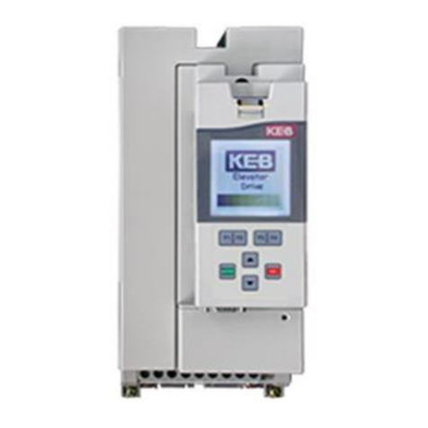
The KEB drive is an induction AC drive.
Figure 1: KEB Induction Drive
Equipment/Settings Verification
Set and verify the equipment matches the job specific parameters for proper operation. See C4
Controller sheet 01 Getting Started Parameter Table for more information.
Figure 2: Example of Parameter Table
Scroll through the motor parameters and verify that they are set to the motor nameplate
values prior to performing the Motor Learn procedure.

Drive Startup Manual KEB-Induction
Page 2 © 2020 Smartrise Engineering, Inc. All Rights Reserved March 5, 2020
Grounding Requirements
NOTE: A proper and effective building ground connection is required for the safe and successful
operation of the controller.
Examples of a proper building-to-controller ground is as follows:
Attach the ground wire to the street side of a water main.
Attach the ground wire to a grounding rod in the pit.
The controller has a common ground bus terminal connection.
Figure 3: Ground Bus Terminal
The building, motor, transformer, and filter(s) must all share a common ground. This
removes ground loops, limits impedance, and routes noise into the ground.

Drive Startup Manual KEB-Induction
March 5, 2020 ©2020 Smartrise Engineering, Inc. All Rights Reserved Page 3
Wiring
A checklist must be completed during the drive wiring process. See Appendix 1 for terminal
location.
Power
Perform the following to connect power. See C4 Controller sheet 03 Machine Room for job
specific information.
Connect main line power to terminal blocks L1/L2/L3.
Connect the ground wire to the yellow/green terminal block next to L1-L3.
Brake
Perform the following to connect the brakes. See C4 Controller sheet 05 Brakes for job specific
information.
Connect the main brake wiring to terminal K1 / K2 and the secondary brake wiring (if
equipped) to terminals J1 / J2 located on the terminal block next to the M Contactor.
Motor / Encoder
Perform the following to connect the drive to the motor and encoder cable. See C4 Controller
sheet 4 Motor and Drive Connections for job specific information.
Connect motor leads to the M contactor at T1/T2/T3.
Connect the encoder cable to the encoder cable mounted on the drive.
The table below lists the Wiring References for Common Encoders.
Table 1: Wiring References for Common Encoders
Encoder Imperial / PG-X3 Magil IH740 / IH950 Accucoder Wachendorff
Industrial
Encoder
(Canada)
PWR Red (2) Red (2) Brown (2) Brown Brown Brown
COM Black (1) Black (1) White (1) Blue White
(Shield)
White
A
White (3)
White (3)
Green (3)
White
Green
Green
/A
Black/White
(6)
Brown (6)
Pink (6)
Green
Red
Pink
B
Blue (4)
Green (4)
Yellow (4)
Yellow
Yellow
Yellow
/B
Red/Black (7)
Blue (7)
Blue (7)
Gray
Black
Blue
Z
Orange (5)
Yellow (5)
Gray (5)
Gray
Gray
/Z
Green (8)
Orange (8)
Red (8)
Violet
Red
DAT

Drive Startup Manual KEB-Induction
Page 4 © 2020 Smartrise Engineering, Inc. All Rights Reserved March 5, 2020
Encoder Imperial / PG-X3 Magil IH740 / IH950 Accucoder Wachendorff
Industrial
Encoder
(Canada)
/DAT
CLK
/CLK
SHIELD
Shield
Shield
Shield
Shield
Shield
Shield
Construction
All safety inputs are functional during Construction mode on the C4 product. When these safety
devices are installed, they are connected per C4 Controller sheet 02 Machine Room I/O of the
prints, even if still on Construction mode. The following includes instructions for when none of
these devices have been installed prior to beginning on Construction mode.
Perform the following to wire the Construction Box. See C4 Controller sheet 01 Getting Started
for job specific information.
Connect a jumper from L120 to terminals LFT, LFM, and LFB.
a. If rear doors are used, connect LRT, LRM, and LRB.
Connect a jumper from H120 to PIT, BUF, BFL, and TFL.
If secondary brake is present, connect M120 to SFM.
Connect H120 through your machine room Run/Stop switch and connect it to SFH. A
closed switch indicates run; an open switch indicates stop. If no Run/Stop switch is being
used, connect H120 to SFH.
Connect your run bug. Wire the Up button to input CUP and the Down to input CDN.
Wire the Enable to CEN, jump high if not available.
a. If no run bug is being used, leave the inputs unwired.
Enable Run box by setting the option in Setup |Miscellaneous | Enable Const. Box to
ON.
NOTE: When this option is ON, the onboard inspection buttons are disabled.
Connect a jumper from 24VDC to MM.
Verify the Car Door Bypass and Hoistway Bypass switches are in the OFF position.
Place the Inspection switch to INSPECTION.

Drive Startup Manual KEB-Induction
March 5, 2020 ©2020 Smartrise Engineering, Inc. All Rights Reserved Page 5
Figure 4: Example of Construction Wiring

Drive Startup Manual KEB-Induction
Page 6 © 2020 Smartrise Engineering, Inc. All Rights Reserved March 5, 2020
Powering Up
Perform the following to power up the drive.
Apply external power by closing the main disconnect.
Close the two-pole breaker and all pushbutton breakers.
Verify the LCD on the Smartrise board and the Magnetek Drive powers up.
Figure 5: Breakers
KEB Motor Learn
Smartrise programs the KEB drive with factory defaults to properly communicate with the
controller. After factory testing, customer motor data (from customer’s EDF) is programmed
into the drive to provide an easier “out of box” installation.
Initial Setup
The complete motor data must be learned with the automated learn function.
The Motor Learn function can be found under the Tune Parameters group from the
Programming menu (Home > Prog > Tune Parameters > LL01).
Perform the following for initial setup.
Set Motor Tuning LL01 to Start.
Follow the instructions on the LCD screen.
•On the MR board, Toggle DIP 6A (Top bank) to on to start the tune process
•Once complete, turn off DIP 6A.

Drive Startup Manual KEB-Induction
March 5, 2020 ©2020 Smartrise Engineering, Inc. All Rights Reserved Page 7
The process should take 2-5 minutes and will emit a high-pitched noise while the drive
measures various motor parameters.
Encoder Synchronization
The Encoder Synchronization process determines the correct A/B encoder channel phasing and
direction of rotation for Induction motors.
Perform the following for encoder synchronization.
Set Encoder Synchronization LL07 to Start.
Follow the directions on the drive keypad.
NOTE: The drive runs the elevator and swaps the phasing and direction of the A/B
channels as needed.
Operation
Run the car and complete the checklist during the verification process.
No Faults
Make sure the car is moving without triggering a fault either on the Smartrise SRU Board or the
drive. If the SRU Board displays a drive fault, look at the drive to see what the fault is. See Drive
Fault / Encoder Fault for troubleshooting drive fault.
Proper Direction
Make sure the car is moving in the same direction as the control switch on the Run Bug. See
Wrong Direction for troubleshooting proper direction faults.
At Speed
Make sure the car is moving at the proper inspection speed (approximately 50 fpm). See Car
Moving to Slow or Rough for troubleshooting at speed faults.
Under Control
Make sure that the car is moving under full control. The car should stop when commanded
from the Run Bug. Verify that the car runs with no faults for 10 seconds or more. See Brake Not
Lifting for troubleshooting under control faults.

Drive Startup Manual KEB-Induction
Page 8 © 2020 Smartrise Engineering, Inc. All Rights Reserved March 5, 2020
Troubleshooting
The following sections list troubleshooting procedures. See Appendix 3 for advanced
troubleshooting procedures.
Drive Fault / Encoder Fault
The most common fault at drive startup is the Encoder fault.
Perform the following checks to correct this fault:
Check for a solid shield-to-ground connection at the motor and drive.
Check for correct colored encoder wires to the terminals.
Swap wires A with A/ or swap A and A/ with B and B/.
Perform the Encoder Synchronization process after swapping any encoder wires. See
Encoder Synchronization.
Brake Not Lifting
If the brake is not picking, make sure that the brake is wired according to C4 Controller sheet 05
Brake Connection and if there is a second brake installed, verify that the EB terminal is
jumpered to the terminal. See the C4 Controller sheet 01 – Getting Started for more
information.
If the brake has the proper voltage check the following:
During a run command, check the DC voltage between points K1 / K2 and J1 / J2 if
secondary brake is installed. Verify the voltages are also at the brake coil(s) when
commanded to pick.
Verify that the actual brake voltage matches the brake coil voltage shown on the C4
Controller sheet 01 – Getting Started Parameter table.
Wrong Direction
If the car is moving in the wrong direction check the following:
On the Smartrise controller board make sure that IO CUP comes on when commanding
the UP direction and IO CDN comes on when commanding the DOWN direction.
Swap two of the motor leads (T1 with T2).
Car Moving to Slow or Rough
If the car is moving to slow or rough perform the following:
Swap encoder wires A+ and A- on drive.
Verify the brakes are lifting fully.

Drive Startup Manual KEB-Induction
March 5, 2020 ©2020 Smartrise Engineering, Inc. All Rights Reserved Page 9
Appendix 1 Terminal and Encoder Card Locations
The figure below shows the terminal and Encoder card locations.
Figure 6: Terminal Connections

Drive Startup Manual KEB-Induction
Page 10 © 2020 Smartrise Engineering, Inc. All Rights Reserved March 5, 2020
Figure 7: Encoder Card Location

Drive Startup Manual KEB-Induction
March 5, 2020 ©2020 Smartrise Engineering, Inc. All Rights Reserved Page 11
Appendix 2 KEB Programming Menu
The programming menu is where all manual parameter adjustments are made and can be
accessed at Home > Prog (F3).
The table below lists the Parameter Groups.
Table 2: Parameter Groups
Parameter Parameter Group Description
OS00 - OS22
Operator System
Provides general information about the operator and
drive hardware and software. Additionally, the
operator password level is set here which allows for
different access levels.
US02 - US06
Basic Setup
Provides the very basic information needed to
configure the drive, including motor type, control
type, and contract speed.
LI01 - LI20
Inputs:
Defines the logic of the inputs and assigns control
functionality to the digital inputs.
LM01 - LM33
Motor Data
Defines and displays all relevant motor values and
motor protection settings.
LE01 - LE36
Encoder Data
Defines the settings and scalings of the drive
encoders.
LN01 - LN05
Machine Data
Defines the machine data, including sheave diameter,
roping ratio, and rated load values.
LS01 - LS55
Speed Profile
Adjusts the speed, acceleration, and jerk values
across the elevator run profile.
LL01 - LL17
Tune Parameters
Contains the automatic tuning parameters. Here you
can program the system inertia, motor data, and
motor pole positions.
LC01 - LC44 Control Setting
Contains advanced adjustment parameters which
affects the motor gains, system inertia gains, pre-
torque, etc.
LT01 - LT13
Timer Parameters
Adjusts brake and drive signalling timers.
LP01 - LP08
Positioning Parameters
Contains the adjustments needed for the drive.
LX01 - LX18
Special Functions
Allows advanced adjustment of the drive and
facilitates function tests of drive components.
CH01 - CH03 Configuration Handling
Allows a user to save parameters and default to OEM
settings.
LA01 - LA40
Analog I/O
Defines and adjusts the analog inputs and outputs.
LO01 - LO20
Outputs
Defines the functionality of the relay and solid-state
drive outputs.

Drive Startup Manual KEB-Induction
Page 12 © 2020 Smartrise Engineering, Inc. All Rights Reserved March 5, 2020
Appendix 3 Advanced Troubleshooting
The following list of troubleshooting steps are to help with the startup and smooth operation of
the drive.
Starting Over (Defaulting Drive)
Sometimes parameters get changed, or certain functions that should work are not working for
no apparent reason. In this case, starting over with factory defaults may solve these issues.
Perform the following to default the drive to factory settings.
Navigate to US03 and load the opposite configuration of what is shown.
To load opposite configuration:
a. If the original configuration is Gearless, navigate to PM | Induction |Gearless and
load (Induction) Geared and Save. Go to step 3.
b. If the original configuration is Geared, navigate to PM | Induction |Geared and load
(Induction) Gearless and Save. Go to step 4.
After this value is saved, go back and load the original configuration as Gearless. This
does a complete background default on the drive. Go to step 5.
After this value is saved, go back and load the original configuration as Geared. This
does a complete background default on the drive.
Navigate to US05 and select Write Configuration to Drive.
Perform the following to re-load OEM values (Programmed by Smartrise).
Go to US05 and select Restore OEM Defaults to reload Smartrise settings.
Vibration
If any vibration occurs:
Cut the KP (LC03, LC04) and KI (LC08, LC09) gains in half.
Motor Noise
If the motor sounds noisy:
Change LE.05 to 8 (PM)
Motor Not Running When Given Command
Perform the following when a motor is not running with given command.
Check LI.01: Needs to be NPN for the drive to receive signals from controller.
Verify parameters LF.41 through LF.43 are set to the correct value. See Parameter table
on the prints.
Other manuals for KEB-Induction
1
Table of contents
Other Smartrise DC Drive manuals

Smartrise
Smartrise KEB-Induction Installation and operation manual

Smartrise
Smartrise C4 Installation and operation manual

Smartrise
Smartrise KEB Series Installation and operation manual

Smartrise
Smartrise Magnetek L1000A Installation and operation manual

Smartrise
Smartrise Magnetek HPV900AF Installation and operation manual

Smartrise
Smartrise HPV900 Installation and operation manual

Smartrise
Smartrise C4 User manual

Smartrise
Smartrise HPV900-PM Installation and operation manual

Smartrise
Smartrise KEB-PM Installation and operation manual

Smartrise
Smartrise KEB-PM Installation and operation manual