Selec ATSEL FD300 User manual

High Performance
AC Drives
Selec Subsidiaries: www.selecusa.com | www.selec-europe.com | www.selecaustralia.comSelec USA: Selec GmbH: Selec Australia:
Selec Controls Pvt. Ltd.
EL-27-1, Electronic Zone, TTC Industrial Area, MIDC, Mahape, Navi Mumbai 400710, INDIA.
Tel.:+91-22-4141 8468 / 452. Fax: +91-22-41418 408. Email: [email protected] | www.selec.com

User Manual Preface
This manual provides you with relevant instructions and precautions
for installation, wiring, function parameter setting, routine maintenance,
troubleshooting and troubleshooting of the inverter.
In order to fully utilize the functions of the product and ensure the safety of
users and equipment, please read this manual carefully before using the
inverter. Improper use may cause the inverter to operate abnormally,
malfunction, reduce the service life, and even cause equipment damage,
personal injury and other accidents!
Please pay special attention to the following safety precautions when
handling this product.
•Please ensure to turn off the power when wiring.
•The AC power cord must never be connected to the inverter output
terminals U, V, W.
•The inverter must be properly grounded.
•There is a high voltage circuit inside the inverter. It is strictly forbidden
to touch the internal parts by hand.
•Only qualified electricians can install, wire, repair and repair the
inverter.
•Install the inverter in a suitable environment to prevent direct exposure
to high temperatures and sunlight, and to avoid splashing of moisture
and water droplets.
•Please perform at least five minutes after the power is turned off
during inspection and maintenance.
•Never modify the parts or circuits inside the inverter by yourself.
•Do not test the voltage inside the inverter.
•This series of products cannot be used in situations that endanger
personal safety.
PREFACE

User ManualUser Manual
1-1 Inspection
Each inverter is subjected to strict quality control before being
shipped from the factory, and is made of enhanced anti-collision packaging.
After the customer unpacks, please check the following items:
1-2 Illustrations for nameplate of FD300
Chapter 1
PRODUCT INFORMATIONCONTENTS
Contents
1
8. Inspection and maintenance
8-1 Maintenance
8-2 Inspection and replacement of consumable parts
8-3 Storage
8-4 Inverter warranty
9. Appendix
Appendix A Modbus communications
Appendix B Brake resistor selection
Appendix C Appearance dimensions and installation dimensions
4. Keypad operation
4-1 Description of the keyboard panel
4-2 Function code modification, view instructions
7. Faults and Solutions
7-1 Fault alarm and Solutions
7-2 Common faults and solution
6. Parameter Instruction
P0 Basic function
P1 First motor parameter
P2 Vector control parameter
P3 V/F control parameter
P4 Input terminal
P5 Output terminal
P6 Start and stop control
P7 Keyboard and display
P8 Accessibility
P9 Failure and protection
PA Process control PID function
PB Swing frequency, fixed length and counting
PC Multi-segment instruction and simple PLC function
PP User password
A0 Torque Control Function
A5 Control optimization parameter
A6 Group AI curve setting
AC AIAO Correction
1. Production information
1-1 I nspection
1-2 Name plate
1-3 Specification of inverter
2. Installation
2-1 Installation environment
2-2 Installation method and space
3. Wiring
3-1 Peripheral device connection
3-2 Standard wiring diagram
3-3 Main circuit terminal description
5. Function parameter
5-1 Basic function parameter
5-2 Monitoring parameter
•Check the package for instructions (with certificate and warranty card).
•Check the inverter nameplate and confirm that it is the product model
you ordered.
•If you ordered any option for the drive, please check to confirm.
•Check if the inverter is damaged during transportation.
MODEL : FD300–3–100-C-CE
POWER : 10HP/7.5KW
INPUT : 10PH 415V ±15% 50/60Hz
OUTPUT : 0–400Hz 17 A
019059037
HIGH POWERED INVERTER
Selec Control Pvt. Ltd
BAR CODE
Product Model
Power
Output Power Specification
Input Power Specification
Item Number
Illustrations for product model of FD300
MODEL : FD300 - 3 - 100 - C- CE
Product Series 3 Phase 10.0HP
RS485
Certification

User ManualUser Manual
Chapter 1 Chapter 1
3
2
Rated
Power kW
Output
current A
45
Rated
voltage V Three-phase 415V
1-3 Name plate
Rated
Power kW
Output
current A
Rated
voltage V Three-phase 415V
Vector control: 0~3200Hz V/F control:0~500Hz
0.5kHz~16kHz (The carrier frequency is
automatically adjusted based on the load features.)
Digital setting: 0.01 Hz
Analog setting: maximum frequency x 0.025%
Standard
functions
Maximum
frequency
Input frequency
resolution
Carrier frequency
Specification
Item
Sensor-less flux vector control (SFVC)
Closed-loop vector control (CLVC) (+PG Card)
Voltage/Frequency (V/F) control
Control mode
0.5Hz/150% (SVC); 0Hz/180%(FVC)
Startup torque
Speed stability
accuracy
1 : 100 (SVC)
Speed range 1 : 1000 (FVC)
±0.5% (SVC) ±0.02% (FVC)
Torque control
accuracy ±5% (FVC)
G type: 60s for 150% of the rated current,
3s for 180% of the rated current
P type: 60s for 120% of the rated current,
3s for 150% of the rated current
Overload capacity
Torque boost Auto boost;
Manual boost: 0.1%~30.0%
Standard
functions
Specification
Item
V/F curve
Straight-line V/F curve
Multi-point V/F curve
N-power V/F curve (1.2-power, 1.4-power,
1.6-power, 1.8-power, square)
V/F separation 2 types: complete separation; half separation
Acc./dec. curve
Straight-line ramp
S-curve ramp
Four groups of acceleration/deceleration time
with the range of 0.00s~65000s
DC braking
DC braking frequency: 0.00 Hz ~ max. frequency
Braking time: 0.0~100.0s
Braking trigger current value: 0.0%~100.0%
JOG control
JOG frequency range: 0.00Hz~50.00 Hz
JOG acceleration/deceleration time: 0.00s~65000s
Built-in PLC,
multiple speeds
It realizes up to 16 speeds via the simple
PLC function or combination of DI terminal states
Built-in PID It realizes closed loop control system easily.
Auto voltage
regulation (AVR)
It can keep constant output voltage automatically
when the mains voltage fluctuation.
Over voltage/Over
current stall
control
The current and voltage are limited automatically
during the running process so as to avoid
frequently tripping due to over voltage/over current.
Rapid current
limit function
It can auto limit running current of frequency
inverter to avoid frequently tripping.
Torque limit and
control
(Excavator characteristics) It can limit the torque
automatically and prevent frequently over current
tripping during the running process.
Torque control can be implemented
in the VC mode.
Indivi-
dualized
functions
High performance
Control of asynchronous motor is implemented
through the high-performance current vector
control technology.
Instant power
off not stop
The load feedback energy compensates the
voltage reduction so that the frequency inverter
can continue to run for a short time.
Rapid current limit To avoid frequently over current faults of the
frequency inverter.
9 13 17 25 32 38 45 60 75 90
55 75 90 110 132 147
110 150 176 210 250 300
3.7 5.5 7.5 11 15 18.5 22 30 37

Specification
Item
Indivi-
dualized
functions
User ManualUser Manual
Chapter 1 Chapter 1
5
4
Virtual IO Five sets of virtual input and output for simple
logic control
Timing control Time range: 0.0~6500.0 minutes
Multi-motor
switching
Four sets of motor parameters for four motor
switching control
Multiple
communication
protocols
Currently supports communication bus via
Modbus-RTU and later will support
PROFIBUS-DP, CAN open, etc.
Motor overheat
protection
The optional I/O extension card enables AI3 to
receive the motor temperature sensor input
(PT100, PT1000) so as to realize motor overheat
protection.
Multiple encoder
types
It supports incremental encoder and encoders such
as differential encoder, open-collector encoder,
resolver, UVW encoder, and SIN/ COS encoder.
Running
command
giving
key panel
Control terminals
Serial communication port
You can switch between these giving in various ways.
Frequency giving
There are 10 kinds frequency giving: digital
setting, analog voltage setting, analog current
setting, pulse setting, serial communication port
setting, panel potentiometer, etc.
You can switch between these giving in various ways.
Run
Auxiliary
frequency
giving
There are 10 kinds auxiliary frequency giving.
It can implement tiny tuning of auxiliary
frequency and frequency synthesis.
Input terminal
Standard:
5 digital input (DI) terminals, one of which
supports up to 100 kHz high-speed pulse input
2 analog input (AI) terminals, support 0V~10 V
voltage input or 0 mA~20 mA current input
Expanding capacity:
5 DI terminals
1 AI terminal supports -10V~+10 V voltage input.
Output terminal
Standard
1 high-speed pulse output terminal (open-collector)
that supports 0–100 kHz square wave signal output
1 digital output (DO) terminal
1 relay output terminal
2 analog output (AO) terminals,
support 0 mA~20 mA current output or
0 V~10 V voltage output.
Expanding capacity:
1 DO terminals
1 relay output terminals
Display
LED display It displays the parameters.
Parameters copy It can implement copy parameters function by
PC software.
Key locking and
function selection
It can lock the keys partially or completely and
define the function range of some keys so as to
prevent disoperation.
Protection mode
Motor short-circuit detection at power-on,
input/output phase loss protection, overcurrent
protection, overvoltage protection, under-voltage
protection, overheat protection and overload
protection, etc.
Altitude Lower than 1000 m
Ambient
temperature
-10°C~ +50°C (If the ambient temperature is
between 40°C and 50°C, the power grade is
reduced for use)
Humidity Less than 95%RH, without condensing
Vibration 2
Less than 5.9 m/s (0.6 g)
Storage temperature
-20°C ~ +60°C
Run
Specification
Item
Indoor, no direct sunlight, dust, corrosive gas,
combustible gas, oil smoke, vapor, drip or salt.
Enviro-
nment
Installation
location

INSTALLATION
2-1 Installation environment
•Locations free of water droplets, vapors, dust and oily dust.
•Non-corrosive, flammable gas and liquid.
•No floating dust metal particles.
•The environment temperature is -10°C ~ 50°C. If the environment
temperature exceeds 40°C, please place it in a well ventilated place
and delete the inverter
•Strong and vibration-free place.
•Locations without electromagnetic noise interference.
2-2 Installation method and space
•The inverter should be installed on a structure that does not burn, such
as metal, otherwise a fire accident may occur.
•The inverter should be installed vertically and securely with screws. Do
not flip, tilt or install horizontally. When the inverter runs, heat is
generated. To ensure the passage of the cooling air, a certain space is
left during installation (as shown in the figure).
•When installing the inverter in the control cabinet, consider ventilation
and heat dissipation to ensure that the ambient temperature of the
inverter does not exceed the specified value. Do not install the inverter
in a closed box with poor ventilation.
•When installing multiple inverters in the same control cabinet, it is
recommended to install them side by side in order to reduce the
thermal impact between each other. If it is necessary to install up and
down, a partition plate must be provided to reduce the influence of heat
generated in the lower part on the upper part (as shown in the figure).
•Do not allow foreign matter such as various fibers, paper sheets, chips
(chips) or metal fragments to enter the inverter.
50mm 50mm
≥100mm
≥100mm
UP
Right
CONVERTER
CONVERTER
CONVERTER
User ManualUser Manual
Chapter 2 Chapter 3
7
6
Installation size
Power level
≤15kw
18.5~30kw
≥37kw ≥50mm ≥300mm
≥50mm ≥200mm
≥20mm ≥100mm
A B
WIRING
In order to ensure the safety of operators and inverters, it is
necessary to be operated by qualified professional electricians. The
following are special considerations when wiring :
3-1 Peripheral device connection
•Make sure the input power is off before wiring.
•The ground terminal of the inverter must be reliably grounded.
•Verify that the rated voltage of the inverter matches the AC power
supply voltage.
•The power cable must be connected to the R, S, and T terminals of the
inverter. The motor cable should be connected to the U, V, and W
terminals. Do not connect the fault. Otherwise, the inverter will be
damaged internally.
•Confirm that the terminals and wires are reliably connected, and the
screws of the main circuit terminals are secured.
•Do not touch the main circuit terminals, otherwise there is danger of
electric shock.
Breaker AC reactor Electromagnetic
contactor Noise Filter Braking Unit Noise Filter
Name
Select the
appropriate
model, the
rated current
is not less than
1.5 times the
rated current
of the inverter
Used to
improve
input power
factor
Instruction
Configuration
Three-phase
power
Braking
unit
(+) (-)
R U
SV
T W
M
Used to
control power
on and off
Used to
reduce the
radio
interference
generated
by the
inverter
It is optional when
the braking torque
can’t meet the
requirements
of use. It is
suitable for large
inertia load and f
frequent start and
stop.
It is used to
reduce the
radio
interference
on the output
side of the
inverter.
MC
Braking unit AC output reactor
Braking resistor
Motor
Use within the allowable power supply
specification of the AC drive
Select a proper breaker to resist large
in-rush current that flows into the AC drive
at power-on.
To guarantee safety, use an electromagnetic
contactor. Do not use it to start or stop
the AC drive because such operation reduces
the service life of the AC drive.
Suppress the high order harmonic to improve
the power factor.
Three-phase AC
power supply
Moulded case circuit
breaker (MCCB) or earth
leakage circuit breaker
(ELCB)
Electromagnetic
contactor
AC input
react or
Noise filter on
input side
Reduce the
electromagnetic
interference on
the input side
Reliably ground the motor and
the AC drive to prevent electric
shock.

User ManualUser Manual
Chapter 3 Chapter 3
3-2-1 Standard wiring diagram for FD300
9
8
Braking resistor
QF MC
R/L1
S/L2
T/L3 T
S
R
B1 B2
U
W
V
PE
M
FWD
External fault
REV
Multi-phase
reference velocity 1
Common terminal
X1 Input terminal 1
X2 Input terminal 2
X3 Input terminal 3
X4 Input terminal 4
COM
PE
COM
X5 Input terminal 5
CN1
0-10V Input
0-20VmA Input
Potentio-
meter
3-5K
+10V Frequency setting
power supply
AI1 Multi-functional
Analog input
AI2 Jumper 3
GND
PE
0-20mA
AI2
0-10V
Jumper 4
0-20mA
AO
0-10V
AO
GND
Analog output
Default setting:
operating frequency
0-10V/0-20mA
15V
485+
485-
GND
485 communication
+24V
port
Y1
8
Default setting:
Run command
ROA
ROB
ROC
Default setting:
Fault output
Output of relay
FD100
BR
RY1
3 phase power supply
Single phase 220V inverter
input connect with L N
415V±15%, 50/60Hz
Frequency given
0-10V
MC
R/L
S/N
T
R
S
T
X1
X2
X3
X4
X5
COM
PE
+10V
AI1
AI2
GND
PE
Input 0-20mA
Input 0-10V
W
V
U
PE
QF
B1 B2
AO out
RY1
ROA
ROB
ROC
M
J3
0-10V
AI2
0-20mA
+24V
Y1
J5
Default setting
Three-wire control
mode
3-5K
AO
GND
PE
Motor
grounding
Grounding of
power measurement
J4
0-10V
AO
0-20mA
COM
Main
circuit
Control circuit
1
3
5
7
485+
485-
FWD
REV
Multi-phase
reference velocity 1
Multi-phase
reference velocity 2
Input terminal 1
Input terminal 2
Input terminal 3
Input terminal 4
Default setting:
operating frequency
0-10V / 0-20mA
Default setting:
Run indication
Output of relay
Current is less than 30mA
Output of relay
Default setting:
Fault output
Potentiometer
Preset frequency
0-10V
Power for
frequency
setting
Multi-functional AI
Three-phase source 415V ±15%
Single-phase source 220V ±15%
50/60Hz
3-3 Main circuit terminal description
Terminal
symbol (code) Functional descriptions
Power input terminal for three-phase 380V inverter.
(Power input terminal for single-phase 220V inverter)
The inverter output terminal is connected to a 3phase AC motor.
Braking resistor connection terminal (optional)
External brake unit connection terminal (optional).
Ground terminal.
R, S, T
L,N
U, V, W
B1, B2
(+), (-)
When wiring, please follow the electrical regulations to ensure the safety.
3-3-1 Power input terminal R, S,T
ŸIn order to prevent the high voltage and high current input into the power
supply circuit and damage the rectifier part, it is necessary to connect the
AC reactor on the input side, and also improve the power factor of the
input side.
ŸDo not use the main circuit power ON/OFF method to control the
operation and stop of the inverter. The drive's operation and stop should
be controlled using the RUN and STOP keys on the keypad panel or the
control loop terminals. If the main power ON/OFF method must be used
to control the operation of the inverter, it can only be performed once per
hour.
ŸA circuit breaker is required between the three-phase AC input power
supply and the main circuit terminals (R, S and T). It is better to connect a
magnetic contactor (MC) in series to cut off the power supply when the
inverter protection function is activated (the R-C surge absorber is
required at both ends of the electromagnetic contactor).
ŸTo reduce the interference of the inverter to surrounding equipment, the
noise filter can be connected to the input side.
ŸIf the inverter is equipped with an earth leakage circuit breaker as a
leakage fault protection, in order to prevent the leakage circuit breaker
from malfunctioning, please select a sensitivity current of 200 mA or
more and an operation time of 0.1 second or longer.
ŸDo not connect the three-phase power supply to the single-phase power
supply.
Braking
unit
BR
BR
Three-phase source 380V±15%
50/60Hz
Single-phase source 220V±15%
R/L
S/N
T
QF MC
R
S
T
(+)/B1 B2 (-)
U
V
W
PE PE
Main Circuit M
Motor
grounding
Grounding of power
measurement
FWD
REV
Non-function
Default setting
X1
X2
X3
X4
X6
X5
COM
PE
AO
GND
+24V
Y1
COM
Y2
COM
ROA
Input terminal 1
Input terminal 2
Input terminal 3
Input terminal 4
Input terminal 6
Input terminal 5
AO out
RY1
RY2
Default setting :
Operating
frequency
0-10V / 0-20mA
Default setting :
Run indication
Default setting :
Direction
indication
Output of relay
Current is less than 30mA
Output of relay
Default setting :
Fault output
Non-function
Non-function
Non-function
ROB
ROC
Preset frequency
0-10V
Potentiometer
3-5K
Input 0-10V
Input 0-20mA
+10V
AI1
AI2
GND
PE
Control Circuit
Power for
frequency
setting
Multi-functional AI
J13
0-20mA
AO
0-10V
J1
0-20mA
AI2 J2
0-10V

User Manual Chapter 3
MC
R/L1
S/L2
T/L3
R
S
T
X1
X2
X3
X4
X5
X6
COM
Input terminal 1
+10V
AI1
AI2
GND
PE
Frequency given
0-10V
0-20mA Input
0-10V Input J4 jumper
Frequency setting
power supply
Multi-function
analog inout
W
V
U
PE
QF (+)/B1 B2 (-)
Braking unit
BR
Analog output 0-10V/0-20mA
RY1
ROA
ROB
ROC
Relay output
RY2
M
Breaker pull-in,
current less than 30A
0-10V
AI2
0-20mA
J5 jumper
0-10V
AO
0-20mA
+24V
Y1
Y2
BR
External keyboard port
J13
FWD
REV
External fault
Multi-pase reference
velocity 1
Default:Running
frequency
Default:
running
indication
Default:
Direction
indication
(Default: Fault output)
Potentio-
meter
3-5K
Common terminal
AO
GND
485+
485-
GND
RS485 communication
Braking resistor
Input terminal 2
Input terminal 3
Input terminal 4
Input terminal 5
Input terminal 6
Multi-pase reference
velocity 2
Multi-pase reference
velocity 3
Default
settings
3 phase power supply
Single phase 220V inverter
input connect with L N
415V±15%, 50/60Hz
PE
User Manual
Chapter 3
11
10
3-3-2 Connection of inverter output terminals U, V, W
ŸThe inverter output terminals are connected to the 3-phase motor in the
correct phase sequence. If the motor rotates in the wrong direction, the
wiring of any two phases of U, V, and W can be exchanged.
ŸThe output side of the inverter cannot be connected to the capacitor and
the surge absorber.
ŸWhen the wiring between the inverter and the motor exceeds 50 meters,
the distributed capacitance between the lines will generate a large
leakage current, which may cause the inverter to over-current trip. At the
same time, in order to avoid damage to the motor insulation, the output
reactor must be compensated. .
ŸIf the installation location of the inverter is quite sensitive to interference,
please install an output noise filter to reduce the carrier frequency of the
inverter and reduce interference.
3-3-3 Braking resistor and brake unit connection
ŸWhen the load inertia is large and it is necessary to stop frequently or stop
for a short time, when the braking capacity of the inverter is insufficient or
to increase the braking torque, etc., the braking resistor or the braking
unit may be selected as needed.
ŸWhen the inverter has no built-in braking unit, the main circuit (+) and (-)
terminals are connected to the external braking unit.
ŸDo not connect the main circuit (+) and (-) terminals to the braking
resistor.
ŸThe main circuit B1, B2 terminal is connected to the braking resistor
(there is B1, B2 terminal indicates that the inverter has built-in braking
unit).
3-3-4 Inverter Grounding Terminal PE
ŸFor safety and noise reduction, the ground terminal PE of the inverter
must be well grounded.
ŸUse the specified standard grounding wire and be as short and thick as
possible (grounding impedance 10Ω or less).
ŸThe grounding wire of the inverter must not be grounded together with
large current loads such as electric welders and high-power motors, but
must be grounded separately.
ŸThe power supply line generally adopts 5 core wires, of which 3 are fire
wires, 1 neutral wire, and 1 ground wire. It is strictly forbidden to use the
neutral wire as ground wire.
ŸWhen multiple inverters are installed together, all inverters must be
directly connected to the common ground.
(a) correct (b) not recommend (c) error
3-4 Control circuit terminal description
Terminal description &
default setting
Classification Mark Terminal name
Multi-functional
input
X1
X2
X3
X4
X6
COM
Multi-functional input
terminal 1 Default setting : Forward
Multi-functional input
terminal 2 Default setting : Reverse
Multi-functional input
terminal 3 Default setting : No function
Multi-functional input
terminal 4 Default setting : No function
Multi-functional input
terminal 6
Default setting : No function
can be used as a high
speed pulse input
Public terminal
Multi-functional input common
+24V power supply
reference groung
CN1
Needle base
COM
X5
RS485
485- 485+
8 7 6 543 21
6 543
Please refer to the following illustration:
+24V Y1 Y2 X1 X2 X3 X4 AO 485- 485+
ROA ROB ROC COM X5 X6 GND AI1 AI2 +10V
X5 Multi-functional input
terminal 5 Default setting : No function

PRG FUNC
ESC
JOG
REV
STOP
RESET
RUN
Hz V
A
RPM %
L/R F/R
RUN
-
+
Positive and negative
indicator
light on: reverse
light off: forward
Multi-function
selection button
Stop/reset button
Display information
and return button
Running
Increment button
Decrement button
Command source
Light on: terminal control
Light off: key pad control
Running indicator
Potentiometer
Shift button
Programming
button
Current
indication
Unit indicator
Voltage
indication
Unit indicator
Running indicator
Command source indicator
Light on: terminal control
Light off: key pad control
Blinking: communication control
Potentiometer
Programming button
Running
Tuning/torque control fault
indicator
Positive and negative indicator
Light on: reverse
Light off :forward
enter
Increment button
Shift button
Decrement button
Stop/reset button
Multi-function selection button
PRG FUNC
ESC
JOG
REV
STOP
RESET
RUN
Hz V
A
RPM %
L/R F/R
RUN
-
+
Positive and negative
indicator
light on: reverse
light off: forward
Multi-function
selection button
Stop/reset button
Display information
and return button
Running
Increment button
Decrement button
Command source
Light on: terminal control
Light off: key pad control
Running indicator
Potentiometer
Shift button
Programming
button
Current
indication
Unit indicator
Voltage
indication
User Manual Chapter 4
User Manual
Chapter 3
13
12
Terminal description &
default setting
Classification Mark Terminal name
AI1
AI2
+10V
Analog input
GND
Analog input 1 0~10V input
0~10V/0~20mA input
(J2 jumper is optional)
+10V DC 10mA
(potentiometer 3~5K)
Analog power
supply
Analog input-output reference
ground
Analog reference
ground
Multi-
functional
output
Y1
ROA
Default setting :
Inverter fault output
Relay output
ROA-ROB
(normally closed)
ROA-ROC
(normally opened)
ROB
ROC
Multi-functional output
terminal 1 Default setting : Running
Y2 Multi-functional output
terminal 2
Default setting : No output, can be
used as high speed pulse output
0~10V/0~20mA output (J1-
jumper is optional)
GND means ground
Analog output
Power supply
AO
+24V
Analog output terminal
+24V power +24V DC 100mA
COM power ground
Use a multi-core shielded cable or stranded wire to connect the
control terminals. When using a shielded cable (on one end of the drive), it
should be connected to the ground terminal PE of the drive. When wiring, the
control cable should be away from the main circuit and high-voltage lines
(including power lines, motor lines, relays, contactors, etc.) more than 20CM,
and avoid parallel placement. It is recommended to use vertical wiring to
prevent external interference from generating inverter errors action.
Analog input 2
485+ Standard RS-485 serial
communication interface
Please use twisted pair
or shielded wire
485 Positive signal
485-
Communi-
cation 485 Negative signal
KEYPAD OPERATION
4-1 Description of the keyboard panel
Keyboard panel
RUN When the light is off, the inverter is in the stop state. When the
light is on, the inverter is in the running state.
L/R
Keyboard operation, terminal operation and communication
operation indicator, the light off indicates the keyboard operation
control status, the light is on indicates the terminal operation
control status, and the light flashes to indicate that it is in the
communication operation control state.
F/R Positive and negative indicators, when the light is on, it indicates
that it is in reverse running mode.
Panel indicator description
TUNE
Tuning/torque control/fault indicator. When the light is on, it indicates
that it is in the torque control mode. When the light is flashing slowly,
it indicates that it is in the tuning state. If the light is flashing,
it indicates that it is in the fault state.
Hz
Lights indicate
frequency units
Lights up to indicate
current unit
The light is on to indicate
the voltage unit
A V
RMP The Hz lamp and the A lamp are simultaneously lit to indicate the
speed unit.
%The A and V lamps are lit at the same time to indicate the
percentage unit.
Positive and negative
indicator
light on: reverse
light off: forward
Multi-function
selection button
Stop/reset button
Display information
and return button
Increment button
Decrement button
Command source
Light on: terminal control
Light off: key pad control
Running indicator
Potentiometer
Date display
Voltage indication
Frequency indication
Current indication
Programming key
Shift key
RUN key
Running indicator
Potentiometer
Confirm key
Increment key
Multi-function key
Decrement key
Stop / Reset key
Command source
light on : terminal control
light off : Key pad control
light blinking : modus control
Positive & negative indicator
light off : forward
light on : reverse
User ManualUser Manual
Chapter 4 Chapter 4
3) Digital display area : A total of 5 LED displays, which can display the
set frequency, output frequency, various monitoring data and alarm codes,
etc.
Name
15
14
Positive and negative
indicator
light on: reverse
light off: forward
Multi-function
selection button
Stop/reset button
Display information
and return button
Running
Increment button
Decrement button
Command source
Light on: terminal control
Light off: key pad control
Running indicator
Potentiometer
Shift button
Programming
button
Current
indication
Unit indicator
Voltage
indication
Keyboard button description
Button Function
Programming
key Enter or exit menu level I.
Confirm key Enter the menu interfaces level by level,
and confirm the parameter setting.
Increasing
key Increase data or function code.
Decreasing
key Decrease data or function code.
Menu move
selection /
monitoring
key
Select the displayed parameters in turn in the stop or
running state, and select the digit to be modified
when modifying parameters.
Running key Start the frequency inverter in the operation panel
control mode.
Stop/Reset
key
Stop the operation when it is in the running state and
perform the reset operation when it is in the fault
state. The functions of this key are restricted by P7-02.
Multifunction
key
Perform function switch over (such as quick switch
over of command source or direction) according to
the setting of P7-01.
Potentio-
meter knob
Regulate the speed directly by panel potentiometer
when P0-03 is set to 4.
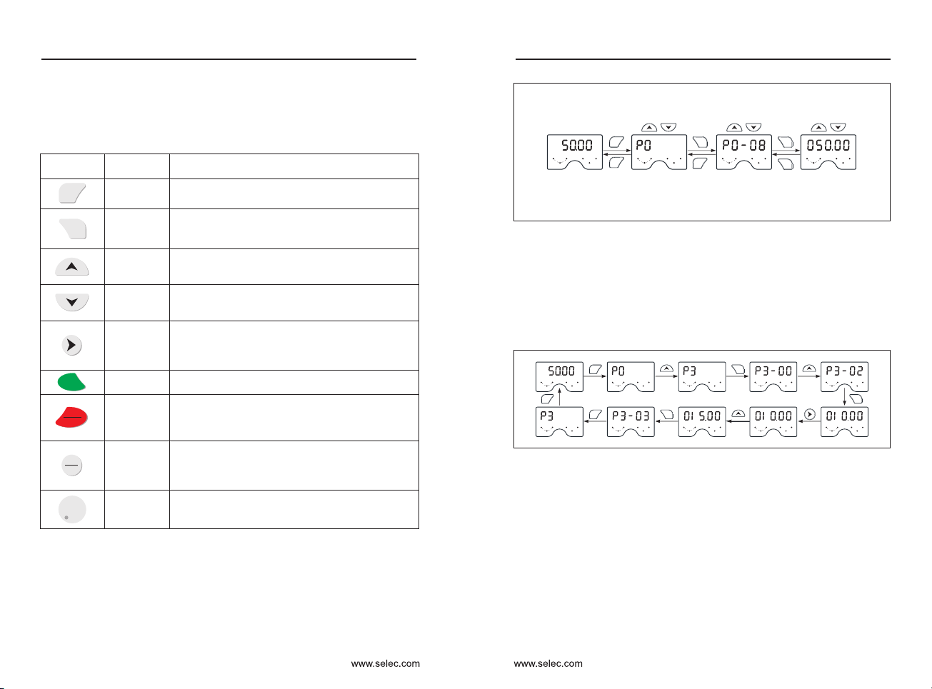
4-2 Function code modification, view instructions
Function code modification instructions
The operation panel of the inverter adopts a three-level menu structure for
parameter setting and other operations. The three levels of menu are:
function parameter group (first level menu) → function code
(second level menu) → function code setting value (third level menu).
The operation process is shown in Figure 4-2.
Status parameter
(default display)
Select the function
code group
Select the
function code
Set the value of
the function code
Level-I menu Level-II menu Level-III menu
Example: An example of changing the function code P3-02 from 10.00 Hz to
15.00 Hz. (black mark indicates flashing bit)
Note: When operating in a three-level menu, press the PRG or ENTER key to
return to the secondary menu. The difference between the two is: press the
ENTER key to save the set parameters and return to the second level menu,
and automatically transfer to the next function code; press the PRG key to
return directly to the second level menu, do not store the parameters, and
return to the current function code .
In the third level menu, if there is no flashing bit in the parameter, it means that
the function code cannot be modified. The possible reasons are as follows:
a) The function code is an unmodifiable parameter. Such as the actual
detection parameters, operating record parameters.
b) The function code cannot be modified in the running state, and can be
modified after it needs to be stopped.
How to view status parameters
In the stop or running state, the shift key can be used to switch between
displaying various status parameters. The function code P7-03 (operation
parameter 1), P7-04 (operation parameter 2), P7-05 (stop parameter) is
selected according to the binary bit to display whether the parameter is
displayed.
PRG
FUNC
ESC
JOG
REV
STOP
RESET
RUN
PRG
PRG
Hz V
A
RPM %
L/R F/R
RUN
Hz V
A
RPM %
L/R F/R
RUN PRG
Enter
Hz V
A
RPM %
L/R F/R
RUN
Hz V
A
RPM %
L/R F/R
RUN
Enter
Enter
50.00 050.00P0 P0-08
Change
parameter group
Change function
parameter selection
Change function
parameter value
PRG Enter Enter
Enter
PRG
PRG
PRG Menu
level1
Menu
level2
Menu
level3
Figure 4-2 Three-level menu operation flow Chart
PRG
Hz V
A
RPM %
L/R F/R
RUN
Hz V
A
RPM %
L/R F/R
RUN
Hz V
A
RPM %
L/R F/R
RUN
PRG
PRG
Hz V
A
RPM %
L/R F/R
RUN
Enter
Hz V
A
RPM %
L/R F/R
RUN
Hz V
A
RPM %
L/R F/R
RUN
Enter
Hz V
A
RPM %
L/R F/R
RUN
Hz V
A
RPM %
L/R F/R
RUN
Enter
Hz V
A
RPM %
L/R F/R
RUN
Hz V
A
RPM %
L/R F/R
RUN
ENTER

User Manual Chapter 4
User Manual
Chapter 4
17
16
FUNC
ESC
FUNC
ESC
FUNC
ESC
FUNC
ESC
PRG PRG PRG PRG
FUNC
ESC
PRG
FUNC
ESC PRG
Basic information
Main Menu
Secondary Menu
Date
Setting
Frequency
Operating
Frequency
Output
current Bar voltage Other
information
Data storage
and return
Basic information
Main Menu
Secondary Menu
Data
Setting frequency Operating frequency Output current Bar voltage Other information
FUNC
ESC
FUNC
ESC
FUNC
ESC
FUNC
ESC
FUNC
ESC
FUNC
ESC
FUNC
ESC
FUNC
ESC
PRG PRG PRG PRG
PRG
PRG
PRG
data storage and return
- - -
-+
-+
-+
-+
-+
-+
4-2 Illustrations of keyboard operation
FUNC
ESC
Other
information
FUNC
ESC
Bar voltage
FUNC
ESC
Output
current
Operating
frequency
FUNC
ESC
Setting
frequency
Basic information
PRG
PRG
FUNC
ESC
PRGPRG
FUNC
ESC
PRG
PRG
Main Menu
Secondary Menu
Data
P7-05=0000 0000 0011 0011B=33.
For example, in the stop state, P7-05 (stop parameter) is set to 33.
In the running state, P7-03 (operation parameter 1) is set to 7F.
The 7 status parameters of Bit00/Bit01/Bit03/Bit03/Bit04/Bit05/Bit06 are
selected: running frequency, set frequency, bus voltage, output voltage,
output current, output Power, output torque, key sequence switching to
display the selected parameters,
The four status parameters of Bit00/Bit01/Bit04/Bit05 are selected: set
frequency, bus voltage, AI1 voltage, AI2 voltage, and the key sequence
switches to display the selected parameter.
P7-05=0000 0000 0111 1111B=7F
After the inverter is powered off and then powered on, the displayed
parameters are defaulted to the parameters selected before the inverter is
powered down.
P7-03
LED
Running
display
parameters1
Bit12: Count value Bit13: Length value
Bit14: Load speed display Bit15: PID set up
Bit8: Output status Bit9: AI1 Voltage(V)
Bit10: AI2 Voltage (V) Bit11: AI3 Voltage(V)
0000~FFFF
Bit0: Operating frequency 1 (Hz)
Bit1: Setting frequency(Hz)
Bit2: bus voltage (V) Bit3: The output voltage(V)
Bit4: Output current(A) Bit5: Output Power(KW)
Bit6: Output current(%) Bit7: Input status
LED
Running
display
parameters2
LED Stop
display
parameter
P7-04
0000~FFFF
Bit4:Remaining running time
Bit6:AI2 Pre-correction voltage(V)
Bit0:PID Feedback
Bit7:AI3 Pre-correction voltage(V)
Bit10:Current running time(Min)
Bit2:Pulse input frequency(kHz )
Bit11:PULSE Input pulse frequency(Hz)
Bit1:PLC Stage
Bit9:Current power-on time(Hour)
Bit8:Line speed
Bit13:Encoder feedback speed(Hz)
Bit12:Communication setting
Bit14:Main frequency X display(Hz)
Bit15:Auxiliary frequency Y display(Hz)
Bit3:Operating frequency 2(Hz)
Bit5:AI1 Pre-correction voltage(V)
Bit10: Load speed Bit11: PID set
Bit08: Length value Bit09: PLC stage
Bit06: AI3 Voltage (V) Bit07: Count value
0000~FFFF
Bit12: PULSE Input pulse frequency (kHz)
Bit04: AI1 Voltage (V) Bit05: AI2 Voltage (V)
Bit00: Setting frequency (Hz) Bit01: bus voltage (V)
Bit02: X Input status Bit03: DO Output status
P7-05
User password setting
The inverter provides the user password protection function. When PP-00 is
set to non-zero, it is the user password. Exiting the function code editing
status password protection takes effect. Press PRG again, “-----” will be
displayed. Enter the user password correctly to enter the normal menu,
otherwise you will not be able to enter, so you must remember the password
after setting the user password.
To cancel the password protection function, only enter with a password and
set PP-00 to 0.

User Manual Chapter 5
5-1 Function parameters table
P0: Basic function parameters
Function
Code
Parameter
Name
Setting Range Default Proper-
ty
Modbus
Address
P0-00
GP type
1 : G (Constant torque
load model)
2 : P (Fan, pump type
load model)
1
P0-01
0 : Speed sensorless vector
control (SVC)
1 : Speed sensor vector
control (FVC)
2 : V/F control
0●
P0-02 0
P0-03
0 : Digital setting (non-retentive
at power failure)
1 : Digital setting (retentive at
power failure)
2 : AI1
3 : AI2
4 : panel potentiometer
5: Pulse setting (X6)
6 : Multi-segment instruction
7 : Simple PLC
8: PID
9 : Communication given
0
0 : Operation panel command
channel(LED close)
1 : Terminal command channel
(LED open)
2 : Communication command
channel(LED Flashing)
Converter must be switched off immediately by pushing the button
STOP/RESET if there is anything goes wrong with converter or motor; meanwhile,
please refer to Chapter 7 Fault Correcting to find out the reason why it
malfunctions. Even it is shut off, output terminals (U, V, W) may still cause electric
shock to anyone who touches them unless power ports (R, S, T) are disconnected
from main circuit.
Additionally, it will take some times for filter capacitor to discharge because
there is still charging voltage stored in the filter capacitor even main power source
is shut off. Charging indicator will be off if main power source is shut off; voltage in
the middle DC circuit must be tested by voltmeter. Only after it's confirmed that the
voltage is lower than specified value can internal circuit be touched.
5-2 Quick debugging
Start
Select preset
frequency (P0~01)
Select running &
control mode (P0~02)
Select Starting
mode (P2-00~04)
Select Acc-Dec time
(P0-04/P0-05)
Select running
direction (P0-06)
Select half mode
(P2-05~08)
Starting & Observing
Optimization of
parameters
P0-01
0 : Preset frequency
1 : Preset panel potentiometer
2 : Preset external Ai1
3 : Preset external Ai2
0 : Keyboard control
1 : Running by terminal,
effective control by STOP key
2 : Running by terminals,
ineffective control by STOP key
3 : Controlled by communication
0 : Starting directly
1 : Starting after DC braking
P0-02
P2-00
P0-06 0 : Default direction
1 : Reverse direction
P2-05
0 : Freely stopping
1 : Stopping by decelerating
2 : Decelerating-DC braking
stopping
User Manual
Chapter 5
19
18
“●”: Indicates that this parameter cannot be changed while the inverter is running.
“○”: Indicates that this parameter can be changed while the inverter is running or
stopped.
“×”: Indicates that this parameter is only the actual detected record value and
cannot be changed.
PP-00 is set to a non-zero value, that is, the parameter protection password is set.
The parameter menu must be entered after the password is entered correctly. To
cancel the password, set PP-00 to 00000.
FUNCTION PARAMETER
×
Speed
control
mode
selection
Run
command
source
selection
Main
frequency
source
X selection
Preset
frequency
0.00Hz~Maximum frequency
(P0-10) 50.00Hz
Rotation
direction 0
Maximum
frequency 50.00Hz〜500.00Hz 50.00Hz
Source of
frequency
upper limit
Frequency
upper limit
Frequency lower limit P0-14~
Maximum frequency P0-10 50.00Hz
●
Auxiliary
frequency
source
Y selection
Frequency
offset of
auxiliary
frequency
source for
X operation
0%~150% 100%
Frequency
source
overlay
selection
00
P0-04
Same as P0-03 (main frequency
source X selection)
0
Fun-
ction
Code
Parameter
Name Setting range Default Prope-
rty
Modbus
Address
●
P0-05
0 : relative to the maximum
frequency
1 : relative to the frequency
source X
0○
○
Frequency
offset of
auxiliary
frequency
source for
Y operation
P0-06 ○
Ones place : frequency source
selection
0 : main frequency source X
1 : X and Y operation (operation
relationship determined by
Tens position)
2 : Switchover between X and Y
3 : Switchover between X and
"X and Y operation"
4 : Switchover between Y and
"X and Y operation"
Tens place: frequency source
primary and secondary
operation relationship
0 : main + auxiliary
1 : main - auxiliary
2 : the maximum of the two
3 : the minimum of the two
P0-07 ○
P0-08 ○
P0-09
0 : Same direction
1 : Reverse direction
○
P0-10 ●
0 : Set by P0-12 1 : AI1
2 : AI2 3 : AI3
4 : Pulse setting
5 : Communication setting
P0-11 ●
0
P0-12 ○
61441
61442
61443
61444
61445
61446
61447
61448
61449
61450
61451
61452
61453

P1: Motor parameter
21
20
Frequency
upper
limit offset
0.00Hz~Maximum frequency
(P0-10) 0.00Hz
0.00Hz~Upper limit frequency
(P0-12)
Carrier
frequency 0.5kHz~16.0kHz
Model
dependent
Carrier
frequency
is adjusted
with
temperature
Acceleration
time 0
0.00s~65000s
0 : 1S 1 : 0.1S 2 : 0.01S
P0-21
Frequency
offset of
auxiliary
frequency
source for
X and Y
operation
0.00Hz~Maximum frequency
(P0-10) 0.00Hz
Frequency
reference
resolution
Digital
setting
frequency
shutdown
memory
selection
Motor
parameter
group
selection
Base frequency
for UP/DOWN
modification
during
running
Binding
command
source to
frequency
source
0000
Function
Code
Parameter
Name
Setting Range Default Prope-
rty
Modbus
Address
P0-13 ○
Frequency
lower limit 0.00Hz
P0-14 ○
P0-15 ○
P0-16 ○
0 : no
1 : yes 1 : Yes
Model
dependent
P0-17 ○
Deceleration
time 0
0.00s~65000s
Model
dependent
P0-18 ○
P0-19
1
●
Acceleration/
deceleration
unit
○
P0-22
2
●
1 : 0.1Hz
2 : 0.01Hz
P0-23
0
0 : Not retentive
1 : Retentive
○
P0-24
0
●
0 : motor parameter 1
1 : motor parameter 2
P0-25
0
●
0 : Maximum frequency (P0-10)
1 : Setting frequency
2 : 100Hz
Acceleration/
deceleration
time base
frequency
P0-26
0 : running frequency
1 : setting frequency
0
Fun-
ction
Code
Parameter
Name Setting range Default Prope-
rty
Modbus
Address
●
P0-27
Single digit : Operation panel
command binding frequency
source selection
0 : No binding
1 : Digital setting frequency
2 : AI1 3 : AI2
4 : AI3 5 : Pulse X6
6 : Multi-speed 7 : Simple PLC
8 : PID
9 : Communication given
Tens place: terminal command
binding frequency source
selection Hundreds place :
communication command binding
frequency source selection
Thousands : automatic operation
binding frequency source selection
○
Motor type
selection
P1-00
0 : Ordinary asynchronous motor
1 : Variable frequency
asynchronous motor
1
Fun-
ction
Code
Parameter
Name Setting range Default Prope-
rty
Modbus
Address
●
Motor rated
power 0.1kW~1000.0kW
Motor rated
voltage 1V~2000V
Motor rated
current 0.1A~655.35A
Motor rated
frequency 0.01Hz~Maximum frequency
Motor rated
speed 1rpm~65535rpm
Asynchronous
motor stator
resistance
0.001Ω~65.535Ω
Tuning
parameter
P1-01 ●
Model
dependent
P1-02 ●
Model
dependent
P1-03
P1-04
P1-05
●
●
●
Model
dependent
Model
dependent
Model
dependent
P1-06 ●
User Manual Chapter 5
User Manual
Chapter 5
61454
61455
61456
61457
61458
61459
61460
61462
61463
61464
61465
61466
61467
61468
61697
61698
61699
61700
61701
61702
61703

23
22
Synchronous
motor stator
resistance
0.001Ω~65.535Ω
Tuning
parameter
Leakage
inductive
reactance
(asynchronous
motor)
0.01mH~655.35mH
0.1mH~6553.5mH
0.01A~P1-03
Encoder
line
number
1~65535 1024
0
A/B phase
sequence of
ABZ
incremental
encoder
Encoder
mounting
angle 0.0~359.9° 0.0°
UVW
incremental
encoder
UVW
Encoder
offset angle 0.0~359.9° 0.0°
Rotary
transformer
pole pair 1~65535 1
Speed
feedback PG
disconnection
detection time
0
Tuning
selection
Function
Code
Parameter
Name
Setting Range Default Prope-
rty
Modbus
Address
P1-07 ●
Tuning
parameter
P1-08 ●
Tuning
parameter
P1-09 ●
Mutual
inductive
reactance
(asynchronous
motor)
Tuning
parameter
P1-10 ●
No-load
current
(asynchronous
motor)
P1-27 ●
Encoder
type
P1-28 ●
0 : ABZ Incremental encoder
1 : UVW Incremental encoder
2 : Resolver
0
P1-30 ●
0 : forward
1 : reserve
P1-31 ●
0 : forward
1 : reserve 0
P1-32 ●
P1-33 ●
P1-34 ●
0.0 : no act
0.1s~10.0s
P1-36 ●
P1-37
0 : No auto-tuning
1 : Static auto-tuning
2 : Complete auto-tuning
3 : Static full auto-tuning
0
Fun-
ction
Code
Parameter
Name Setting range Default Prope-
rty
Modbus
Address
●
P2: Motor vector control parameter
P2-00
Fun-
ction
Code
Parameter
Name Setting range Default Prope-
rty
Modbus
Address
Speed loop
proportional
gain 1
1~100 30
Speed loop
integration
time 1
0.01s~10.00s 0.50s
Switchover
frequency 1 0.00~P2-05 5.00Hz
Speed loop
proportional
gain 2
1~100 20
Speed loop
integration
time 2
0.01s~10.00s 1.00s
Switchover
frequency 2 P2-02~Maximum frequency 10.00Hz
Vector control
slip gain 50%~200% 100%
Time constant
of speed
loop filter
0.000s~0.100s 0.050s
Vector
controlled over-
excitation gain
0~200 64
Torque upper
limit source in
speed control
mode
0
○
P2-01 ○
P2-02 ○
P2-03 ○
P2-04 ○
P2-05 ○
P2-06 ○
P2-07 ○
P2-08 ○
P2-09 ○
0 : Function code P2-10 set
1 : AI1 2 : AI2
3 : AI3 4 : Pulse setting
5 : Communication given
6 : MIN(AI1,AI2) 7 : MAX(AI1,AI2)
1-7 option correspond to P2-10
User Manual Chapter 5
User Manual
Chapter 5
61704
61705
61706
61707
61724
61725
61727
61728
61729
61730
61731
61733
61734
61953
61954
61955
61956
61957
61958
61959
61960
61961
61962

25
24
Digital setting
of torque
upper limit
in speed
control mode
0.0%~200.0% 150%
Excitation
adjustment
proportional
gain
0~60000 2000
Excitation
regulation
integral gain
0〜60000 1300
Torque
adjustment
proportional
gain
0〜60000 2000
Torque
adjustment
integral gain
0〜60000 1300
Speed loop
integral
separation
0 : Invalid
1 : Valid 0
Maximum
output
voltage
coefficient
100%~110% 105%
Weak
magnetic
zone
maximum
torque factor
50%~200% 100%
Function
Code
Parameter
Name
Setting Range Default Prope-
rty
Modbus
Address
P2-10
P2-13
P2-14
P2-15
○
○
○
○
P2-16 ○
P2-17 ○
P2-20 ●
P2-21 ○
P3: V/F Control parameters
Function
Code
Parameter
Name
Setting Range Default Prope-
rty
Modbus
Address
P3-00
V/F Curve
setting 0
Torque boost 0.0%(Auto) 0.1%〜30.0%
Cut-off
frequency of
torque boost
0.00Hz〜Maximum frequency 50.00Hz
Multi-point
V/F frequency 1
0.00Hz〜P3-05 0.00Hz
Multi-point
V/F voltage 1 0.0%〜100.0% 0.0%
Multi-point V/F
frequency 2 P3-03〜P3-07 0.00Hz
0.0%〜100.0% 0.0%
P3-05〜Motor rated frequency
(P1-04)0.00Hz
0.0%〜100.0% 0.0%
V/F Slip
compensation
gain 0.0%〜200.0% 0.0%
0〜200 64
V/F oscillation
suppression
gain 0〜100
Oscillation
suppression
mode selection
0~4 3
Voltage source
for V/F
separation 0
Voltage digital
setting for V/F
separation
0 V~rated motor voltage 0V
Voltage rise
time of V/F
separation 0.0s~1000.0s 0.0s
0 : Linear V/F 1 : V/F
2 : Square V/F
3 : 1.2-power V/F
4 : 1.4-power V/F
6 : 1.6-power
8 : 1.8-power V/F
9 : Reserved
10 : V/F complete separation
11 : V/F half separation
●
P3-01
Fun-
ction
Code
Parameter
Name Setting range Default Prope-
rty
Modbus
Address
Model
dependent
P3-02 ●
P3-03 ●
P3-04 ●
P3-05 ●
Multi-point V/F
voltage 2
P3-06 ●
Multi-point V/F
frequency 3
P3-07 ●
Multi-point V/F
voltage 3
P3-08 ●
P3-09
V/F over-
excitation gain
P3-10
P3-11
Model
dependent
P3-12
P3-13
0 : Digital setting(P3-14) 1 : AI1
2 : AI2 3 : AI3
4 : Pulse setting(HDI)
5 : Multi-function
6 : Simple PLC 7 : PID
8 : Communication setting
Note:100.0% corresponds to the
rated motor voltage
P3-14
P3-15
○
○
○
○
●
○
○
○
User Manual Chapter 5
User Manual
Chapter 5
61963
61966
61967
61968
61969
61970
61973
61974
62209
62210
62211
62212
62213
62214
62215
62216
62217
62218
62219
62220
62221
62222
62223
62224

27
26
Voltage
decline time
of V/F
separation
0.0s 〜 1000.0s
Note:Indicates the time from
0V changes to the rated
voltage of the motor
0.0s
V/F Separate
shutdown
mode
selection
0
50~200% 150%
Over-current
suppression
0:Invalid
1: Valid 1
Over current
stall gain 0~100 20
Double
speed overrun
speed action
current
compensation
coefficient
50~200% 50%
Overvoltage
stall
operating
voltage
200.0V~2000.0V
0:Invalid
1:Valid 1
Overvoltage
stall
suppression
frequency
gain
0~100 30
Overvoltage
stall
suppression
voltage gain
Overvoltage
stall
maximum
rising
frequency
limit
0~50Hz 5Hz
Slip
compensation
time constant
0.1~10.0s 0.5
Function
Code
Parameter
Name
Setting Range Default Prope-
rty
Modbus
Address
P3-16 ○
P3-17 ○
0 : frequency / voltage is
independently reduced to 0
1 : After the voltage is reduced
to 0, the frequency is reduced
again.
Overcurrent
stall
operating
current
P3-18 ●
P3-19 ●
P3-20 ○
P3-21 ●
P3-22 ●
Model
dependent
220V:380V
380V:760V
480V:850V
Overvoltage
stall enable
P3-23 ●
P3-24 ●
0~100 30
P3-25 ●
P3-26 ●
P3-27
Fun-
ction
Code
Parameter
Name Setting range Default Prope-
rty
Modbus
Address
○
P4: Multi functional inputs parameters
P4-00
Fun-
ction
Code
Parameter
Name Setting range Default Prope-
rty
Modbus
Address
X1 Terminal
function
selection
1
4
9
●
P4-01
X2 Terminal
function
selection
●
P4-02
X3 Terminal
function
selection
●
12
P4-03
X4 Terminal
function
selection
●
User Manual Chapter 5
User Manual
Chapter 5
P3-34
Water supply
mode
selection
0: Turn off water supply mode
1: Turn on the water supply mode
0
P3-35
Remote
transmission
of pressure
gauge range
0.00〜5.00MPa 1.00MPa
P3-36 Demand target
pressure 0.00~P3-39 0.5MPa
P3-37 Dormancy
frequency 0.00 Hz~P0-10 25.00Hz
P3-38 Sleep latency 0.0~3600.0s 0.0s
P3-39 Wake up the
pressure 0.0~100.0% 80%
P3-40 Wake up time
delay 0.0~3600.0s 0.0s
●
○
0 : No function
1 : Forward RUN (FWD)
2 : Reverse RUN (REV)
3 : Three-line control
4 : Forward JOG (FJOG)
5 : Reverse JOG (RJOG)
6 : Terminal UP
7 : Terminal DOWN
8 : Coast to stop
9 : Fault reset (RESET)
10 : RUN pause
11 : Normally open (NO) input of
external fault
12: Multi-speed 1
13: Multi-speed 2
14: Multi-speed 3
15: Multi-speed 4
16 : Acceleration/deceleration
time selection 1
○
○
○
○
○
62225
62226
62227
62228
62229
62230
62231
62232
62233
62234
62235
62236
62243
62244
62245
62246
62247
62248
62249
62465
62466
62467
62468

29
28
Function
Code
Parameter
Name
Setting Range Default Prope-
rty
Modbus
Address
Input terminal
filter time
P4-10
0.000s〜1.000s 0.010
Terminal
command
mode
0
Terminal
UP/DOWN
rate of
change
0.001Hz/s〜65.535Hz/s 1.00Hz/s
AI Curve
1 minimum
input 0.00V〜P4-15 0.00V
AI Curve 1
minimum
input
corresponding
value
-100.0%〜+100.0% 0.0%
AI Curve 1
maximum input P4-13〜+10.00V 10.00V
AI Curve 1
maximum
input
corresponding
value
-100.0%〜+100.0% 100.0%
AI1 Filtering
time 0.00s〜10.00s 0.10s
AI Curve 2
minimum input
0.00V〜P4-20 0.00V
AI Curve 2
minimum
input
corresponding
value
-100.0%〜+100.0% 0.0%
AI Curve 2
maximum input
P4-18〜+10.00V 10.00V
○
P4-11 ●
0: Two-wire mode 1
1: Two-wire mode 2
2: Three-wire mode 1
3: Three-wire mode 2
P4-12 ●
P4-13
Fun-
ction
Code
Parameter
Name Setting range Default Prope-
rty
Modbus
Address
○
P4-14 ○
P4-15 ○
P4-16 ○
P4-17 ○
P4-18 ○
P4-19 ○
P4-20 ○
User Manual Chapter 5
User Manual
Chapter 5
0
17 : Acceleration/deceleration
time selection 2
18 : Frequency source switchover
19 : Keyboard UP/DOWN setting
is cleared (terminal\keyboard)
20 : Command source switchover
terminal
21 : Acceleration/deceleration
prohibition
22 : PID pause 23 : PLC reset
24 : swing frequency pause
25 : counter input
26 : Counter reset
27 : Length count input
28 : Length reset
29 : Torque control prohibited
30 : Pulse frequency input
32 : Immediate DC braking
33 : Normally closed (NC)
input of external fault
34 : If this terminal is valid,
frequency modification is allowed;
if The terminal status is invalid, &
frequency modification is
prohibited.
35 : PID action direction is
reversed
36 : External STOP terminal 1
37 : Command source
switchover terminal 2
38 : PID integral pause
39 : Switchover between main
frequency source X and preset
frequency
40 : Switchover between
auxiliary frequency source Y
and preset frequency
43 : PID parameter switchover
44 : User-defined fault 1
45 : User-defined fault 2
46 : Speed control/Torque
control switchover
47 : Emergency stop
48 : External STOP terminal 2
49 : Deceleration DC braking
50 : Clear the current running
time
13
P4-04
X6 Terminal
function
selection
●
P4-05
X5 Terminal
function
selection
●
0
P4-06
X7 Terminal
function
selection
●
0
P4-07
X8 Terminal
function
selection
●
0
P4-08
X9 Terminal
function
selection
●
62469
62470
62471
62472
62473
62475
62476
62477
62478
62479
62480
62481
62482
62483
62484
62485
51 : Switchover between two-
line mode and three-line mode
52 : Reverse rotation is
prohibited

31
30
AI Curve 1
maximum
input corresp-
onding value
-100.0%〜+100.0% 100.0%
AI3 Filtering
time 0.00s〜10.00s 0.10s
Pulse
minimum input
0.00kHz〜P4-30 0.00kHz
Pulse
minimum input
corresponding
value
-100.0%〜100.0% 0.0%
Pulse
maximum input
P4-28〜100.00kHz 50.00kHz
P4-31
Pulse
maximum input
corresponding
value
-100.0%〜100.0% 100.0%
P4-32 Pulse input
filtering time
Unit: AI1 curve selection
1 : Curve 1 (2 points, P4-13
to P4-16)
2 : Curve 2 (2 points, P4-18
to P4-21)
3 : Curve 3 (2 points, P4-23
to P4-26)
0.10s
P4-33 AI Curve
selection 321
P4-34
AI Below the
minimum
input
setting
selection
000
P4-35 Input terminal
X1 delay time 0.0s〜3600.0s 0.0s
P4-36 Input terminal
X2 delay time 0.0s〜3600.0s 0.0s
P4-37 Input terminal
X3 delay time 0.0s〜3600.0s 0.0s
P4-38
Input terminal
valid mode
selection 1
00000
Function
Code
Parameter
Name
Setting Range Default Prope-
rty
Modbus
Address
P4-26 ○
P4-28
P4-27
P4-29
P4-30
○
○
○
○
○
○
○
0.00s〜10.00s
Unit digit : AI1 is lower than
the minimum input setting
selection
0 : corresponding to the
minimum input setting 1:0.0%
Ten digit : AI2 is lower than
the minimum input setting
selection, the same as above
Hundreds : AI3 is lower than
the minimum input setting
selection, the same as above
Fun-
ction
Code
Parameter
Name Setting range Default Prope-
rty
Modbus
Address
●
●
●
●
Unit's digit: X1 Ten's digit: X2
Hundred's digit: X3
Thousand's digit : X4
million: X6
0 : The X terminal is connected
to COM and the disconnection is
invalid.
1 : X terminal and COM
connection are invalid, the
disconnection is valid.
P4-39
Input terminal
valid mode
selection 1
00000
●
Unit's digit: X1 Ten's digit: X2
Hundred's digit: X3
Thousand's digit: X4
million: X6
0 : The X terminal is connected
to COM and the disconnection is
invalid.
1 : X terminal and COM
connection are invalid, the
disconnection is valid.
User Manual Chapter 5
User Manual
Chapter 5
AI Curve 3
minimum input -10.00V〜P4-25 -10.00V
AI Curve 3
minimum input
corresponding
value
-100.0%〜+100.0% -100.0%
P4-23〜+10.00V 10.00V
P4-23 ○
P4-24 ○
AI Curve 3
maximum input
P4-25 ○
○
62488
62489
62490
62491
62492
62493
62494
62495
62496
62497
62498
62499
62500
62501
62502
62503
62504
AI Curve 2
maximum
input
corresponding
value
-100.0%〜+100.0% 100.0%
AI2 Filtering
time 0.00s〜10.00s 0.10s
P4-21 ○
P4-22 ○
62486
62487
4 : Curve 4 (4 points, A6-00
to A6-07)
5 : Curve 5 (4 points, A6-08
to A6-15)
Tens place : AI2 curve
selection, ibid.
Hundreds place : AI3 curve
selection, ibid.

33
32
P5: Output terminal
Function
Code
Parameter
Name
Setting Range Default Prope-
rty Modbus
Address
P5-00
Y2 Output
mode
selection
0: Pulse output
1: Switch signal output 0
P5-01
Y2 Switch
output
function
selection
0
P5-02
Relay output
function
selection
2
P5-03
Relay output
function
selection 2
(Optional)
0
P5-04
Y1 output
function
selection
1
P5-05
Y3 output
function
selection
(optional)
4
P5-06
Y2 Pulse
output
function
selection
0
P5-07
AO Output
function
selection
0
P5-08
AO2 Output
function
selection
(optional)
1
P5-09
Y2 Pulse
output Maxi-
mum frequency
0.01kHz〜100.00kHz 50.00kHz
P5-10 AO Zero offset
coefficient -100.0%〜+100.0% 0.0%
P5-11 AO Gain -10.00〜+10.00 1.00
P5-12
Extended AO2
zero offset
coefficient
-100.0%〜+100.0% 0.0%
P5-13 Extended AO2
gain -10.00〜+10.00 1.00
Y2 output
delay time 0.0s〜3600.0s 0.0s
P5-18 Relay output
delay time 0.0s〜3600.0s 0.0s
○
○
○
○
○
0 : No function
1 : Inverter running
2 : Fault output (stop)
3 : Frequency-level detection
FDT1 output
4 : Frequency reached
5 : Zero-speed running
(no output at stop)
6 : Motor overload pre-warning
7 : Inverter overload pre-
warning
8 : Set count value reached
9 : Designated count value
reached
10 : Length reached
11 : PLC cycle completed
12 : Accumulative running time
reached
13 : Frequency limited
14 : Torque limited
15 : Ready to RUN
16 : AI1>AI2
17 : Frequency upper limit
reached
18 : Frequency lower limit
reached (no output at stop)
19 : Under voltage status
output
20 : Communication setting
23 : Zero-speed running 2
(having output at stop)
24 : Accumulative power-on
time reached
25 : Frequency level
detection FDT2 output
26 : Frequency 1 reached
27 : Frequency 2 reached
28 : Current 1 reached
29 : Current 2 reached
30 : Timing reached
31 : AI1 input limit exceeded
32 : Load becoming 0
33 : Reverse running
34 : Zero current state
35 : IGBT temperature reached
36 : Software current limit
exceeded
○
37 : Frequency lower limit
reached (having output at stop)
38 : Alarm output
39 : Motor overheat warning
40 : Current running time
reached
41 : Fault output (There is no
output if it is the coast to stop
fault and under voltage occurs.)
Fun-
ction
Code
Parameter
Name Setting range Default Prope-
rty
Modbus
Address
0 : Running frequency
1 : Set frequency
2 : Output current
3 : Output torque
(absolute value)
4 : Output power
5 : Output voltage
6 : Pulse input (100.0%
corresponds to 100.0kHz)
7 : AI1 8: AI2
9 : AI3 (extended) 10: Length
11 : Count value
12 : Communication setting
13 : Motor speed
14 : output current 55KW &
below 100% corresponds to
100.0A, 75KW and above 100%
corresponds to 1000.0A
15 : (100% of the output voltage
corresponds to 1000.0V) actually
(1000.0V corresponds to 100%
of the bus voltage)
○
○
○
○
○
○
○
P5-17
○
○
User Manual Chapter 5
User Manual
Chapter 5
○
62721
62722
62723
62724
62725
62726
62727
62728
62729
62730
62731
62732
62733
62734
62738
62739

35
34
P5-21
Y3 Delay
time
(expansion) 0.0s〜3600.0s 0.0s
P5-22
Output
terminal
valid mode
selection
00000
Function
Code
Parameter
Name
Setting Range Default Prope-
rty
Modbus
Address
○
○
Ones place:Y2
Tens place: Relay
Hundreds place : Relay 2
Thousands place : Y1
Ten thousand: Y3
0: The output terminal is
connected to COM and the
disconnection is invalid.
1: The output terminal is not
connected to COM, and the
disconnection is valid.
P6: Start and stop control mode
Function
Code
Parameter
Name
Setting Range Default Prope-
rty
Modbus
Address
○
P6-00 Start mode 0
P6-01 0 ●
P6-02
Rotational
speed
tracking
speed
1〜100 20
P6-03 Startup
frequency 0.00Hz〜10.00Hz 0.00Hz
P6-04
Startup
frequency
holding time
0.0s〜100.0s 0.0s ●
P6-05
Startup DC
braking
current/Pre-
excited
current
0%〜100% 0%
P6-06
Startup DC
braking
time/Pre-
excited time
0.0s〜100.0s 0.0s
P6-07
Acceleration/
Deceleration
mode
0●
P6-08
Time proportion
of S-curve
start segment
0.0%〜(100.0%-P6-09)30.0% ●
P6-09 0.0%〜(100.0%-P6-08)30.0% ●
P6-10 Stop mode 0
P6-11
Initial frequency
of stop DC
braking
0.00Hz〜Maximum frequency 0.00Hz
P6-12
Waiting time
of stop DC
braking
0.0s〜100.0s 0.0s
P6-13 Stop DC
braking current 0%〜100% 0%
P6-14 Stop DC
braking time 0.0s〜100.0s 0.0s
P6-15 Brake use ratio 0%〜100% 100%
P6-18 Speed tracking
current 30%~200% ●
P6-21 Demagne-
tization time 0.0~5.0s ●
0: Direct start
1: Speed tracking restart
2: Pre-excitation start
(AC asynchronous machine)
0: Start from stop frequency
1: Start from zero speed
2: Start from maximum
frequency
Rotational
speed
tracking
mode
○
○
●
●
Fun-
ction
Code
Parameter
Name Setting range Default Prope-
rty
Modbus
Address
0: Linear acceleration/
deceleration
1: S-curve acceleration/
deceleration A
2: S curve acceleration and
deceleration B
Time proportion
of S-curve
end segment
0 : Decelerate to stop
1 : Coast to stop
○
○
○
○
○
○
Model
dependent
Model
dependent
User Manual Chapter 5
User Manual
Chapter 5
P6-23 AVR function
0: No effect
1: Only when deceleration takes
effect 2: Fully effective
2
P6-24
Overexcitation
suppression
current value
0〜9999
P6-25 Overexcitation
gain 0〜9999 300
●
100
●
●
62977
62978
62979
62980
62981
62982
62983
62984
62985
62986
62987
62988
62989
62990
62991
62992
62995
62998
62742
62743
63000
63001
63002
P5-19
Relay 2 delay
time
0.0s〜3600.0s 0.0s
P5-20 Y1 Output
delay time 0.0s〜3600.0s 0.0s
○
○
62740
62741
This manual suits for next models
16
Table of contents
Other Selec DC Drive manuals


