Seleco SVT-150 User manual

VIDEOPROIETTORE
PROFESSIONALE
SVT-150
PROFESSIONAL
VIDEOPROJECTOR
SVT-150
PROFESSIONELLER
VIDEOPROJEKTOR
SVT-150
VIDEOPROJECTEUR
PROFESSIONEL
SVT-150
MANUALE
D'USO
INSTRUCTION
MANUAL
BEDIENUNGSANLEITUNG
MANUEL
D’USE

We
are
very
pleased
that
you
have
chosen
the
Seleco
professional
VIDEOPROJECTOR
which
we
are
sure
will
satisfy
you
in
every
aspect.
To
obtain
the
best
from
your
Videoprojector
please
read
this
instruction
manual
carefully.
WARNING:
Do
not
open
or
remove
the
cover
of
your
Videoprojector
as
there
is
a
very
high
electrical
current
generated
inside,
in
the
region
of
29
kilovolts,
which
in
case
of
accident
can
be
fatal.
An
authorized
Seleco
service
agent
must
always
be
referred
to,
should
there
be
any
problem.
Seleco
S.P.A.
declines
ail
responsability
for
injury
to
persons
or
damage
caused
due
to
non
observance
of
the
above
warning
and
the
other
instructions
contained
in
both
the
instruction
and
use
manuals.
PROFESSIONAL
SELECO
VIDEOPROJECTOR
SVT
150
SERIALN®
Date
of
puchase
=a
dealer
Address
of
dealer
street
one
N°
-
Town
City
(—)
tel:
AFTER
SALES
+
REPAIRS,
SUGGESTED
SELECO
SERVICE
AGENTS:
|.
Name
—
Street
tea
Town
.
City
—_
epost
(
)
tek:
ne
Name
Street
a
es
Town
_..
City
¢
}
tel:

INDEX
1.0
GENERAL
ADVICE
1.1
INSTALLATION
4.2
LOCATION
..
canes
4.3
CLEANING
1.4
PRECAUTIONS
.....
2.0
REAR
PANEL
7
2.1
OPERATIVE
CONTROLS
2.2
INPUT/OUTPUT
-_.
2.3
TUNING
PANEL,
2.4
VISUAL
DISPLAY
=
2.5
DISPLAY
LED
INDICATORS
2.6
ON
SCREEN
DISPLAY
3.0
REMOTE
CONTROL
wane
a
een
3.1
DISTANCE
SENSOR
_...
mn
=
3.2
REMOTE
CONTROL
BATTERY
REPLACEMENT
4.0
SWITCH
ON
4.1
CHANNEL
SELECTION
=
4.2
CHANNEL
SELECTION
AND
MEMORIZATION
4.3
AUDIO
VIDEO
RANGE
CONTROLS
ptr
4.4
AUDIO
MUTING
4
pe
te
x
4.5
MONO/STEREO
BI-LINGUAL
FUNCTIONS
az
4,6
PROGRAMME
29
VIDEO-RECORDER
IN
RADIO
FREQUENCY
_
i
5.0
LOW
FREQUENCY
VIDEO
rae
—
5.1
SCART
AND
BNC
CONNECTIONS
eee
5.2
PROGRAMME
26
NTSC
4.43
5.3
PROGRAMME
27
S-VHS
5.4
PROGRAMME
28
PER
RGB
ANALOGUE
AND
TTL.
s
pa
6.0
TELETEXT
AND
CLOCK
FUNCTION
chain
ee
6.1
CLOCK
_
6.2
TELETEXT
-
—
aes
7.0
P.I.P.
FUNCTION
(PICTURE
IN
PICTURE)
-
8,0
CONVERGENCE
CORRECTION
PANEL
8.1
SWITCH-ON
(ENABLING
TEST
SIGNAL)
2
8.2
GENERAL
TUNING
epaeipers
9.0
TECHNICAL
CHARACTERISTICS
a
_
pag.
31
"
31
341
31
31
33
33
33
33
33
34
35
36
36
37
37
38
38
39
40
40
a“
a
42
42
43
44
44
44
46
47
47
48
52

1.0
GENERAL
ADVICE
AND
PRECAUTIONS
Keep
the
packaging
of
the
videoprojector,which
due
to
its
strength
may
be
used
again
should
you
need
to
transport
the
equipment.
1.1
INSTALLATION
To
achieve
maximun
performance
of
the
videoprojector
we
strongly
recommend
that
the
installation,
necessary
connec-
tions
and
initial
tunning
of
the
appliance
is
made
by
a
qualified
service
centre.
A
good
colour
TV
reception
requires
an
efficient
aerial.
The
manufacturer
declines
all
responsability
in
case
of
malfunc-
tionning
of
the
set
which
results
from
a
source
outside
of
the
receiver.
1.2
LOCATION
The
room
in
wich
the
videoprojector
is
placed
should
be
able
to
reasonably
darkened
(as
a
cinema).
Keep
the
videoprojector
in
a
welt
ventilated
area
but
not
exposed
to
direct
sunlight
or
close
to
heat
source.
If it
is
installed
outside
care
must
be
taken
to
protect
it
from
the
elements,
particulary
humidity.
1.3
CLEANING
Lenses:
the
surface
of
the
lenses
can
be
very
easily
scratched.
it
is
sufficient
to
periodically
clean
the
external
surface
of
the
3
lenses.
The
internal
surfaces
and
the
projection
tubes
are
exceliently
protected
due
to
their
design.
If
possible,
at
the
end
of
each
use,
cover
the
3
lenses
with
the
caps
supplied.
This
is
to
reduce
to
a
minimum
their
exposure
to
smoke
and
dust
in
the
air.
”
In
the
same
way
as
for
a
camera
lens,
it
is
advisable
to
use
specialised
optical
cleaning
tissue.
It
is
possible
to
use
a
very
soft
cloth
which
has
been
carefully
washed
to
remove
any
excess
filaments.
The
cloth
should
be
folded
into
a
pad
after
being
soaked
in
optical
cleaning
fluid.
‘
Slowly
wipe
without
excessive
pressure
or
rubbing
too
long
in
the
same
area.
Cabinet:
the
cabinet
of
the
videoprojector
is
built
with
special
material
which
does
not
require
frequent
cleaning,
although
it
is
advisable
to
dust
it
regularly.
Do
not
use
acetone
or
other
solvents.
If
liquid
is
spitt
into
the
equipment
unplug
it
from
the
mains
immediately
and
call
your
local
service
agent.
1.4
PRECAUTIONS
If
for
any
reason
you
maintain
a
fixed
image
in
projection
(le.
screen
test,
tuning
grid,
still
image)
for
over
5-6
minutes
reduce
as
much
as
possible
the
brightness
and
contrast,
in
order
not
to
stamp
the
image
on
to
the
projection
tubes.
1.5
NOTE
FOR
UNITED
KINGDOM
Electrical
connection
IMPORTANT
The
wires
in
this
mains
lead
are
coloured
in
accordance
with
the
following
code:
Blue-neutral
Brown-Live
Your
videoprojector
set
is
fitted
with
a
moulded
plug
and
cord,
the
plug
moulded
onto
the
cord
incorporates
@
fuse.
For
replacement
use
a
13
A
BS
1362
fuse
-
only
ASTA
approved
fuses
should
be
used.
The
fuse
cover/carrier
must
be
replaced
in
the
event
of
changing
the
fuse
-
the
plug
must
not
be
used
if
the
cover/carrier
is
lost.
A
replacement
cover/carrier
can
be
obtained
from
you
local
retailer.
If
you
fit
your
own
plug,
the
colours,
of
the
wires
in
the
mains
lead
of
your
set
may
not
correspond
with
the
markings
identifying
the
terminals
in
your
plug.
The
correct
connection
should
be
made
as
follows:
Connect
the
blue
(neutral)
wire
to
the
terminal
in
the
plug
which
is
marked
with
the
letter
«N»
or
coloured
black.
Connect
the
brown
(live)
wire
to
the
terminal
which
is
marked
with
the
letter
«L»
or
coloured
red.
Do
not
connect
either
wire
to
the
earth
terminal
of
a
3
pin
plug.
Having
fitted
your
plug,
care
should
be
exercised
to
ensure
that
the
plug
you
have
cutt-off
is
safety
disposed
of
as
this
plug
presents
shack
hazard
if
accidentally
inserted
into
a
13
A
socket
outlet.
The
set
operates
at
240V
+
10%
and
does
not
require
a
voltage
stabilizier.
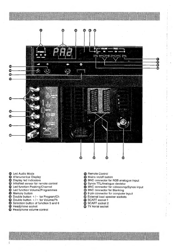
®
BNC
connector
for
videocomp/Syncs
input
@
BNC
connector
for
RGB
analogue
input
@
BNC
connector
for
Blanking
@
Mains
on/off
button
@
Syncs
T7L/Analogue
deviator
©
9
pin
connector
for
computer
input
©
External
loud
speaker
sockets
@
SCART
socket
1
@®
Remote
Contro!
@
SCART
socket
2
®
TV
Aerial
socket
5y.e
Bg
Sée
2_&
§o5
9OE
LEw
Oog
MSc
an
2&5
£66
8
Poe
c2o
&
osc
9G
pe
SSS
£25
3
S25
line.
@
aQa0g%
~~SOE
oeL2S5
Z
Fe
res
++e35
s9g5P2e,..835
gee
£855°>
SS8=SsstPPRoo0
eEoSeerz5gsefec
Losregltaacssa
Seytepeexr
Ses
SsEze
Soeelss
<28re28qqg5gq
Sag
i=
oO
s
=o
aaegg
QBSSEBRSS5E5aS
Jfaf24S0anTIT
2.0
REAR
PANEL
The
panel
at
the
rear
of
the
projector
comprises
of
all
the
necessary
components
to
esiablish
the
function
and
operative
commands,
the
input
and
output
signals
connector
and
the
convergence
and
geometry
correction
panel,
TABLE
1
illu-
strates
left
section
of
the
rear
panel,
excluding
the
correction
panel.
2.1
OPERATIVE
CONTROLS
A
series
of
buttons
offering
the
selection
of
functions
volume
(audio),
programme,
peaking/channel
and
to
memorize
some
of
the
functions.
The
alfanumerical
display
@
has
got
3
display
caracters
(of
which
the
first
indicates
a
letter
and
the
other
two
numbers)
visualizing
the
programme
currently
in
operation.
The
display
also
shows
3
light
points
@,
the
significance
of
which
wili
be
explained
later.
The
other
leds
@
give
the
operative
position
of
the
audio
signal.
There
is
also
the
on/off
mains
button
@
,
the
remote
control
socket
®
to
connect
up
to
150
m.
distance
by
cable.
A
third
control,
thus
allowing
the
possibility
of
operating
the
machine
from
an
adjacent
room.
2.2
INPUT/OUTPUT
Socket
@
allows
the
connection
of
a
headphone
of
which
the
sound
level
is
regulated
by
©
the
volume
control.
@
and
@
are
the
SCART
sockets
(or
PERITELEVISION)
to
connect
external
video
appliances.
Socket
@
is
at
norms
and
also
accepts
SUPER
VHS
signals.
There
are
also
the
TV
antenna
socket
@
and
the
external
loud
speaker
sockets
@.
In
a
separate
panel
are
situated
the
BNC
connectors
@®
for
RGB
Analogue
input,
@
is
the
BNC
connector
for
VIDEOCOMPOSITE/SYNCS
INPUT,
@
is
the
BNC
connector
for
BLANKING.
Socket
@
allows
an
external
computer
to
be
connected,
of
which
the
specifications
are
indicated
in
the
appendix.
Deviator
@
allows
the
selection
between
the
syncronism
of
TTL
or
RGB
analogue
inputs.
2.3
TUNING
PANEL
Not
represented
in
TABLE
1,
the
tuning
panel
is
described
in
another
part
of
the
manual.
In
order
to
avoid
colour
unalignment
and
subsequent
loss
of
projection
quality,
it
is
advisable
not
to
adjust
the
tuning
without
skilled
knowledge.
2.4
VISUAL
DISPLAY
Also
called
'Alfanumerical
display’
@
,
this
indicates
with
letters,
numbers
and
symbols
the
function
currently
in
opera-
tion.
The
significance
of
the
various
codes
are
explained
below.
CODE
Pr
<
b
P25]
Programmes,
or
memory
cells
on
which
the
channels
of
the
TV
stations
are
memorized
{per
tuner
model)
FAL
Allows
the
input
of
SCART
socket
no.
1
@
(Pac
|
Allows
the
input
of
SCART
socket
no.
2
@
ee
Under
display
|F7
/)
0
F#
2)
.
Visualizes
the
signal
of
standard
NTSC
4.43.
252
Aliows
the
acceptance
of
S-VHS
signal
through
scart
no.
1
Pe
Allows
the
RGB+SYNCS.
input
@
@ @
or
TIL
@.
Pet
Programme
suitable
for
VCR
with
output
in
RF,
generally
under
channel
36
(however
follow
the
instructions
of
your
VCR),
finer
tuning
than
the
frequence
of
the
VCR.
itis
also
possibie
to
receive
TV
stations.

ae
Wait
for
a
number
from
0
to
9
to
call
programmes
from
10
to
19.
fPz_]
Wait
for
a
number
from
0
to
9
to
call
programmes
from
20
to
29.
(PEt
On
display
Ptt.
abilitates
Teletext
or
Televideo
mode.
£25\¢
$[e79]
To
select
channels
of
the
television
emissions.
2.5
DISPLAY
LED
INDICATORS
Three
points
of
light
@
at
the
base
of
display
@
offer
the
following
indications:
All
lights
switch
on
when
the
projector
is
in
stand
by.
fi
ole
The
command
and
regulation
of
stereo
is
abilitated.
Three
led
@
indicates
in
which
Audio
mode
the
videoprojector
has
been
programmed.
A
8
|
STEREO
|
® ©
@
Trasmission
is
inmono
Led
@
switched
on
indicates
that
the
adjoining
functions:
Volume
and
Programmes
(research
of
no.
of
programmes)
are
abilitated.
Led
@
switched
on
indicates
that
the
adjoining
functions:
Peaking
and
research
of
no.
of
channels
are
abilitated.
NOTE:
These
two
leds
are
alternatively
inserted
by
means
of
button
@
F.
2.6
ON
SCREEN
DISPLAY
Some
indication
regarding
the
operation
of
research
or
regulation
in
course,
are
projected
on
the
screen
for
the
dura-
tion
of
5
seconds.
The
following
various
indications
concern
the
NO.
OF
PROGRAMME,
NO.
OF
CHANNEL,
TIME,
PEAKING
MEMORI-
ZING,
BRIGHTNESS,
CONTRAST,
COLOUR,
MUTE,
VOLUME,
HIGH
and
LOW
TONES,
STEREO
BALANCE.

3.0
REMOTE
CONTROL
Only
some
of
the
functions
can
be
controlied
from
the
rear
panel,
whilst
the
I.R.
Remote
control
supplied
can
operate
all
of
them
with
the
exception
of
mains
on/off
(operated
by
button
@
)
and
the
peaking
regulation.
To
activate,
the
remote
control
must
be
pointed
in
the
direction
of
sensor
€
on
the
rear
panel,
towards
the
front
sensor
situated
under
the
lenses
or
directly
towards
the
screen,
causing
a
mirror
reflection.
From
the
remote
control
you
can
operate
ail
the
functions
described
on
table
2,
only
with
the
videoprojector
supplied
with
tuner.
With
the
MONITOR
model,
which
is
supplied
with
the
same
remote
conirol,
some
of
the
functions
are
notin
Operation.
[Numerical
key
board
to
request
programmes,
channels
and
teletext
pages
E&
Recall
button
for
monitor
programme
and/or
teletext
pages.
Recail
button
for
programmes
10
to
19
{8
Recall
button
for
programmes
20
to
29
{&B
Button
to
decrease
by
one
unit
programmes/channels
,
teletext
page
and
nderpage
Button
to
increase
by
one
unit
programmes/channels,
teletext
page
and
nderpage
Memorization
button
[@
Recall
button
for
reference
value
(normalization)
EE
Wide
button
(expansion
of
sound)
82
Button
to
abilitate
stereo
command
WH
Button
to
superimpose
teletext
images
over
Tv
picture
fl
Teletext
button
TV
button
to
remove
the
teletext
image
momentarily,
remaining
in
TTX
ode
—)
Glock
and
underpage
programming
button
EE
Button
to
reveal
masked
lines
(quiz)
—&
Stop
button
to
block
the
underpage
updating
ia
P/P
button*
{©
Inversion
of
PIP/TV
image
button*
[Volume
button
&
Colour/balancing
(in
stereo
mode)
regulation
button
Ef
Brightness
tone
(in
stereo
mode)
regulation
button
£3
Contrast/bass
tone
(in
stereo
mode)
regulation
button
EZ]
Switch
off
button
(in
stand-by)
E}
Programme/channel
change
button
E&
Fine
tuning/size
regulation
button
for
PIP
E&
Bilingual
command/forced
mono
button
—
Muting
button
§
Teletext
semipage
button
(enlargement
of
characters)
—@
Autoscan
bution*
—@
Teletext
idex
page,
recall
button
Ei
Progressive
image,
stop
button*
EB
PIP
image,
stop
button*
£)
PIP
image,
shift
button*
*
Operative
only
with
appliances
with
PIP
90
board.
3.1
DISTANCE
SENSOR
When
it
is
not
possible
to
operate
from
the
projection
room
a
‘Distance
Sensor’
is
available
as
an
option.
This
is
connected
to
socket
&
on
the
rear
panel
with
a
three
pin
cable
for
up
to
a
distance
of
150
m..
The
commands
sent
are
visualized
on
the
display
lights
and
the
relative
information
is
shown
on
the
screen
for
the
duration
of
approx.
5
seconds.
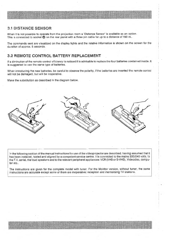
3.2
REMOTE
CONTROL
BATTERY
REPLACEMENT
If
a
diminution
of
the
remote
control
efficiency
is
noticed
it
is
advisable
to
replace
the
four
batteries
contained
inside.
It
is
suggested
to
use
the
same
type
of
batteries.
When
introducing
the
new
batteries,
be
careful
to
observe
the
polarity,
if
the
batteries
are
inverted
the
remote
control
will
not
be
damaged,
but
will
be
inoperative.
Make
the
substitution
as
described
in
the
diagram
below.
in
the
following
section
of
the
manual
instructions
for
use
of
the
videoprojector
are
described,
having
assumed
that
it
has
been
installed,
tested
and
aligned
by
a
competent
service
centre.
It
is
connected
to
the
mains
220/240
volts,
to
the
T.V.
aerial,
the
loud
speakers
and
to
the
relevant
peripheral
appliances:
VCR
(VHS
or
S-VHS)},
Videodisc,
compu-
ter
etc.,
The
instructions
are
given
for
the
complete
model
with
tuner.
For
the
Monitor
version,
without
tuner,
the
same
|
instructions
are
accurate
except
some
of
them
are
inoperative:
reception
and
memorising
TV
stations.
4.0
SWITCH
ON
With
the
appliance
compietely
switched
off,
push
button
@,
if
the
button
is
pushed
for
an
instant,
the
three
lights
come
on
@,
if
the
button
is
pushed
for
a
few
seconds,
on
display
@
P1
appears.
in
the
last
case
the
projector
selects
programme
P1
on
which
wili
have
been
memorized
a
TV
station.
4.0.1
STAND
BY
To
maintain
the
appliance
not
in
operation,
out
in
STAND-BY,
awaiting
instructions,
push
EJ
on
the
remote
control.
On
the
back
panel
the
three
points
of
light
@
will
appear.
4.0.2
SWITCH
ON
FROM
STAND
BY.
From
stand
by
the
appliance
is
made
operative
by
pushing
one
of
the
numerical
buttons
on
the
remote
control,
which
corresponds
to
the
programme
you
wish
to
see.
NOTE:
If
the
videoprojector
is
not
in
use
for
any
length
of
time
it
is
advisable
to
switch
it
off
using
button
@.
4.1
CHANNEL
SELECTION
4.1.4
FROM
REMOTE
CONTROL:
There
are
25
set
programmes
of
the
videoprojector
on
which
TV
emissions
can
be
memorized,
this
means
P1
to
P25.
Push
one
of
the
buttons
1
to
9,
the
appliance
will
tune
into
the
appropriate
channel.
To
reach
programs
P10
to
P19,
first
push
1_
followed
by
the
second
number
required;
push
2_
followed
by
the
second
number
required
to
reach
P20
to
P25.
On
display
€
will
appear
the
relative
indications.
NOTE:
At
any
programme
request,
a
series
of
information
will
appear
on
the
screen
for
approx.
5
secs.,
as
the
following
example:
Programme
Channel
Time
—
zl
The
above
example
indicates
tuning
to
programme
1
in
which
has
been
memorized
channel
18.
With
button
Ei
and/or
§
it
is
possible
to
change
the
programme
by
one
unit
up
or
down,
the
newly
selected
programme
information
will
appear
on
the
screen.
4.1.2
FROM
REAR
PANEL
Be
sure
that
Led
@
is
switched
on:
ifit
is
not,push
button
@
F
once
only.
Push
button
@
with
the
sign
+
to
increase
the
number
of
the
programme
shown
on
display,
or
with
the
to
decrease
the
programme
number.
Again
in
this
case
the
new
programme
information
will
appear
on
the
screen.

4.2
CHANNEL
SELECTION
AND
MEMORIZATION
The
selection
and
subsequent
memorization
can
be
made
only
from
the
remote
control.
With
this
procedure
it
is
possi-
ble
to
register
in
the
memory
cells
of
the
25
programmes
reserved
for
TV
channels,
any
channel
or
modify
the
existing
positions
of
them.
Establish
on
which
programme
number
(between
P1
and
P25)
you
wish
to
memorize
a
particular
TV
channel.
Press
the
relative
numerical
button.
Push
button
B§
P/C
on
the
remote
control
(on
the
display
panel
will
appear
the
letter
C
followed
by
two
numbers)
and
select
with
the
numerical
board
the
new
number
of
the
channel,
if
already
known,
otherwise
with
button
{and/or
Egit
is
possible
to
scan,
channel
by
channel,
from
0
to
99.
Having
localized
the
desired
channel,
you
can
proceed
if
necessary,
to
fine
tune,
by
means
of
buttons
Ei
pushing
it
from
one
extreme
to
the
other.
4.2.1
MEMORIZATION
Memorizing
the
selection
chosen,
push
consecutively
the
two
buttons
M
§@.
As
aconfirmation,
on
the
screen
will
be
projected
the
information:
a
ea
4.3
AUDIO
VIDEO
RANGE
CONTROLS
In
the
videoprojector
it
is
possibie
to
intervene
on
the
tuning
of
audio/video
range.
As
previously,
the
appropriate
informa-
tion
is
shown
on
the
screen.
If
the
vertical
index
is
complete,
this
indicates
that
the
range
has
been
tuned
to
is
maximum
value.
Diminishing
the
range
will
cause
the
vertical
index
to
decline.
NOTE:
If
the
new
tuning
has
not
yet
been
memorized,
it
is
possible
to
return
to
the
previous
set
value
by
pushing
button
[i
.
The
tuning,
except
for
the
example
in
paragraph
4.3.4,
can
be
made
using
the
remote
control.
Buttons
i
allow
two
types
of
tuning.
‘n
the
first
method
you
can
tune
the
audio
volu
In
the
second
method,
by
first
pushing
button
low
bass.
By
pushing
number
ff
again,
you
revert
to
the
first
type
of
tunning
described
above.
Below
you
will
find
examples
of
information
shown
on
the
screen
for
the
duration
of
approx
5
secs.,
when
carrying
out
the
tuning
procedure
of:
,
the
colour,
the
brightness
and
the
contrast.
you
can
once
again
tune
audio
volume,
the
balancing
and
high
and
VOLUME:
Regulating
the
intensity
of
the
loudspeakers
BASS
:
Regulating
the
fevel
of
low
frequency
*
In
case
of
stereo
transmission
the
word
STEREO
will
appear
on
the
screen
display.
4.3.5
NORMALIZED.
The
appliance
is
produced
with
optimal
iuning,
both
for
audio
and
video,
already
preprogrammed.
These
regulations
are
common
for
all
25
programmes,
although
they
can
also
be
modified
as
you
wish,
but
always
in
the
same
way
for
every
programme.
To
return
to
the
previous
tuning
it
is
sufficient
to
press
button
B%.
To
memorize
it
is
necessary
to
press
buttons
@
on
the
rear
panel.
The
possible
tunings
available
in
normalized
function
are:
Volume
and
Peaking
from
the
back
panel
(see
2.1
and
2.5.3)
and
using
the
remote
control,
volume,
balance,
Bass,
treble,
colour,
contrast,
brightness.
This
memorization
can
only
be
made
from
the
rear
panel.
4.3.6
PERSONALIZED
OR
PERSONAL
MEMO.
Colour,
Brightness
and
Fine
tuning
of
the
videoprojector
can
be
pretuned,
programme
by
programme,
without
any
limita-
tion
of
range.
The
personalization
can
only
be
made
from
the
remote
control
and
memorized,
programme
by
programme,
by
pressing
simultaneously
the
two
buttons
§@
.
4.4
AUDIO
MUTING
If
for
any
reason,
it
is
necessary
to
reduce
the
sound
level
immediately,
for
example
to
answer
the
telephone,
press
button
On
the
screen
will
be
projected
the
information:

4.5
MONO/STEREO
BI-LINGUAL
FUNCTIONS
The
special
design
of
the
videoprojector
offers
audio
reproduction
at
high
fidelity
and
quality,
furthermore
the
possibili-
ty
of
creating
a
STEREO
EFFECT’
even
in
mono.
*SOUND
EXPANSION’
both
in
stereo
and
mono
produce
a
dilightful
sound.
When
the
transmission
is
predisposed
it
is
possible
to
choose
the
‘SECOND
LANGUAGE’.
4.5.1
MONO
STEREO
SWITCH
Referring
to
paragraph
2.5.2
you
are
reminded
thal,
if
the
signal
processed
by
the
videoprojector
is
in
stereo,
the
two
extreme
Jed
A
and
B
on
the
rear
panel
are
switched
on,
whilst
if
the
signal
is
in
mono,
only
the
central
led
will
be
switched
on.
The
stereo
reception
can
be
‘forced’
into
mono
by
pressing
button
EJ,
on
screen
will
appear:
Peter
Tritt
meetin
CEES
ae
ened
By
pressing
Ethe
reception
will
be
returned
to
stereo
4.5.2
COMMAND
TO
WIDEN
OR
EXPAND
THE
SOUND
Use
button
[to
achieve
the
pleasing
effect
of
enlargement
of
the
sound,
both
in
Mono
and
Stereo.
The
information
projected
on
the
screen
for
approx
5
secs.
will
be:
in
Mono
in
Stereo
iu
Eee
Reema
If
the
signal
processed
by
the
videoprojector
is
in
the
form
of
two
sound
channels,
not
Stereo
but
bilingual,
the
two
sources
can
be
listened
to
separately,
one
from
the
loud
speakers,
the
other
from
a
head
phone
connected
to
socket
q)
‘on
the
rear
panel.
The
sound
level
of
the
headphones
is
adjusted
by
means
of
knob
@.
The
three
Led
Pon
the
rear
panel
indicates:
“%
@ ®
Principle
language
in
the
loud
speaker,
secondary
language
in
the
headphones.
On
the
screen
will
be
eee
Tae
ie
With
button
2
you
can
invert
the
positions
and
the
Led
will
indicate:
Principle
language
in
the
headphones,
secondary
in
the
loudspeakers.
On
the
screen
will
be
projected:
eae
Also
under
these
conditions
it
is
possible
to
create
the
Wide
effect
or
Expansion
of
the
sound
by
pressing
button
&.
The
signals
displayed
will
be
as
follows:
rr
Trisitentititsis
nen
Sift
ia
se
¢
@
language
1
in
loud
speakers,
2
in
head
phones
Hi
Steal:
Haart
om
pUuas
vera
eens
eenezinepererentan
saps
tee
°
28.
é
language
1
in
head
phones,
2
in
loud
speakers
ESE
ue
evcee
spe
ume
ety
dete
4.6
PROGRAMME
28
VIDEO-RECORDER
IN
RADIO
FREQUENCY
This
programme
contains
particular
technical
abilities
which
make
it
possible
to
better
utilize
a
VCR
with
Radio
Fre-
quency
output.
Programme
29
is
operative
only
if
the
videoprojector
is
equipped
with
the
tuner.
The
video
output
of
the
VCR
has
to
be
connected
to
the
socket
of
aerial
@
Tab.
1.
Generally
this
VCR
operates
on
channel
36:
it
is
then
necessary
to
memorize
channel
36,
after
having
had
the
necessary
fine
tuning,
on
programme
29.
See
the
instructions
for
your
VCR.
A
it
is
in
any
case
possible
to
use
channel
29
with
other
channels
dedicated
io
TV
stations.
To
reach
programme
29
from
the
remote
control
press
2_
followed
by
button
9.
5.0
LOW
FREQUENCY
VIDEO
The
videoprojector
incorporates
different
types
of
connectors
to
allow
the
use
of
apparatus
which
generates
video
signals
in
low
frequency:
Consumer
or
professional
VCR,
Video
Cameras,
Videodisc,
Video
games,
Computer
and
cthers.
The
connections
in
low
frequency
video
(from
Tab.
1
are
identified
by
& @
@
)
accept
the
video
systems
commonly
used,
such
as:
PAL,
SECAM,
NTSC
3.58
NTSC
4.43.
Consequently
it
is
possible
to
project
with
appliances
and
tapes
using
different
systems
other
than
PAL.
5.0.1
BNC
INPUT
The
BNC
@,
@,
@
are
reserved
for
RGB
+
Sync
signals
and
operates
by
programme
28,
which
will
be
explained
later.
If
during
the
videoprojection
you
intervene
in
the
video
tuning,
the
information
projected
on
the
screen
will
also
indicate
the
system
used,
in
other
words,
the
display
will
also
indicate
PAL,
SECAM,
NT1
for
NTSC
3.58,
NT2
for
NTSC
4.43.
Only
with
systems
NTSC
3.58
AND
4,43
is
the
tuning
of
HUE
and
TINT
carried
out
by
using
remote
control
button
5.0.2
CANNON
INPUT
FOR
COMPUTER
The
9
pin
connector
@
Is
brought
into
use
by
programme
28,
it
is
necessary
to
connect
signals
in
TTL,
generally
coming
from
a
personal
computer.
5.0.3
S-VHS
INPUT
The
videoprojector
is
prepared
to
accept
signals
from
VCR
in
S-VHS,
with
separate
croma
and
luminance,
which
allows
reproduction
in
colour
in
very
high
definition
and
quality.
In
this
case
the
VCR
must
be
connected
to
SCART
1
@
or
to
the
BNC
socket
@
luminance
and
BNC
&
(Red)
for
croma.
5.1
SCART
AND
BNC
CONNECTIONS
The
videoprojector
is
equipped
with
two
input
sockets
via
Scart
connectors,
this
is
for
video
equipment
in
low
freqency
which
has
the
same
type
of
connection
and
which
corresponds
to
that
mentioned
in
the
appendix.
This
equipment
can
be
VCR,
Video
camera,
Video
games,
Videodisc
etc.
With
ref.
to
Tab.
1
the
two
sockets
are
identified
as
follows:
Socket
1
@
.
Socket
2
@
Signals
to
the
two
sockets
cannot
be
projected
simultaneously.
The
Scart
connector
also
accepis
signals
RGB
+
SYNC
Analogue.
The
two
Scart
sockets
also
have
output
video,
there-
fore
it
is
possible
to
record
the
signals
in
projection.
The
VGR
is
divided
into
two
categories:
one
which
is
equipped
with
the
correct
internal
connection
which
brings
AUTO-
MATIC
COMMUTATION
TENSION,
the
other
does
not
have
this
connection.
NOTE:
The
appliances
connected
to
SCART
and
BNC
@
sockets
can
operate
in
one
of
the
four
video
systems:
PAL,
SECAM,
NTSC
3,58
and
NTSC
4.43,
with
automatic
connection
to
the
first
three
systems,
whilst
the
NTSC
4.43
(NT2)
requires
utilization
of
programme
26,
as
later
described.

5.1.1
APPLIANCES
WITH
INTERNAL
ABILITATION
It
is
possible
to
connect
2
VCR
to
sockets
1
and
2:
the
first
appliance
which
comes
into
PLAY
determines
its
inseriion
independently
of
the
programme
in
use
at
that
moment,
with
the
exception
of
programme
26.
:
—
To
insert
the
other
VCR,
press
button
0
(zero)
on
the
remote
control
and
prepare
the
VCR
for
PLAY.
—
By
pushing
button
0
again
the
previous
input
is
returned
to
play
—
To
leave
this
programme,
ask
for
another
programme
other
than
0
or
P26.
5.1.2
APPLIANCES
WITHOUT
COMMUTATION
OF
TENSION
Push
button
0
on
the
remote
contro!
once
onlly
to
abilitate
socket
1
to
connector
21.
The
information
displayed
will
be
Push
button
0
a
second
time
to
abilitate
socket
1
to
connector
22.
The
information
displayed
will
be
[F#2)
To
leave
this
programme,
ask
for
another
programme
other
than
0
or
P26.
5.1.3
VIDEO
COMPOSITE
TO
BNC
Many
professional
video
apparatus,
videocamera
or
VCR,
have
video
output
in
LOW
FREQUENCY
on
BNC
connector.
Via
this
socket
it
is
therefore
possible
to
project
the
signals.
BNC
@
Is
also
identified
as
VIDEO
IN/SYNCS,
From
the
point
of
view
of
the
programme
input
is
comparable
to
the
input
1
on
SCART.
To
abilitate
see
instructions
§
5.1.2.
NOTE
lf
the
two
apparatus
on
BNC
and
SCART
are
switched
on
simultaneously,
the
two
signals
will
mix
resulting
in
a
confused
projection,
!t
is
therefore
not
advisable
to
connect
to
BNC
VIDEO
IN
and
SCART
1
simultaneously.
§.2
PROGRAMME.26
NTSC
4.43
The
videoprojector
has
been
developed
to
operate
in
the
four
video
systems.
The
particular
system
in
operation
is
displayed
on
the
screen
for
5
secs.
when
the
brightness,
contrast
or
colour
buttons:
on
the
remote
control
are
pressed.
If
the
videosystem
in
use
is
NTSC
4.43
(NT2)
programme
26
is
required,
before
proceeding
to
the
operation
described
in
para,
5.1,
This
is
the
case
should
the
input
signals
be
via
SCART
or
BNC
VIDEO
IN.
With
this
system
the
information
on
display
will
be
NT2.
You
are
reminded
that
in
both
systems,
NTSC
3.58
and
4.43,
the
correction
of
HUE
and
TINT,
is
made
by
pressing
button
@
on
the
remote
control,
as
with
FINE
TUNING’.
5.3
PROGRAMME
27
S-VHS
Apparatus
with
the
new
S-VHS
System
which
present
LUMINANCE
AND
CROMINANCE
separately,
must
be
inserted
by
SCART
&
or
BNC
@&
.
The
connections
of
which
are
described
in
the
appendix.
Ask
for
programme
27:
on
display
and
on
the
screen
the
information
shown
will
be
(:5:]
5.4
PROGRAMME
28
RGB
ANALOGUE
AND
TTL
Call
programme
28.
The
RGB
analogue
signals
must
be
connected
to
BNC
@,
which
is
3
connectors
respectively
marked
R,
G,
B.
The
Sync.
analogue
signais.
V+H
are
applicable
to
BNC
@.
BNC
@
accepts
Blanking
signals.
Bring
deviator
€8
towards
the
word
ANALOGUE.
§.4.1
SIGNALS
IN
TTL
TTL
signals
are
RGB
signals
in
digital
form,
generally
coming
from
a
persona!
computer.
The
connection
is
made
via
the
9
pin
standard
connector
@.
The
characteristics
of
the
computer
abilitate
it
to
work
with
the
videoprojector
and
the
description
of
the
contacts
are
explained
in
the
appendix.
The
synchronism
can
be
positive
or
negative.
The
vertical
frequence
of
the
signal
can
be
50
Hz
or
60
Hz
with
automatic
recognition.
Deviator
@
must
be
moved
towards
TTL
+

6.0
TELETEXT
AND
CLOCK
FUNCTION
The
videoprojector
is
equipped
with
a
TTX
board
which
allows
the
projection
of
teletext
pages
subject
to:
4°
The
videoprojector
is
complete
with
tuner
and
has
in
projection
a
TV
station
which
offers
this-service.
2°
The
monitor
version
of
videoprojector,
without
tuner,
as
a
VCR
connected
via
SCART
@
or
@.
This
VCR
must
reproduce
a
TV
station
which
offers
this
service.
The
teletext
board
can
memorize
8
pages
(the
following
6,
the
previous
page
and
the
one
in
view).
The
memory
is
not
only
for
the
page,
but
also
for
the
underpage
from
which
any
pages
are
denoted.
6.1
CLOCK
If
directly
or
indirectly,
the
videoprojector
is
operating
with
a
suitable
station,
press
the
remote
control
button
§@
and
in
the
top
right
hand
corner
of
the
screen
the
time
will
be
shown,
6.2
TELETEXT
The
control
is
always
made
via
the
remote
control,
subject
io
there
being
one
of
the
two
conditions
described
above.
Explained
below
are
the
functions
of
each
button,
the
symbols
for
which
are
to
the
left
of
the
description.
6.2.1
TELETEXT
BUTTON
TTX
This
is
a
command
with
a
double
function.
The
first
push
brings
the
system
into
teletext
mode
and
on
display
will
appear
PTT.
With
a
second
push
the
previous
TV
programme
is
returned,
cancelling
all
teletext
junctions,
with
the
exception
of
the
clock.
6.2.2
INDEX
PAGE
BUTTON
(}
@
This
button
requires
page
100,
which
generally
is
the
index
page
and
cancels
the
command
of
the
programme
page.
6.2.3
NUMERICAL
KEYBOARD
ER
The
buttons
from
0
to
9
can
be
used
to
select
the
mumber
of
the
page
and
to
set
the
programme
of
the
page.
6.2.4
SUPER-IMPOSING
BUTTON
;
Produces
super-imposing
of
teletext
pages
over
re-existing
TV
programmes.
Press
again
to
cancel
effect.
6.2.5
SEMIPAGE
BUTTON
Devides
the
page
into
two
semipages,
double
height.
The
first
two
touches
produce
the
described
effect
and
present
the
two
half
pages;
with
the
third
touch
the
normal
dimension
of
page
is
restored,
presented
in
full.
6.2.6
REVELATION
BUTTON
@)
my
Allows
viewing
of
masked
rows
containing
solutions
of
a
quiz
or
game.
6.2.7
TV
BUTTON
3]
Allows
viewing
of
TV
programmes
whilst
staying
in
teletext
mode.
6.2.8
STOP
BUTTON)
One
page
is
stopped:
blocks
the
automatic
change
to
the
underpages.
Press
again
to
cancel
the
effect
or
request
a
new
page.
6.3
TELETEXT
MODE
Having
tuned
to
a
TV
station
which
is
suitable
to
receive
teletext,
press
buttons
§.
With
the
numerical
buttons,
press
the
number
(generally
three
digits)
of
page
you
are
interested
in.
If
the
teletext
programme
consists
of
a
sequence
of
pages,
press
button
B%
o
advance
the
page
or
bution
to
return
to
the
previous
page.
Remember
that
the
memory
contains
6
pages
in
advance
of
the
one
requested.
See
the
description
of
the
other
buttons
to
obtain
their
particular
functions.
Press
f@
again
to
leave
the
teletext
mode.
6.3.1
UNDERPAGES
-To
give
an
example
of
a
required
page
with
underpages:
Page
306
with
6
underpages
marked
1/6
to
6/6.
Press
button
ff
to
block
or
stop.
After
certain
time,
press
button
B%
to
advance
the
underpages
and/or
button
§@
to
move
them
backwards.
6.3.2
PROGRAMMING
UNDERPAGES
To
read
a
particular
page,
for
example:
At
the
request
of
page
306
the
indication
received
is
3/6,
but
the
page
desired,
without
going
through
the
complete
cycle,
is
1/6.
Press
button
fg,
in
the
top
right
hand
side
of
the
screen
will
appear
the
letter
T,
followed
by
4
zeros.
Than
press
the
number
of
the
desired
page,
with
4
digits.
In
the
case
f
1/6,
this
will
be
0001.
Press
button
(@,
after
a
few
seconds
the
number
of
page
required
will
appear.
Press
button
fj
again
to
visualize
the
page.
To
leave
the
programming
mode
press
button
fy.
7.0
P.LP
FUNCTION
(PICTURE
IN
PICTURE)
This
option
(which
can
be
plugged
into
the
videoprojector
at
any
time)
via
the
remote
control
allows
the
simultaneous
rojection
of
2
images,
coming
from
2
different
sources:
one
internal
from
a
T.V.
programme
and
another
from
the
input
SCART
1
or
2.
The
second
image
is
placed
in
a
window
of
small
dimension,
the
size
of
which
can
be
varied
and
is
positionable
in
any
one
of
the
4
corners
of
the
screen.
7.0.1
BUTTON
P/P
By
pressing
this
button,
in
the
top
left
hand
corner
will
appear
a
window
with
the
image
transmitted
from
an
external
source
connected
to
the
videoprojector
via
the
scart
socket.
If
there
is
no
connection
to
the
SCART
socket,
of
an
external
source,
the
image
will
be
black.
To
leave
the
P.I.P.
mode
press
button
§
again.
7.0.2
INVERSION
PIP/TV
BUTTON
@)
@
By
pressing
this
button
you
obtain
the
inversion
of
the
two
images.
The
result
being
that
the
image
which
was
in
the
window
now
appears
in
the
full
screen
and
viceversa.
Press
the
button
again
to
restore
the
initial
image.
7.0.3
PIP
SHIFT
BUTTON
CB
By
pressing
this
button
it
is
possible
to
shift
the
window
image
through
the
four
comers
of
the
screen,
7.0.4
PIP
SIZE
IMMAGE
BUTTON
6
By
pressing
the
>
part
of
the
button
you
obtain
an
enlargement
of
the
image,
by
up
to
approx.
1/4
of
the
screen.
By
pressing
the
<
part
of
the
button
you
obtain
a
reduction
of
image
size
to
approx.
1/20
of
the
screen.
7.9.5
PROGRESSIVE
STOP
BUTTON
FOR
PIP
IMAGE
[33]
By
pressing
this
button,
when
the
P.I.P
is
the
normal
size,
you
obtain
an
effect
of
progressive
image
(up
to
3
images,
with
2
touches
of
the
button,
in
the
norma!
size
and
up
to
6
images,
with
5
touches
of
the
button,
in
the
small
size)
with
an
image
(the
last
one
requested)
in
movement
and
the
others
in
freeze.
With
another
press
of
the
button
you
return
to
the
original
condition.
It
is
possible,
with
button
EH,
to
choose
the
image
that
you
want
to
see
in
movement.
Pressing
>
moves
the
window
from
top
bottom
and
pressing
<
viceversa.
The
effect
of
the
moving
image
is
possible
on
the
left
or
right
side
of
the
screen
by
pressing
button
@.
7.0.6
STOP
BUTTON
FOR
PIP
IMAGE
GQ
a
By
pressing
this
button
the
image
in
the
window
is
frozen,
Under
these
conditions
acting
on
analogue
tuning
(colour,
brightness,
contrast)
you
modify
the
full
screen
image
only,
whilst
with
the
P.I.P
in
movement
the
same
tuning
modifies
only
on
the
P.I.P,
image.
7.0.7
AUTOSCANNING
BUTTON
&
By
pressing
this
button
you
obtain
a
scanning
divided
into
4
programmes.
This
scanning
presents
at
the
centre
the
image
trasmitted
by
the
station,
to
the
left
the
number
of
the
programme
and
to
the
right
the
number
of
the
memorized
channel.
The
reference
of
programmes/channei
are
represented
by
different
colours,
the
same
colours
which
are
on
the
remote
control.
To
request
the
desired
programme
you
can
press
either
the
relatively
coloured
button
or
the
number
corresponding
to
the
number
of
the
programme.
With
the
buttons
+
and
—,
itis
possible
to
choose
the
group
of
programmes
that
you
wantto
put
in
monitor
(from
1
to 4,
from
5
to
8,......
from
20
to
24).
The
four
images
are
presented
one
in
movement
and
three
in
freeze.
They
are
updated
sequentially
every
1-2
secs.
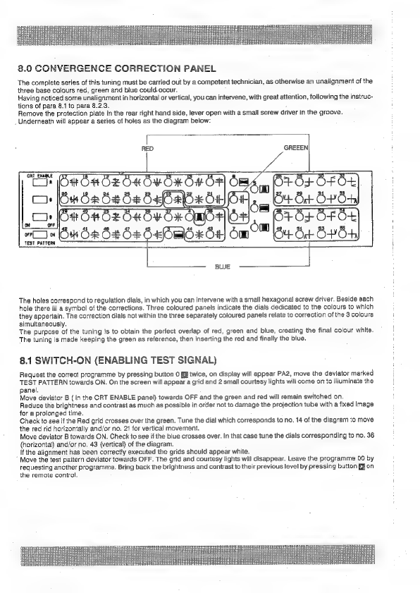
8.0
CONVERGENCE
CORRECTION
PANEL
The
complete
series
of
this
tuning
must
be
carried
out
by
a
competent
technician,
as
otherwise
an
unalignment
of
the
three
base
colours
red,
green
and
blue
could-occur.
Having
noticed
some
unalignment
in
horizontal
or
vertical,
you
can
intervene,
with
great
attention,
following
the
instruc-
tions
of
para
8.1
to
para
8.2.3.
Remove
the
protection
plate
in
the
rear
right
hand
side,
lever
open
with
a
small
screw
driver
in
the
groove.
Underneath
will
appear
a
series
of
holes
as
the
diagram
below:
RED
GREEEN
TEST
PATTERH
The
holes
correspond
to
regulation
dials,
in
which
you
can
intervene
with
a
small
hexagonal
screw
driver.
Beside
each
hole
there
is
a
symbol
of
the
corrections.
Three
coloured
panels
indicate
the
dials
dedicated
to
the
colours
to
which
they
appertain.
The
correction
dials
not
within
the
three
separately
coloured
panels
relate
to
correction
of
the
3
colours
simultaneously.
The
purpose
of
the
tuning
is
to
obtain
the
perfect
overlap
of
red,
green
and
blue,
creating
the
final
colour
white.
The
tuning
is
made
keeping
the
green
as
reference,
then
inserting
the red
and
finally
the
blue.
8.1
SWITCH-ON
(ENABLING
TEST
SIGNAL)
Request
the
correct
programme
by
pressing
button
0
E&
twice,
on
display
will
appear
PA2,
move
the
deviator
marked
TEST
PATTERN
towards
ON.
On
the
screen
will
appear
a
grid
and
2
small
courtesy
lights
will
come
on
to
illuminate
the
panel.
Move
deviator
B
(in
the
CRT
ENABLE
panel)
towards
OFF
and
the
green
and
red
will
remain
switched
on.
Reduce
the
brightness
and
contrast
as
much
as
possible
in
order
not
to
damage
the
projection
tube
with
a
fixed
image
for
a
prolonged
time.
Check
to
see
if
the
Red
grid
crosses
over
the
green.
Tune
the
dial
which
corresponds
to
no.
14
of
the
diagram
to
move
the
red
rid
horizontally
and/or
no.
21
for
vertical
movement.
Move
deviator
B
towards
ON.
Check
to
see
if
the
blue
crosses
over.
In
that
case
tune
the
dials
corresponding
to
no.
36
(horizontal)
and/or
no.
43
(vertical)
of
the
diagram.
If
the
alignment
has
been
correctly
executed
the
grids
should
appear
white.
’
Move
the
test
paitern
deviator
towards
OFF.
The
grid
and
courtesy
lights
will
disappear.
Leave
the
programme
00
by
requesting
another
programme.
Bring
back
the
brightness
and
contrast
to
their
previous
level
by
pressing
button
RZ
on
the
remote
control.
Other manuals for SVT-150
1
Table of contents
Other Seleco Projector manuals


