Select Shops Select Blinds Z-125 User manual

MUST
Do not twist the cord.
CHILD/SAFETY CHAIN TENSIONER INSTALLATION
STOPPER INSTALLATION
STEP 4 - APPLIES TO CHAIN OPERATION ONLY
MANUAL OPERATING INSTRUCTIONS
MAINTENANCE & CARE
Roller Shade Instructions |
Roller Shade Instructions
Tape Measure Power Drill / Screwdriver PencilLevel
Screws End CapsShade Brackets
Idler-end
Bracket
Clutch-end
Bracket
Roller Shade
Idler side
TMTM
Control Side
Ball Stoppers
Valance
If Ordered If Ordered For Chains Only
*Note: Returns are optional
L Bracket
STEP 1 - VALANCE INSTALLATION (If Ordered)
B - For OUTSIDE Valance, mark the location of the
A -
REQUIRED TOOLS FOR INSTALLATION
COMES WITH YOUR KIT
ROLLER SHADE INSTRUCTIONS
• Valance must be installed as a rst step before the Roller Shade. If you didn’t order a Valance proceed to Step 2.
NOTES
distance
distance
Roller Shade Instructions |

STEP 2 - ROLLER SHADE INSTALLATION
BRACKET INSTALLATION
Inside / Outside Mount:
Clutch Bracket
Idler Bracket
• Before fully installing your brackets, note the dierence
between the clutch and idler brackets.
• In order to ensure the shade does not fall out of the brackets,
it is critical that the idler pin is securely compressed by
at least 1/4” upon installation If pin is too loose, shade may
fall out of brackets. If pin is compressed too tightly,
shade may not operate properly.
• End caps are not required when installing a valance.
NOTES
Ordered Shade Width
Inside Position
Outside Position
A
A
B
B
Roller Shade Instructions |
Roller Shade Instructions
Regular Roll
STEP 3 - SHADE INSTALLATION / HANGING THE SHADE
Reverse Roll
B - E
A -
Insert the idler-end into the
• Ensure fabric rolls in the direction you specied (regular or reverse roll)
• Your control side depends on what you specied
• Proper installation requires the idler pin to be permanently compressed by at least 1/4” once mounted in the brackets.
If necessary, the brackets may need to be installed closer together for a secure t and to prevent shade from falling out of the brackets.
NOTES
NOTES
Idler side
Fabric rolls o the
back of the tube,
closest to the window
Fabric rolls o the
front of the tube,
into the room
Roller Shade Instructions |
Roller Shade Instructions

STEP 2 - ROLLER SHADE INSTALLATION
BRACKET INSTALLATION
Mounting Brackets consist of an idler end and a clutch end bracket. Brackets can be positioned for inside mount
or outside mount installations. Install the brackets according to L or R side controls.
Inside / Outside Mount: Using a steel measuring tape,
measure the distance from the outside edge of each
bracket according to the ordered shade width.
Mark the screw location on the mounting surface with
a pencil, snap end caps onto brackets (if ordered).
Fasten brackets according to Left or Right side controls
in the marked locations using the screws provided.
Ensure brackets are secure, leveled, parallel and facing
towards each other.
Clutch Bracket
Idler Bracket
• Before fully installing your brackets, note the dierence
between the clutch and idler brackets.
• In order to ensure the shade does not fall out of the brackets,
it is critical that the idler pin is securely compressed by
at least 1/4” upon installation If pin is too loose, shade may
fall out of brackets. If pin is compressed too tightly,
shade may not operate properly.
• End caps are not required when installing a valance.
NOTES
Ordered Shade Width
Idler pin must compress at least 1/4” to ensure
shade is properly secured in the brackets.
Inside Position
Outside Position
A
A
B
B
2
Roller Shade Instructions |
Roller Shade Instructions
Regular Roll
STEP 3 - SHADE INSTALLATION / HANGING THE SHADE
Reverse Roll
B - Ensure hook on the clutch side is pointing downward
and securely fastens into the “+” shaped opening of the
clutch bracket.
Hook into “+”
to secure.
Hook the clutch end into the “+”
shaped opening in the bracket.
Ensure the hook is pointing
downward.
A - The idler end has spring-loaded pin that allows
it to compress in /out. Insert the idler-end into the
idler-end bracket, compress and hook the clutch
side into the “+” shape of the clutch bracket.
• Ensure fabric rolls in the direction you specied (regular or reverse roll)
• Your control side depends on what you specied
• Proper installation requires the idler pin to be permanently compressed by at least 1/4” once mounted in the brackets.
If necessary, the brackets may need to be installed closer together for a secure t and to prevent shade from falling out of the brackets.
NOTES
NOTES
Idler side
Fabric rolls o the
back of the tube,
closest to the window
Fabric rolls o the
front of the tube,
into the room
3
Roller Shade Instructions |
Roller Shade Instructions

CHILD/SAFETY CHAIN TENSIONER INSTALLATION
MUST
p-clipp-clip
p-clipp-clip
Do not twist the cord.
STOPPER INSTALLATION
STEP 4 - APPLIES TO CHAIN OPERATION ONLY
MANUAL OPERATING INSTRUCTIONS
MAINTENANCE & CARE
Roller Shade Instructions |
Roller Shade Instructions
Tape Measure Power Drill / Screwdriver PencilLevel
Screws End CapsShade Brackets
Idler-end
Bracket
Clutch-end
Bracket
Roller Shade
Idler side
TMTM
Control Side
Ball Stoppers
Valance
If Ordered If Ordered For Chains Only
*Note: Returns are optional
L Bracket
STEP 1 - VALANCE INSTALLATION (If Ordered)
B - For OUTSIDE Valance, mark the location of the
A -
REQUIRED TOOLS FOR INSTALLATION
COMES WITH YOUR KIT
ROLLER SHADE INSTRUCTIONS
• Valance must be installed as a rst step before the Roller Shade. If you didn’t order a Valance proceed to Step 2.
NOTES
distance
distance
Roller Shade Instructions |

(6SULQJ'ULYH70+DQGOHΖQVWDOODWLRQΖQVWUXFWLRQV
©2020 Elite Window Fashions 6SULQJ'ULYH70 )UHTXHQWO\$VNHG4XHVWLRQV
635Ζ1*'5Ζ9(70 )5(48(17/<$6.('48(67Ζ216
6SULQJ'ULYH70 )UHTXHQWO\$VNHG4XHVWLRQV
©2020 Select Shops 6SULQJ'ULYH70+DQGOHΖQVWDOODWLRQΖQVWUXFWLRQV
6ORZO\DQGFDUHIXOO\VOLGH
WKHKDQGOHRQWRWKH
ERWWRPUDLO
:KHQFHQWHUHGWKH
KDQGOHLVIXOO\
RSHUDWLRQDO
635Ζ1*'5Ζ9(70+$1'/(Ζ167$//$7Ζ21
5HPRYHWKHKDQGOHIURPLWVSDFNDJLQJ6HFXUHWKHERWWRPUDLOZLWK
RQHKDQGWRSUHYHQWWKHVKDGHIURPPRYLQJ
ǫ 7KHUHLVQRJXDUDQWHHWKH\ZLOORSHUDWHDWWKHVDPHVSHHG,I\RXKDYHWZR
GLIIHUHQWVL]HVWKHUDWHRIH[WHQVLRQLVQRWJXDUDQWHHGWREHWKHVDPH$OWHUQDWLYHO\HYHQWKHVDPHVL]H
VKDGHVFDQH[WHQGRUUHVFLQGDWGLIIHUHQWVSHHGV
ǫ 1RWSRVVLEOHLWVORFNHGLQDQGSUHGHWHUPLQHG7KHV\VWHPFDQQRWEHDGMXVWHG,I
WKHVKDGHLVQRWULVLQJTXLFNO\RUWKHUHLVWRRPXFKSUHVVXUHRQWKHUROOFDUHIXOO\LQVWDOO;;;RQSLQ
XQIRUWXQDWHO\WKHUHLVQRURRPWRZLQGDQ\PRUH
ǫ &DQRQO\EHDGMXVWHGLI\RXUHPRYHWKHLQWHUQDOVSULQJDQGDGMXVWLW
PDQXDOO\$GMXVWPHQWVRQGLIIHUHQWKHLJKWVDQGIDEULFZHLJKWVQRWDOOFDQEHPRGLILHG
ǫ6SULQJRQPPPD\GHWDFKGXULQJVKLSSLQJ7KLVZLOOEHQRWLFHDEOHLIWKHIROORZLQJ
KDSSHQV
vVKDGHURFNHWVRII
vEUDNHGRHVQWZRUN
<RXFDQIL[WKLVRQDQ2SHQ5ROO6KDGHE\VLPSO\ORFDWLQJWKHSDUWDQGUHDWWDFKLQJLW
635Ζ1*'5Ζ9(70
+$1'/(237Ζ216
&OHDUKDQGOH
ZLWKWDVVOH
&OHDUKDQGOH

4

5

SMART CONTROLLER
powered by Neo Smart Blinds
ENGLISH
SETUP CODE
CODE DE CONFIGURATION
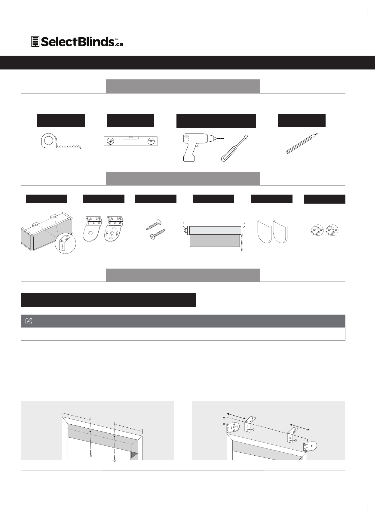
System requirements
• A strong WiFi signal (3 bars or more) in the location where you
will setup your Smart Controller.
• The Smart Controller only supports 2.4GHz WiFi (IEEE 802
11b/g/n), not 5GHz. WiFi security needs to be set to WPA-PSK or
WPA2-PSK.
• A smartphone or tablet running Android 5.0 (Lollipop) or
higher, or iOS 8 or higher is needed.
Troubleshooting
The home WiFi doesn’t appear in the step 4
Try rescanning, if the problem persists, you will need to reposition
the Smart Controller to a place with stronger WiFi signal. In this
case, exit the process (tap on the menu, then tap Your Rooms),
replace the Smart Controller and start over.
The Smart Controller LED in the bottom is not blinking blue
The process fails in the last step
Press the S button for 10 seconds, then press the R button once
and start over. Pay special attention when typing the WiFi
password.
Need more help?
Visit neosmartblinds.com/smartcontroller for detailed instructions
about how to use the app and troubleshooting.
Integrations
Smart home devices
Visit neosmartblinds.com/smartcontroller-integrations for detailed
information about connecting to Amazon Alexa, Google Home
and other systems.
Control4
name, your email and your company’s name. This information is
necessary to always send to you any further driver update.
Legal Information
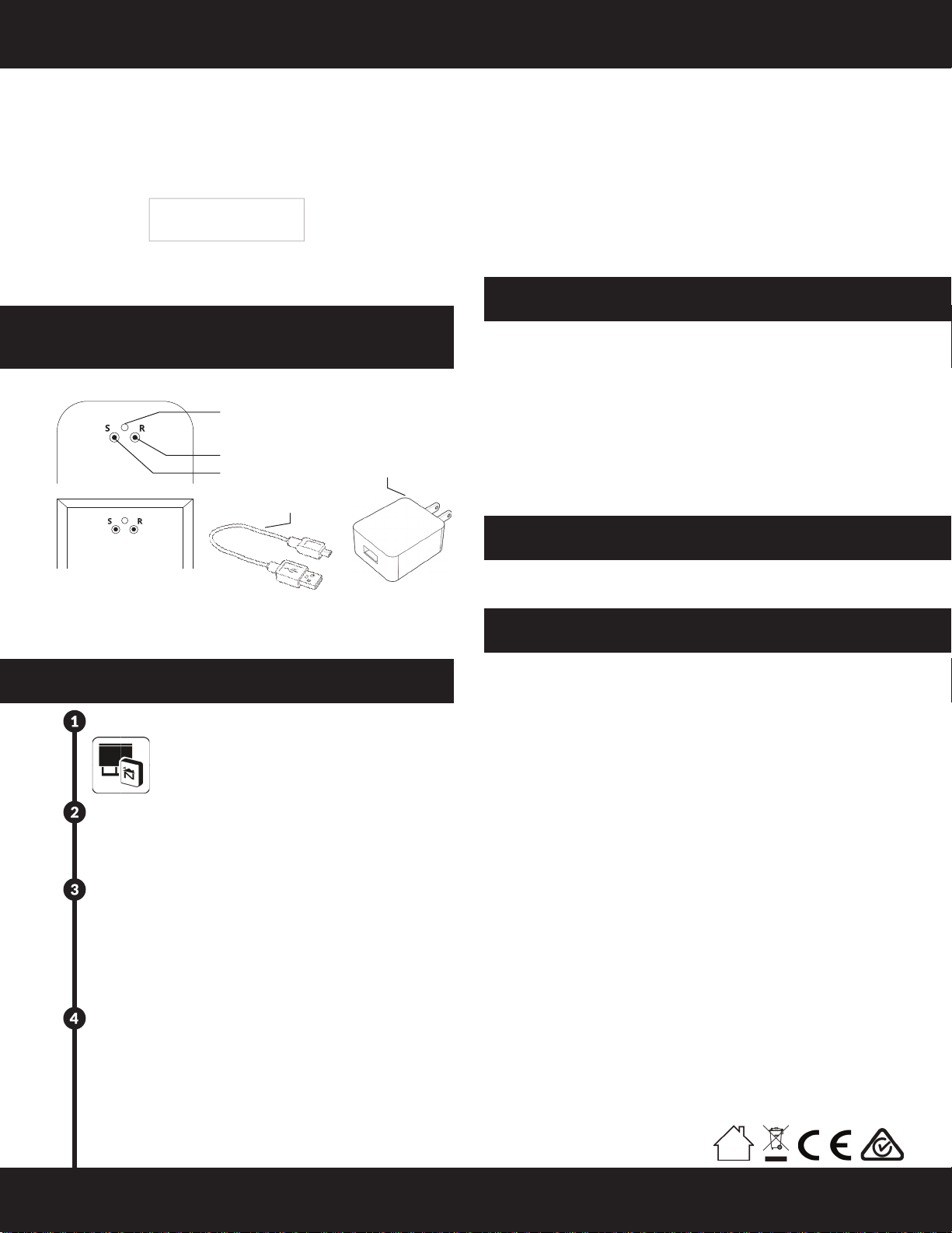
Getting to know your
Smart Controller
Smart Controller Status:
Flashing blue - Hotspot available
Flashing green - Connecting to the WiFi network
Pulsing cyan/blue-green - Connected to the Internet
Getting Started
Download the Neo Smart Blinds app
Download the app to your phone or tablet by
searching Neo Smart Blinds on Google Play
or the App Store.
Note: Do not install Neo Smart Blinds Blue
Plug in your Smart Controller in reach of your home WiFi
Choose a place not too far from your home router or a place
you know has good WiFi signal strength. You will be able to
change its location after, if necessary.
Create an account and choose the setup code written
on the cover
After opening the app, tap on Create one to create
a new account. Enter a valid email address and choose
a password, select the region time zone from the place
where the Smart Controller will be located. Choose the
setup code written in the cover and tap on Register.
Follow the app step by step to add the Smart Controller
Have in hand the home WiFi password. It will be necessary
to connect the Smart Controller to the Internet.
Note: Some Android users won’t be connected quickly to the
hotspot. If it is the case, please wait about 10 seconds
before returning to the app. During this time, your device may
notify you that the hotspot does not have Internet access,
and will prompt you whether you want to remain connect-
ed. You need to select the option that will allow you to keep
connected before returning to the app.
FCC
This equipment has been tested and found
to comply with the limits for a Class B digital
device, pursuant to Part 15 of the FCC Rules.
These limits are designed to provide reason-
able protection against harmful interference
in a residential installation. This equipment
generates uses and can radiate radio
frequency energy and, if not installed and used
in accordance with the instructions, may cause
harmful interference to radio communications.
However, there is no guarantee that interfer-
ence will not occur in a particular installa-
tion. If this equipment does cause harmful
interference to radio or television reception,
which can be determined by turning the
equipment off and on, the user is encouraged
to try to correct the interference by one of the
following measures:
• Reorient or relocate the receiving antenna.
• Increase the separation between the
equipment and receiver.
• Connect the equipment into an outlet
on a circuit different from that to which the
receiver is connected.
• Consult the dealer or an experienced radio/
TV technician for help
Contains transmitter module FCC ID:
COFWMNBM11
To comply with FCC/IC RF exposure limits for
general population/ uncontrolled exposure,
the antenna(s) used for this transmitter must
be installed to provide a separation distance
of at least 20 cm from all persons and must not
be co-located or operating in conjunction with
any other antenna or transmitter.
IC
This device complies with Industry Canada’s
licence-exempt RSSs. Operation is subject to
the following two conditions:
• This device may not cause interference;
and
• This device must accept any interference,
including interference that may cause unde-
sired operation of the device.
This device meets the exemption from the
routine evaluation limits in section 2.5 of
RSS102 and users can obtain Canadian infor-
mation on RF exposure and compliance.
Contains transmitter module IC:
10293A-WMNB11
This End equipment should be installed and
operated with a minimum distance of 20 centi-
meters between the radiator and your body.
micro-USB port
power adapter
micro-USB cable
LED indicator
Smart Controller Status
Reset button
Setup button
L2019
E8965
N2421
This manual suits for next models
2
Table of contents
Popular Indoor Furnishing manuals by other brands

Möbel AS
Möbel AS KLTS62321 Assembling Instruction

Englefield
Englefield VALENCIA installation instructions

2K Furniture Designs
2K Furniture Designs D505-T Assembly instructions

aspenhome
aspenhome I256-6052 Assembly instructions

Vinsetto
Vinsetto 921-451 Assembly & instruction manual

Argos Home
Argos Home 246/4675 Assembly instructions

highwood
highwood Deck Storage Box Assembly guide

OVE
OVE SIMON 24 installation manual

OVE
OVE AYSEL 42 installation manual

Damiano Latini
Damiano Latini Giostra-L H208 Assembly instructions

Lifestyle Solutions
Lifestyle Solutions HENNEPIN 660A001WHT Assembly instructions

Forte
Forte Harllson EasyKlix HLTK231REC Assembling Instruction