Select Audio 8 User manual

Economy functional & digital audio access systems
Audio 8 & 16
Functional & Digital
Installation Manual
07/06/2002
S
electLine
S
electine
Select Manufacturing Limited
Unit H1 - The Seedbed Centre - Wyncolls Road - Severalls Business Park - Colchester - Essex CO4 9HT
Telephone +44(0)1206 855800 - Facsimile +44(0)1206 855801
Functional & Digital Audio
Digital Video
Revision 1.08 Date: 05/12/2011

Digital Network & Power Overview
Digital System Flat Programming Form
Digital Entrance Panel Programming Instructions
Digital System Summary
Digital System wiring colour codes
Digital & Landing Entrance Panel
Digital Entrance Panel wiring detail
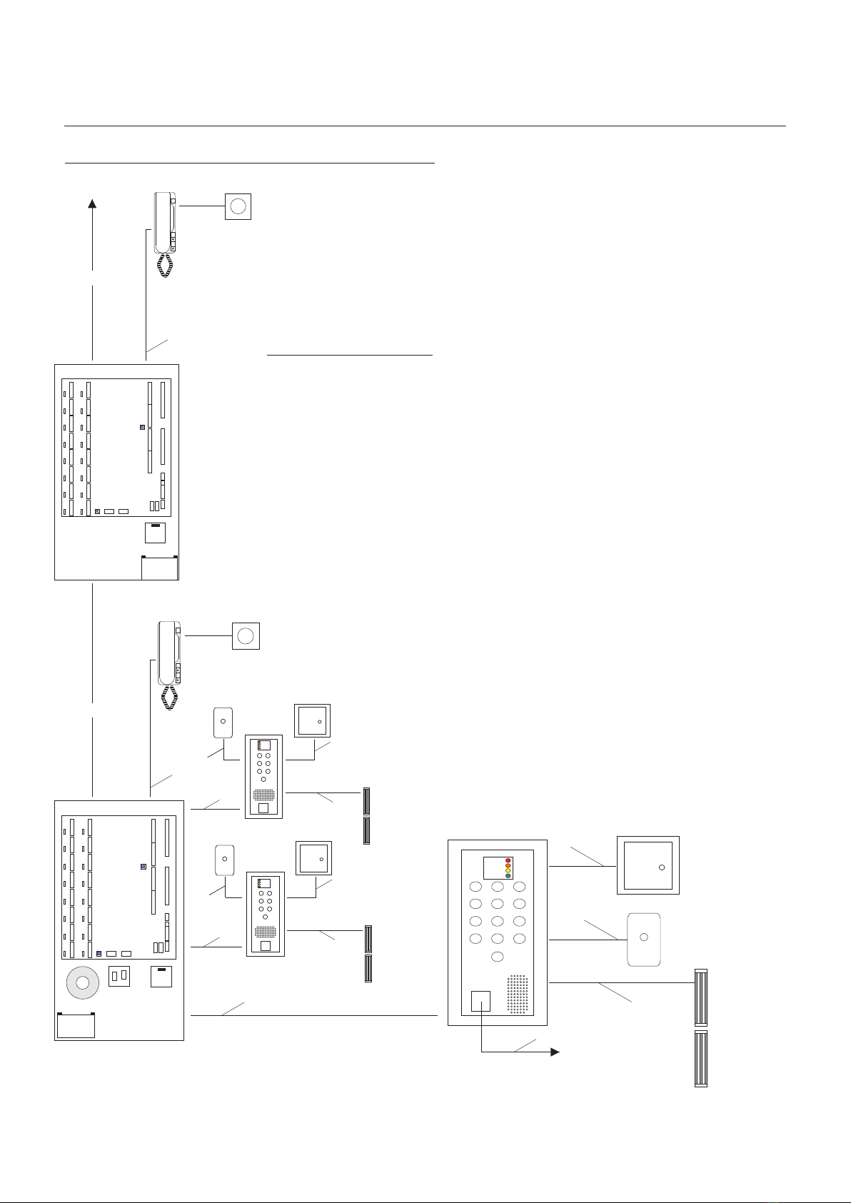
System Wiring Overview
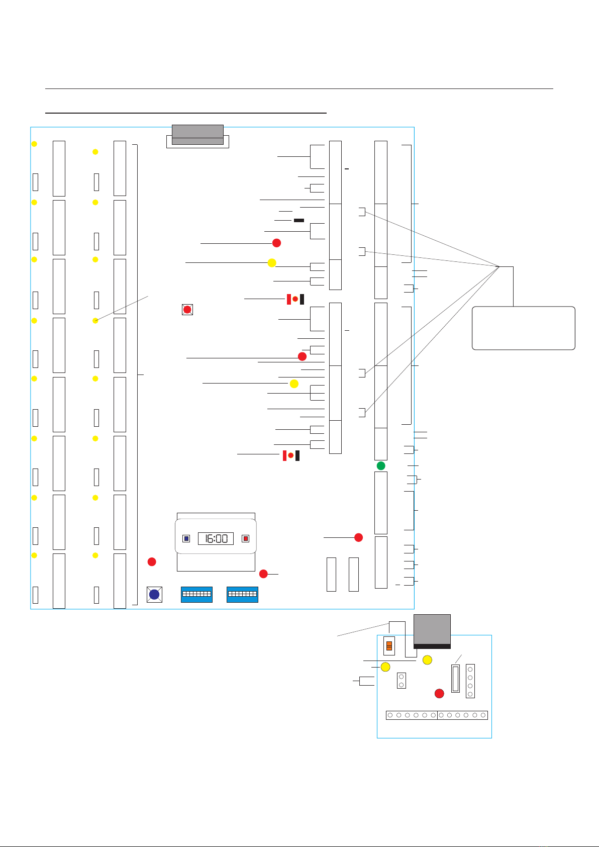
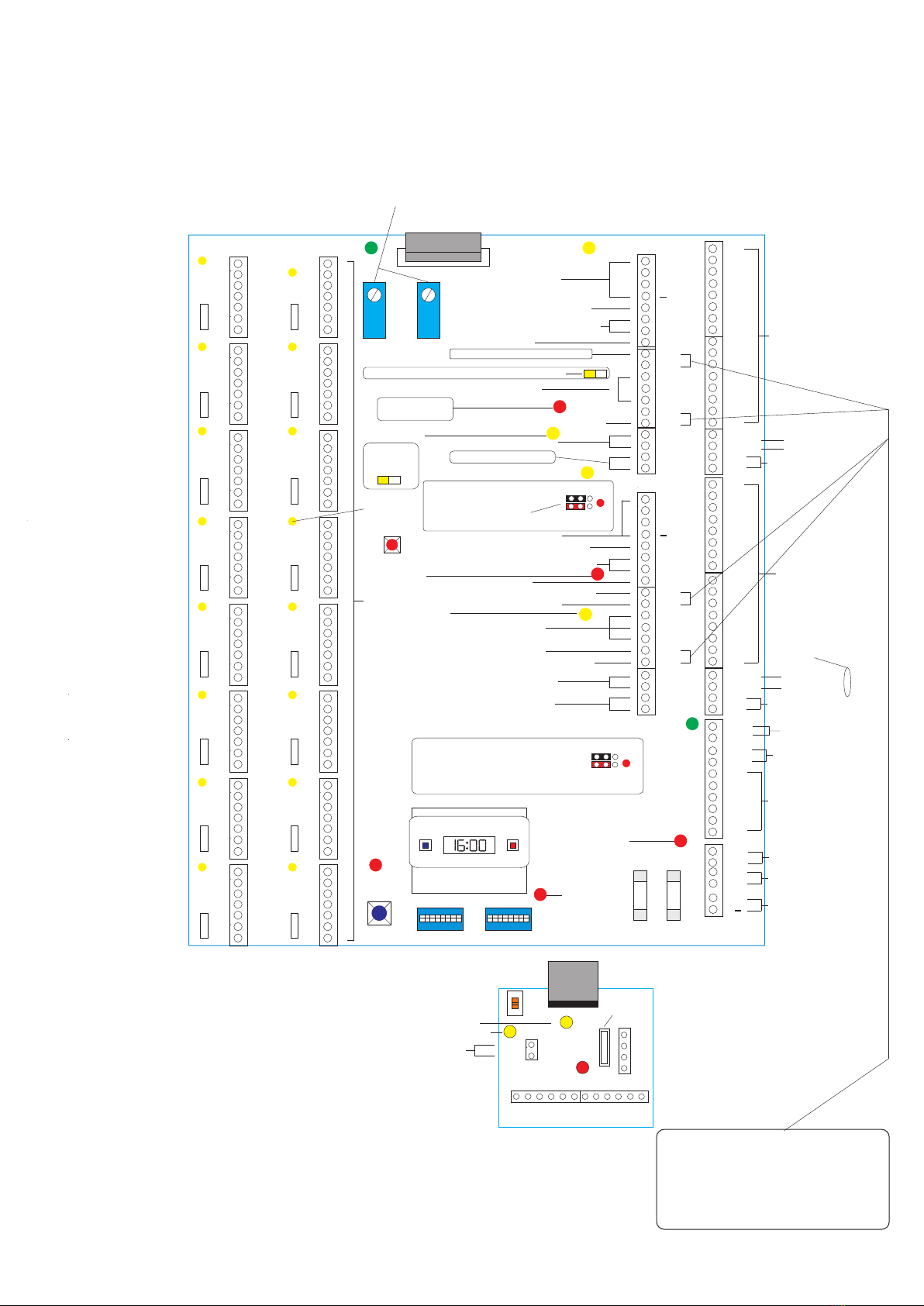
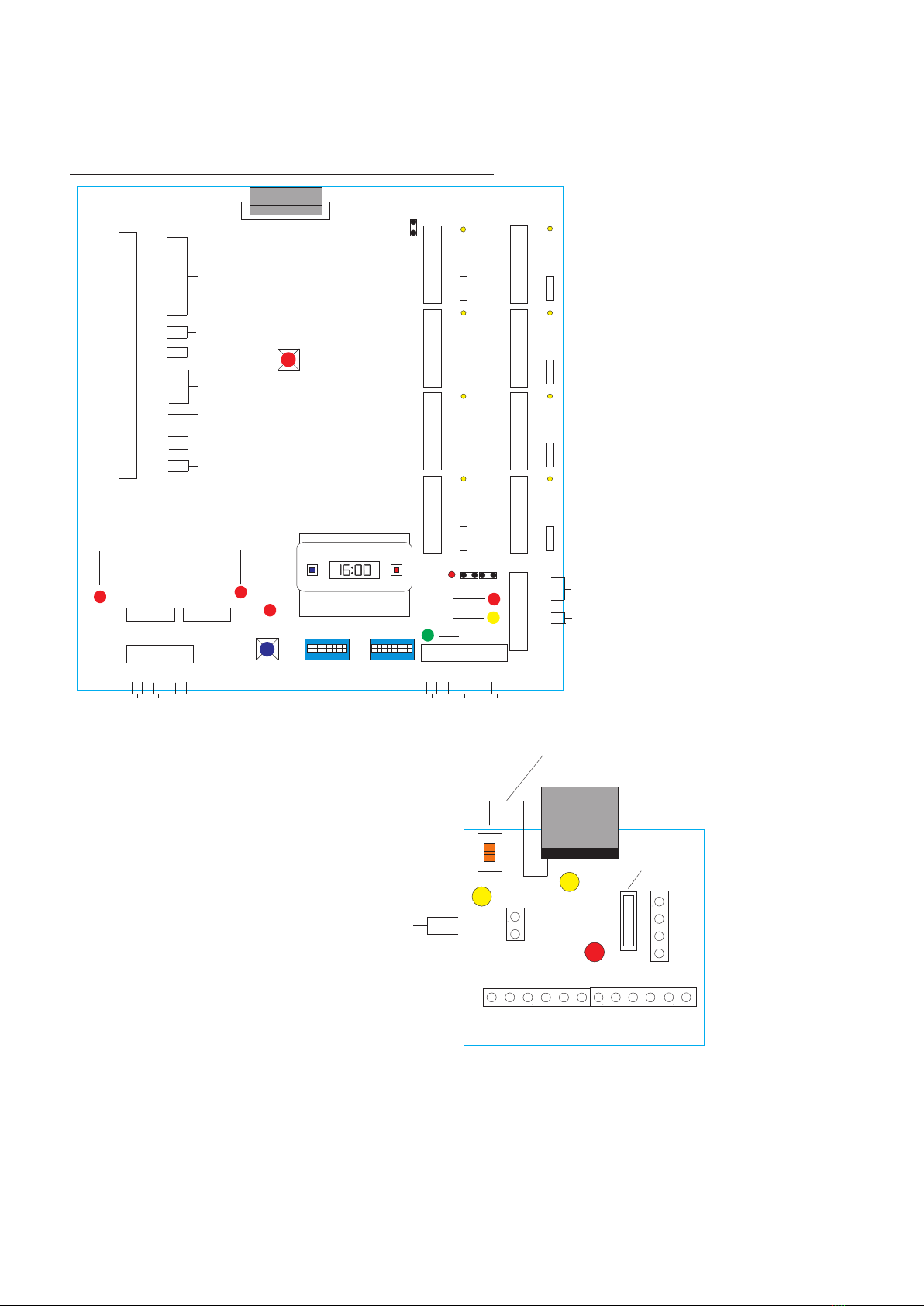
8 & 16 way Main & Riser Controller Overview
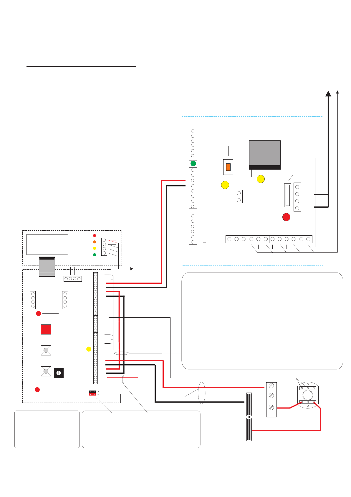
Single Entrance With PAC and Landing Control
Single Entrance With PAC
Contents
Page
DIGITAL SYSTEM:
3
4
1
5-5A
6
7
8
9
13
14
10-12
15
16
17
18
18A
19
20
21
22
23
24
Sounder (Hard of Hearing)
Strobe (Hard of Hearing)
Single & Dual Landing Panel
Panel Amplifier
AT-PID SelectLine Telephone (Full Facility)
Auxiliary BST/GMT Clock Programming
On Board Digital Clock Programming
Controller Switch Settings (Example)
Controller Switch Settings
Controller Programming Instructions
System Connection Summary
Digital PAC 1000, 1000N, 2100/2200 Controller & Reader
Functional PAC Easikey 99, 1000/2100/2200 Controllers & Reader
AC Fail Secure Lock Release
DC Fail Safe Lock Release
DC Fail Secure Lock Release
Line Buffer
External Trades Clock (BST/GMT)
12VDC Auxiliary Output (Max 1Amp Output)
Request To Exit & Fire Override (Fail Safe Lock Release)
Fire Override Switch (Failsafe & Fail Secure)
Commissioning/Final Inspection Form
Telephone Tenant Instruction Leaflet
System Controller Default Settings
Power Specification
System Wiring Colour Codes 25-26
27
28
29
Digital Audio
Installation Manual

Digital
Audio
Systems
- 2 -
Digital Audio
Installation Manual
Digital Audio
Revision 1.09 Date: 05/12/2011

Digital System Basic Overview
Telephone Handset
Strobe/Sounder
PANEL1
PANEL2
3
4
5
6
7
8
9
10
11
12
13
14
15
16
1
2
3
4
5
6
7
8
9
10
11
12
13
14
15
16
1
2
1
1,C
2
6
9
PS
PL
DL
1,C
2
6
9
PS
PL
DL
1,C
2
6
9
PS
PL
DL
1,C
2
6
9
PS
PL
DL
1,C
2
6
9
PS
PL
DL
1,C
2
6
9
PS
PL
DL
1,C
2
6
9
PS
PL
DL
1,C
2
6
9
PS
PL
DL
1,C
2
6
9
PS
PL
DL
1,C
2
6
9
PS
PL
DL
1,C
2
6
9
PS
PL
DL
1,C
2
6
9
PS
PL
DL
1,C
2
6
9
PS
PL
DL
1,C
2
6
9
PS
PL
DL
1,C
2
6
9
PS
PL
DL
1,C
2
6
9
PS
PL
DL
CC
DML
SBL
RTE
RTE
FS
FS
SA
SE
LC
LAC
LAC
RTE T
PAC
DMS
TR
2
+
--
Tx
Rx
OV
OV
OV
OV
TX
TX
B+
B--
ENTER FUNCTION
Riser/Landing Controller
DATA
TC
TC
12V
12V
12V
1
CC
DML
SBL
RTE
RTE
FS
FS
SA
SE
LC
LAC
LAC
RTE T
PAC
DMS
TR
2
+
--
LINE 9
LINE 1 LINE 2
LINE 10
LINE 3
LINE 11
LINE 4
LINE 12
LINE 5
LINE 13
LINE 6
LINE 14
LINE 7
LINE 15
LINE 8
LINE 16
RESET
A+D+H
D
C
Battery
2 Amp Fuses
Telephone Handset
A+D+H
Digital Interface
Strobe/Sounder
C
A -Single Earth 2.5mm Mains Type Cable (Continuity)
Cable Requirements
B - 2 Wire (1 Pair) 1mm Mains Type Cable (Lock Release)
D - 8 Wire (4 Pair) CW1308 0.5mm dia Multipair Cable (Minimum)
C - 2 Wire (1 Pair) CW1308 0.5mm dia Multipair Cable (Minimum)
H - 2 Wire (1 Pair) 2.5mm Mains Type Cable (50V Power Rail)
PANEL 1
PANEL 2
3
4
5
6
7
8
9
10
11
12
13
14
15
16
1
2
3
4
5
6
7
8
9
10
11
12
13
14
15
16
1
2
1
1,C
2
6
9
PS
PL
DL
1,C
2
6
9
PS
PL
DL
1,C
2
6
9
PS
PL
DL
1,C
2
6
9
PS
PL
DL
1,C
2
6
9
PS
PL
DL
1,C
2
6
9
PS
PL
DL
1,C
2
6
9
PS
PL
DL
1,C
2
6
9
PS
PL
DL
1,C
2
6
9
PS
PL
DL
1,C
2
6
9
PS
PL
DL
1,C
2
6
9
PS
PL
DL
1,C
2
6
9
PS
PL
DL
1,C
2
6
9
PS
PL
DL
1,C
2
6
9
PS
PL
DL
1,C
2
6
9
PS
PL
DL
1,C
2
6
9
PS
PL
DL
CC
DML
SBL
RTE
RTE
FS
FS
SA
SE
LC
LAC
LAC
RTE T
PAC
DMS
TR
2
+
--
Tx
Rx
OV
OV
OV
OV
TX
TX
B+
B--
ENTER FUNCTION
Main Controller
DATA
TC
TC
12V
12V
12V
1
CC
DML
SBL
RTE
RTE
FS
FS
SA
SE
LC
LAC
LAC
RTE T
PAC
DMS
TR
2
+
--
LINE 9
LINE 1 LINE 2
LINE 10
LINE 3
LINE 11
LINE 4
LINE 12
LINE 5
LINE 13
LINE 6
LINE 14
LINE 7
LINE 15
LINE 8
LINE 16
RESET
D
Fused Spur
Digital Interface
Battery
2 Amp Fuses A+B+D
- 3-
Digital Audio
Installation Manual
D
TRADES
Digital Audio
Magnetic Locks
with Door Contact
To PAC
Controller
A+B+C
Emergency
Override
Emergency
Override
A+B+C
PUSH
TO EXIT
B+C
Revision 1.09 Date: 05/12/2011

Digital System with Landing Controller Overview
A -Single Earth 2.5mm Mains Type Cable (Continuity)
Cable Requirements
B - 2 Wire (1 Pair) 1mm Mains Type Cable (Lock Release)
D - 8 Wire (4 Pair) CW1308 0.5mm dia Multipair Cable (Minimum)
E - 20 Wire (10 Pair) CW1308 0.5mm dia Multipair Cable (Minimum)
F - 30 Wire (15 Pair) CW1308 0.5mm dia Multipair Cable (Minimum)
C - 2 Wire (1 Pair) CW1308 0.5mm dia Multipair Cable (Minimum)
H - 2 Wire (1 Pair) 2.5mm Mains Type Cable (50V Power Rail)
Telephone Handset
Strobe/Sounder
PANEL1
PANEL2
3
4
5
6
7
8
9
10
11
12
13
14
15
16
1
2
3
4
5
6
7
8
9
10
11
12
13
14
15
16
1
2
1
1,C
2
6
9
PS
PL
DL
1,C
2
6
9
PS
PL
DL
1,C
2
6
9
PS
PL
DL
1,C
2
6
9
PS
PL
DL
1,C
2
6
9
PS
PL
DL
1,C
2
6
9
PS
PL
DL
1,C
2
6
9
PS
PL
DL
1,C
2
6
9
PS
PL
DL
1,C
2
6
9
PS
PL
DL
1,C
2
6
9
PS
PL
DL
1,C
2
6
9
PS
PL
DL
1,C
2
6
9
PS
PL
DL
1,C
2
6
9
PS
PL
DL
1,C
2
6
9
PS
PL
DL
1,C
2
6
9
PS
PL
DL
1,C
2
6
9
PS
PL
DL
CC
DML
SBL
RTE
RTE
FS
FS
SA
SE
LC
LAC
LAC
RTE T
PAC
DMS
TR
2
+
--
Tx
Rx
OV
OV
OV
OV
TX
TX
B+
B--
ENTER FUNCTION
Riser/Landing Controller
DATA
TC
TC
12V
12V
12V
1
CC
DML
SBL
RTE
RTE
FS
FS
SA
SE
LC
LAC
LAC
RTE T
PAC
DMS
TR
2
+
--
LINE 9
LINE 1 LINE 2
LINE 10
LINE 3
LINE 11
LINE 4
LINE 12
LINE 5
LINE 13
LINE 6
LINE 14
LINE 7
LINE 15
LINE 8
LINE 16
RESET
A+D+H
D
C
Battery
2 Amp Fuses
Telephone Handset
A+D+H
Digital Interface
Strobe/Sounder
C
PANEL1
PANEL2
3
4
5
6
7
8
9
10
11
12
13
14
15
16
1
2
3
4
5
6
7
8
9
10
11
12
13
14
15
16
1
2
1
1,C
2
6
9
PS
PL
DL
1,C
2
6
9
PS
PL
DL
1,C
2
6
9
PS
PL
DL
1,C
2
6
9
PS
PL
DL
1,C
2
6
9
PS
PL
DL
1,C
2
6
9
PS
PL
DL
1,C
2
6
9
PS
PL
DL
1,C
2
6
9
PS
PL
DL
1,C
2
6
9
PS
PL
DL
1,C
2
6
9
PS
PL
DL
1,C
2
6
9
PS
PL
DL
1,C
2
6
9
PS
PL
DL
1,C
2
6
9
PS
PL
DL
1,C
2
6
9
PS
PL
DL
1,C
2
6
9
PS
PL
DL
1,C
2
6
9
PS
PL
DL
CC
DML
SBL
RTE
RTE
FS
FS
SA
SE
LC
LAC
LAC
RTE T
PAC
DMS
TR
2
+
--
Tx
Rx
OV
OV
OV
OV
TX
TX
B+
B--
ENTER FUNCTION
Main Controller
DATA
TC
TC
12V
12V
12V
1
CC
DML
SBL
RTE
RTE
FS
FS
SA
SE
LC
LAC
LAC
RTE T
PAC
DMS
TR
2
+
--
LINE 9
LINE 1 LINE 2
LINE 10
LINE 3
LINE 11
LINE 4
LINE 12
LINE 5
LINE 13
LINE 6
LINE 14
LINE 7
LINE 15
LINE 8
LINE 16
RESET
D
Fused Spur
Digital Interface
Battery
2 Amp Fuses
A+B+D
- 4 -
Digital Audio
Installation Manual
Emergency
Override
Emergency
Override
PUSH
TO EXIT
A+B+C
PUSH
TO EXIT
A+B+F
Landing Panel
TRADES
A+B+C
TRADES
Magnetic Locks
with Door Contact
B+C
Emergency
Override
Emergency
Override
PUSH
TO EXIT
A+B+C
PUSH
TO EXIT
A+B+F
Landing Panel
TRADES
A+B+C
TRADES
Magnetic Locks
with Door Contact
B+C
D
TRADES
Digital Audio
To PAC
Controller
A+B+C
Emergency
Override
Emergency
Override
A+B+C
PUSH
TO EXIT
B+C
Revision 1.09 Date: 05/12/2011

- 4A -
Digital Audio
Installation Manual
230VAC to 50VAC Supply
Fused Spur
50VAC Rail
to a Controller
Digital 50VAC Main Power Supply Overview
AC2
5Amp Fuse
AC1
Digital Audio
Revision 1.09 Date: 05/12/2011

16 way Main, Riser and Landing Controller Overview
Digital Audio
Installation Manual
Factory fitted LINK when a BST/GMT landing
trade clock is required
AC1
TXP
TXP
50Vac Riser Output
Fuse 3.15A
Anti surge
50VAC Supply Indicator
Data Status Indicator
Speech Active Indicator
50VAC 50Vac Riser Input
50Vac Riser Output
50Vac Riser Input
AC1
AC2
AC2
CTS
OV
OV
TC
TC
CTS
Data Select
BST/GMT Output
BST/GMT Input
Data Select
Data Output
Data Input
Mic Output
Speaker Output
Speaker Input
0V Output
0V Input
Mic Input
SD
SD
2
2
1
1
1,C
2
6
9
PS
PL
DL
1,C
2
6
9
PS
PL
DL
1,C
2
6
9
PS
PL
DL
1,C
2
6
9
PS
PL
DL
1,C
2
6
9
PS
PL
DL
1,C
2
6
9
PS
PL
DL
1,C
2
6
9
PS
PL
DL
1,C
2
6
9
PS
PL
DL
1,C
2
6
9
PS
PL
DL
1,C
2
6
9
PS
PL
DL
1,C
2
6
9
PS
PL
DL
1,C
2
6
9
PS
PL
DL
1,C
2
6
9
PS
PL
DL
1,C
2
6
9
PS
PL
DL
1,C
2
6
9
PS
PL
DL ENTER
Data Enter
Button
& Indicator
FUNCTION
Function Switch Data Switch
Digital Time Clock
DATA
LINE 2
LINE 1
LINE 4
LINE 5
LINE 6
LINE 7
LINE 8
LINE 9
LINE 10
LINE 11
LINE 12
LINE 13
LINE 14
LINE 15
LINE 16
1,C
2
6
9
PS
PL
DL
LINE 3
RESET
System Reset
Button
16 Apartment Inputs
Flat Called Indicator
Entrance Panel 1 Amplifier
Entrance Panel 1 Button Common
Entrance Panel 1 Busy & Enter Display
DC Lock Power
Healthy Indicator
Lock Released
Indicator
Call Indicator
Lock Released
Indicator
DC Lock Power
Healthy Indicator
12V DC Lock Release
Output ( N/O & N/C )
Request to Exit ( Timed )
Door Monitoring Switch
Request to Exit ( Timed )
Door Monitoring Switch
Entrance Panel 2 Amplifier
Entrance Panel 2 Button Common
Entrance Panel 2 Busy/Enter Display
12V DC Lock Release
Outputs ( N/O & N/C )
5 Amp Fuses
System Supply
Indicator
Auxilliary Supply
Indicator
0V
0V
0V
MFL+
MF
MFL-
12V
12V
12V
Mains Fail Output to Door LED
3 x 12 VDC Auxilliary
Power Outputs
B+
B
TX
TX
AC Power Input
from LV Transformer
TC+
TC-
Secondary Trades
Clock input
Mains Fail Indicator
Backup Battery
Input
ON
1 2 3 4 5 6 7 8
ON
1 2 3 4 5 6 7 8
PANEL 1
3
4
5
6
7
8
9
10
11
12
13
14
15
16
1
2
1
CC
DML
SBL
LS+
FCL
LS1
LS2
SA
SE
LC
LS -
2
+
Entrance Panel 1
Buttons
RTE/T
RTE/T
RTE/T
RTE/T
DMS
DMS
DMS
DMS
PAC1+ PAC Entrance 1 Input
PAC1 - PAC Entrance 1 Input
TR
TR Trades Button
0
PANEL 2
3
4
5
6
7
8
9
10
11
12
13
14
15
16
1
2
1
CC
DML
SBL
LS+
FCL
LS1
LS2
SA
SE
LC
LS-
2
+
Entrance Panel 2
Buttons
PAC2+ PAC Entrance 2 Input
PAC2 - PAC Entrance 2 Input
TR
TR Trades Button
0
PAC Jumpers
See page 18
PAC Jumpers
See page 18
Telephone Door open Tone ON/OFF Default OFF
Lock Supply + Input (12V-24VAC/DC
Lock Supply - Input (12V-24VAC/DC
Lock Supply + Input (12V-24VAC/DC
Lock Supply - Input (12V-24VAC/DC
Note:
Fitted Links will give a
12VDC Lock output. With the Links
removed a seperate 12VDC/AC
-24VDC/AC Lock Power Supply can
be connected to LS1(+) and LS2 ( - )
- 5 -
Digital Audio
Revision 1.09 Date: 05/12/2011

Mains Fail Output
to Door LED
3 x 12 VDC Auxilliary
Power Outputs
TX
TX
AC Power Input
from LV Transformer
Secondary Trades
Clock input
Mains Fail Indicator
Video Control (Pre wired)
Backup Battery
Input
PAC Entrance 2 Input
TR
TR Trades Button
RESET
System Reset
Button
16 Apartment Inputs
Flat Called Indicator
Entrance Panel 1 Amplifier
Entrance Panel 1 Button Common
Entrance Panel 1 Busy & Enter Display
DC Lock Power
Healthy Indicator
Lock Released
Indicator
Call Indicator
Lock Released
Indicator
DC Lock Power
Healthy Indicator
12V DC Lock Release Output ( N/O & N/C )
Request to Exit ( Timed )
Door Monitoring Switch
Entrance Panel 2 Button Common
Entrance Panel 2 Busy/Enter Display
12V DC Lock Release
Outputs ( N/O & N/C )
5 Amp Fuses
System Supply
Indicator
Auxilliary Supply
Indicator
Panel Amplifier Active
0V
0V
0V
MFL+
VC2
VC1
MFL-
12V
12V
12V
B+
B
TC+
TC-
FUNCTION
Function Switch Data Switch
DATA
ON
1 2 3 4 5 6 7 8
ON
1 2 3 4 5 6 7 8
PANEL 1
1
CC
DML
SBL
LS+
FCL
LS1
LS2
SA
SE
LC
LS -
2
+
RTE/T
RTE/T
RTE/T
RTE/T
DMS
DMS
DMS
DMS
Sub Entrance
Panel 1 Buttons
TR
TR Trades Button
3
4
5
6
7
8
9
10
11
12
13
14
15
16
1
2
PAC1+
PAC1 -
PAC Entrance 1 Input
0
PANEL 2
1
CC
DML
SBL
LS+
FCL
LS1
LS2
SA
SE
LC
LS-
2
+
PAC2+
PAC2 -
0
Telephone Door Release Tone ON/OFF Default OFF
Lock Supply + Input (12V-24VAC/DC
Lock Supply - Input (12V-24VAC/DC
Lock Supply + Input (12V-24VAC/DC
Lock Supply - Input (12V-24VAC/DC
Sub Entrance
Panel 2 Buttons
3
4
5
6
7
8
1
2
9
10
11
12
13
14
15
16
1,C
2
6
9
PS
PL
DL
1,C
2
6
9
PS
PL
DL
1,C
2
6
9
PS
PL
DL
1,C
2
6
9
PS
PL
DL
1,C
2
6
9
PS
PL
DL
1,C
2
6
9
PS
PL
DL
1,C
2
6
9
PS
PL
DL
1,C
2
6
9
PS
PL
DL
1,C
2
6
9
PS
PL
DL
1,C
2
6
9
PS
PL
DL
1,C
2
6
9
PS
PL
DL
1,C
2
6
9
PS
PL
DL
1,C
2
6
9
PS
PL
DL
1,C
2
6
9
PS
PL
DL
1,C
2
6
9
PS
PL
DL
LINE 2
LINE 1
LINE 4
LINE 5
LINE 6
LINE 7
LINE 8
LINE 9
LINE 10
LINE 11
LINE 12
LINE 13
LINE 14
LINE 15
LINE 16
1,C
2
6
9
PS
PL
DL
LINE 3
ENTER
Data Enter
Button
& Indicator
BST/GMT Output
BST/GMT Input
Speaker Output
Speaker Input
AC1
TXP
TXP
50Vac Riser Output
Fuse 3.15A
Anti surge
50VAC Supply Indicator
Data Status Indicator
Speech Active Indicator
50VAC 50Vac Riser Input
50Vac Riser Output
50Vac Riser Input
AC1
AC2
AC2
CTS
OV
OV
TC
TC
CTS
Data Select
Data Select
Data Output
Data Input
Mic Output
0V Output
0V Input
Mic Input
SD
SD
2
2
1
1
Note:
Fitted Links will give a
12VDC Lock output. With the Links
removed a seperate 12VDC/AC
-24VDC/AC Lock Power Supply can
be connected to LS1(+) and LS2 ( - )
TIME CLOCK
SML2000-3
Doors
Lock Release Tone and
Door Open Tone Adjustment
1 2
1 & 2 ON No PAC connected
2 & 3 ON PAC connected
(RED & BLACK must
BOTH be moved).
12 3
12 3
Entrance Panel 2 Amplifier
12VDC Lock Release from
PAC Controller to be
programmed to 2 seconds
Fail Safe.
Door Open Indicator
Progressive
Ring Tone
Default ON
Door Monitoring Switch
PAC Jumpers
1 & 2 ON No PAC connected
2 & 3 ON PAC connected
(RED & BLACK must BOTH be moved).
12 3
12 3
- 5A -
Digital Audio
Revision 1.09 Date: 05/12/2011

Digital Audio
Installation Manual
12VDC Lock Release
Output (N/o & N/C)
12VAC Lock Release
Output
8 Flat Inputs
8 way Riser/LandingController
1,C
2
6
9
PS
PL
DL
LINE 2
1,C
2
6
9
PS
PL
DL
LINE 1
1,C
2
6
9
PS
PL
DL
LINE 8
1,C
2
6
9
PS
PL
DL
LINE 4
1,C
2
6
9
PS
PL
DL
LINE 3
1,C
2
6
9
PS
PL
DL
LINE 6
5 Amp Fuses
LS+
LS-
LS1
LS2
SA
SE
LC
1,C
2
6
9
PS
PL
DL
LINE 7
1,C
2
6
9
PS
PL
DL
LINE 5
FUNCTION
Function Switch Data Switch
Digital Time Clock
DATA
ENTER
Data Enter
Button
Soft Reset
Button
ON
1 2 3 4 5 6 7 8
ON
1 2 3 4 5 6 7 8
CALL
3
4
5
6
7
8
PAC+
PAC-
TR
1
2
Entrance Panel Buttons
Optional Earpiece Tone
on Lock Release
12VDC 2 second FAILSAFE PAC Input
Trades Button
FCL
RTE/T
Entrance Panel Button Common
Entrance Panel Amplifier
Door Open Indicator Display &
System Busy Indicator Display
Request to Exit ( Timed )
TR
1
2
+
0 -
CC
DML
SBL
RTE/T
AC Lock Power
Indicator
Mains Fail
Indicator
DC Lock Power
Indicator
MFL
MFL
Mains Fail Indicator
Door Monitoring
Contacts
2 x 12VDC Auxilliary
Power Outputs
Total 3Amp
12V
0V
12V
0V
DMS
DMS
B-
B+
Battery Back Up Input
Secondary Clock Input
AC Power Input from LV
Transformer
TX
TX
TC
TC
System Supply
Indicator
Auxilliary Supply
Indicator
AC1
TXP
TXP
50Vac Riser Output
Fuse 3.15A
Anti surge
50VAC Supply Indicator
Data Status Indicator
Speech Active Indicator
50VAC
Factory fitted LINK when a
BST/GMT landingtrade clock
is required
50Vac Riser Input
50Vac Riser Output
50Vac Riser Input
AC1
AC2
AC2
CTS
OV
OV
TC
TC
CTS
Data Select
BST/GMT Output
BST/GMT Input
Data Select
Data Output
Data Input
Mic Output
Speaker Output
Speaker Input
0V Output
0V Input
Mic Input
SD
SD
2
2
1
1
- 6 -
8 way Main, Riser and Landing Controller Overview
Digital Audio
Revision 1.09 Date: 05/12/2011

- 7 -
Digital Network & Power Overview
Digital Audio
Installation Manual
Pre-wired
To Panel Amplifier
+
_
1
2
Display
BUSY
FLAT CALLED
TALK NOW
ENTER
Note:
See page 24-25 for PAC connections and
jumper positions.
1
2
+VE
-VE
12V
12V
0V
pcb. 2024
Iss. 3
With DDA
facility
Vout
0V
SCN
Flat Programming
Button
Board Healthy
Indicator
12V
0V
SCN
SIG
CAM2 (Lobby)
12V
0V
SCN
SIG
CAM1(Panel)
+
_
1
2
RTE/T
LS2
PAC +
PAC -
LS1
LC
SA
SE
Stb-
Stb+
0V
CTS
SD
DMS
DMS
RTE/T
AC1
TXP
TXP
Fuse 3.15A
Anti surge
50VAC Supply Indicator
Digital Interface Board
AC1
AC2
AC2
CTS
OV
OV
TC
TC
CTS
SD
SD
2
2
1
1
Main Controller
Next Riser
Controller
0V
0V
0V
MFL+
MF
MFL-
12V
12V
12V
B+
B
TX
TX
TC+
TC-
15
16
PAC2+
PAC2 -
TR
TR
Note:
Pre-wired for 12VDC Lock Output.
If a 12VAC/DC Lock Output is required use LS1& LS2
with a secondary power Supply.
If a Volt free contact is required to trigger a PAC Controller
RTE then remove both links and use LS1 & SA for Normally
Closed and LS1 & SE for Normally Open.
This will give Volt free contacts when a Lock release is
initiated from the Telephone/Monitor or system RTE is
pressed
For Fail Secure (SE)
Lock Releases
wire N/O to RTE/T only.
Common
1
Normally
Open
4
Normally
Closed
2
RTE
N/C
N/O
Magnetic Locks
with Door Contact
Emergency Override Switch
B+C
12VDC Lock Release Output from PAC
Controller programmed to 2 seconds
Fail Safe.
If the above is required please move
both jumpers to connect pins 2 & 3
Sw1
Prog
Sw2
Up
Load
Sw3
Down
Load
Digital Entrance Panel
Door Open
Tone Control
PAC relay
Healthy Indicator
1 2 3
1 2 3
1 & 2 Jumper positions
NO PAC connected
2 & 3 Jumper positions
PAC connected
Digital Audio
Revision 1.09 Date: 05/12/2011

Landing Entrance Panel wiring detail
Digital Entrance Panel wiring detail
Main/Riser Controller
Network Interface
Door Alarm Strobe/Sounder
Request To Exit/
Fire Override Switch
Door Open
12VDC/AC Fail Secure Lock Output
+12-24VDC/AC Lock Input Supply
-12-24VDC/AC Lock Input Supply
12VDC/AC Fail Safe Lock Output
12VDC/AC Lock Common Output
Entrance Panel Video Output
- 8 -
Digital Audio
Installation Manual
12V
12V
12V
0V
0V
0V
3 x 12VDC Auxiliary
Power Outputs 3Amp
overall output
Pre-wired
To Panel Amplifier
Emergency Override Switch
For Fail Safe (SA) Lock Releases.
Common
1
Normally
Open
4
Normally
Closed
2
RTE
N/C
N/O
SA
LC
1
2
+VE
-VE
12V
12V
0V
Sw1
Prog
Sw2
Up
Load
Sw3
Down
Load
LS2
PAC+
LS1
LC
SA
SE
Stb-
Stb+
0V
CTS
SD
DMS
DMS
RTE/T
RTE/T
Vout
0V
SCN
Flat Programming
Button
+
_
1
2
12V
0V
SCN
SIG
CAM2 (Lobby)
12V
0V
SCN
SIG
CAM1(Panel)
+
_
1
2
Display
BUSY
FLAT CALLED
TALK NOW
ENTER
Board Healthy
Indicator
Door Open
Tone Control
pcb.2024
Iss.3
With DDA
requirements
PAC-
Digital Entrance Panel
PAC relay
Healthy Indicator
1 2 3
1 2 3
PANEL 1
3
4
5
6
7
8
9
10
11
12
13
14
15
16
1
2
Brown of White
White of Brown
Slate of White
White of Slate
Red of Orange
Orange of Red
Green of Red
Red of Green
Brown of Red
Red of Brown
Black of Blue
Blue of Black
Black of Orange
Orange of Black
Green of Black
Black of Green
Blue of White
White of Blue
Blue of Red
White of Orange and Orange of White
Slate of Red and Red of Slate
Black of Slate
Slate of Black
Red of Blue
1
CC
DML
SBL
FCL
2
+
FCL
DML
SBL
1
+
-
Black of Brown
Brown of Black
TR
TR
0
0
BUSY
FLAT CALLED
TALK NOW
ENTER
Note:
See page 15 for
wiring detail
Note:
See Amplifier detail
Page 15
Magnetic Locks
with Door Contact
Digital Audio
Panel Amplifier
To
Controller
-
+
1
2
Intercall
Functional
Revision 1.09 Date: 05/12/2011

Digital Audio
Installation Manual
- 8A -
Digital Entrance Panel
Pre-wired
To Panel Amplifier
Main Controller
0V
0V
12V
12V
C
W
W
W
W
O
O
O
O
Aux1In
Aux2In
Aux3In
Aux4In
Aud1
Aud1
Aud2
Aud2
V Out
A1 OutA2OutA3OutA4Out
V in
V in
C
C
C
CTS
12V
0V
CTS
12V
0V
12V
12V
N/O - N/C Auxiliary Output 1
N/O - N/C Auxiliary Output 2
N/O - N/C Auxiliary Output 3
N/O - N/C Auxiliary Output 4
Audio Microphone Transmission
Hard Wired
Input Switches
Audio Speaker Transmission
Video Input from Digital Panel
Video Output to Concierge
Auxiliary Input 1
Auxiliary Input 2
Auxiliary Input 3
Auxiliary Input 4
Switched via
the Data Line
0V
V Out
1
2
SD
0V
1
2
SD
0V
0V
S1
S2
L1
L2
A0
01
A2
12VDC Supply from 12VDC
ControllerAuxiliary
Auxiliary Output
On/Off
Remote Speech
Adjustment
SML-2036
Building Interface card
A
G
R
T
RS232
D
C
B
RS475
RS232 Transmission Input/Output
RS485 Transmission Input/Output
Concierge Building Interface Card (Multi-Building) wiring detail
Controller 2
Interface
Card
AC1
TXP
TXP
Fuse 3.15A
Anti surge
50VAC Supply Indicator
AC1
AC2
AC2
CTS
OV
OV
TC
TC
CTS
SD
SD
2
2
1
1
Controller 2
Interface
Card
AC1
TXP
TXP
Fuse 3.15A
Anti surge
50VAC Supply Indicator
AC1
AC2
AC2
CTS
OV
OV
TC
TC
CTS
SD
SD
2
2
1
1
+
_
1
2
BUSY
CONCIERGE
CALLED
TALK NOW
ENTER
+
_
1
2
1
2
+VE
-VE
12V
12V
0V
Sw1
Prog
Sw2
Up
Load
Sw3
Down
Load
LS2
PAC+
PAC-
LS1
LC
SA
SE
Stb-
Stb+
0V
CTS
SD
DMS
DMS
RTE/T
RTE/T
Vout
0V
SCN
Flat Programming
Button
Board Healthy
Indicator
12V
0V
SCN
SIG
CAM2 (Lobby)
12V
0V
SCN
SIG
CAM1(Panel)
Telephone
Audio to and
from Concierge
DIGITAL PANEL
INTERFACE
Digital Entrance Panel
PAC relay
Healthy Indicator
1 2 3
1 2 3
Door Open
Tone Control
Digital Audio
Revision 1.09 Date: 05/12/2011

Digital System Flat Programming Form
Note:
Remember to PRESS the Enter button
after setting Dill switches positions.
- 9 -
1 3 4 5 6 7 82 1 3 4 5 6 7 82
1 3 4 5 6 7 82 1 3 4 5 6 7 82 1 3 4 5 6 7 82 1 3 4 5 6 7 82 1 3 4 5 6 7 82
1 3 4 5 6 7 82 1 3 4 5 6 7 82 1 3 4 5 6 7 82
FUNCTION SWITCH
1 13 34 45 56 67 78 82 2
DATA SWITCH DATA SWITCH
Controller ControllerControllerControllerController
1 3 4 5 6 7 82
DATA SWITCH
1 3 4 5 6 7 82
DATA SWITCH
1 3 4 5 6 7 82
DATA SWITCH
FUNCTION SWITCH FUNCTION SWITCH FUNCTION SWITCH FUNCTION SWITCH
1 2 3 4 5
FUNCTION SWITCH
1 13 34 45 56 67 78 82 2
DATA SWITCH DATA SWITCH
Controller ControllerControllerControllerController
13 4 5 6 7 82
DATA SWITCH
1 3 4 5 6 7 82
DATA SWITCH
1 3 4 5 6 7 82
DATA SWITCH
FUNCTION SWITCH FUNCTION SWITCH FUNCTION SWITCH FUNCTION SWITCH
6 7 8 9 10
ON
ON
ON
ON
Digital Audio
Installation Manual
Line No. Flat Number
1
2
3
4
5
6
7
8
9
10
11
12
13
14
15
16
Flat Number Flat Number Flat Number Flat Number
Line No. Flat Number
1
2
3
4
5
6
7
8
9
10
11
12
13
14
15
16
Flat Number Flat Number Flat Number Flat Number
Digital Audio
Revision 1.09 Date: 05/12/2011

Digital Entrance Panel Programming Instructions
System Function Programming
- 10 -
Digital Audio
Installation Manual
Function 1 (Lock Release)
Press 1 on the Digital Panel keypad and then press the PROG button.
Enter between 1 and 255 seconds and press CALL.
This will set the Lock Release duration time for that Panel.
Function 2 (Door Open Alarm Duration)
Press 2 on the Digital Panel keypad and then press the PROG button.
Enter between 1 and 255 minutes and press CALL.
This will set the Door Alarm Duration time.
Function 3 (Door Open Alarm Delay)
Press 3 on the Digital Panel keypad and then press the PROG button.
Enter between 1 and 255 minutes and press CALL.
This will set the Door Alarm Delay time.
Function 4 (Service Access Code)
Press 4 on the Digital Panel keypad and then press the PROG button.
Enter up to 5 digits and press CALL.This will establish a Service Access Code.
If a 5 digit service code has already been entered the Digital Panel will display AC?
alternating with the remaining 4 numbers, i.e. AC1 - 2345.
This can, if required be deleted by pressing the CANCEL button.
Press the TRADES button, Enter Code and then press Trades or Call to release the Door.
Function 5 (Engineering Access Code)
Press 5 on the Digital Panel keypad and then press the PROG button.
Enter up to 5 digits and press CALL.This will establish an Engineering Access Code.
If a 5 digit engineering code has already been entered the Digital Panel will display
EA1 alternating with the remaining 4 numbers, i.e. EA1 - 2345.
This can, if required be deleted by pressing the CANCEL button.
Press the TRADES button, Enter Code and then press Trades or Call to release the Door.
Function Description Parameters Notes
1 Lock Release Time 1 - 255 Seconds
2
Door Alarm Delay Time
1 - 255 Minutes
10
27
Panel Facility Configuration
Erase All Memory and Reset -
9 Communication Test facility - Controller Interface Data Continuity Test
90 Second Erase on a 30 count will automatically re-set the default values
Alpha Numeric, Cameras, Concierge and Door Tone On/Off
8 Set Digital Panel Number 1 - 9
A F
7 Call Duration Time 1 - 255 Seconds
6 Monitor Ring Time 1 - 255 Seconds
5 Engineers Access Code (EA) 1 - 5 Digits Code + Trades to release door
4 Service Access Code (AC) 1 - 5 Digits Code + Trades to release door
3
Door Open Duration Time
1 - 255 Minutes Zero minutes will disable the Door Alarm
Function 6 (Telephone Ring Time)
Press 6 on the Digital Panel keypad and then press the PROG button.
Enter between 1 and 255 seconds and press CALL.
This can if required be deleted by using the CANCEL button.
This will set the Digital Panel to Telephoner ring time.
Function 7 (Call Duration Time)
Press 7 on the Digital Panel keypad and then press the PROG button.
Enter between 1 and 255 seconds and press CALL.
This can if required be deleted by using the CANCEL button.
This will set the Digital Panel to Telephone Call Duration time.
Digital Audio
Revision 1.09 Date: 05/12/2011

- 11 -
Digital Audio
Installation Manual
Digital Entrance Panel Programming Instructions cont...
System Function Programming cont...
Function 8 (Setting Digital Panel Number(s))
Press 8 on the Digital Panel keypad and then press the PROG button.
Enter from 1 to a maximum of 8 depending on the position of the Digital Panel in the system
and press CALL.
If required a set Panel position can be deleted by using the CANCEL button.
This will set the Digital Panel position in a Single or Multi Entrance system.
Function 9 (Data Communication Test Facility)
Press 9 on the Digital Panel keypad and then press the PROG button.
The display will now scroll through all connected Controller Interfaces on the system
only pausing when data continuity is broken.
This will establish all Controllers have continuity of Data.
Function 10 (Panel Facility Configuration)
Press 10 on the Digital Panel keypad and then press the PROG button.
The display will now show the factory default setting as shown on the rear of the Digital panel. If there is a
requirement to change the default mode then press CANCEL, enter the new code number and press CALL
to accept the change.
Function 27 (Erase All Memory and Reset System to Default)
Press 27 on the Digital Panel keypad and then press the PROG button. This will put the system into
erase mode. Erase mode will be indicated by the Display initially reading E.000 and then following on
with a count of 30. The system will not reset itself to default at 30. To initiate the default setting,
the batteries must be disconnected and the Fused spur must be switched off. This must be for a period
of no less than 5 seconds or the extinguishing of the on board healthy LED’s
Once instigated the erasing of the system cannot be stopped until completion (Approximately
90 seconds).
Note:
Default settings are as follows,
Function 1 Lock Time 10 seconds
Function 2 Door Alarm Delay Time OFF
Function 3 Door Open Duration Time OFF
Function 4 Service Access Code Blank
Function 5 Engineers Access Code Blank
Function 6 Telephone Ring Time 30 seconds
Function 7 Call Duration Time 30 seconds
Function 8 Digital Panel Position No. 1
Function 10 Panel Facility Configuration 007 (No Door Open Tones)
Note:
On a Multi Entrance system it is important that all Digital Panels are
assigned an individual position number (FUNCTION 8) AFTER
Downloading system data.
Non Alpha
A
AB
ABC
ABCD
ABCDE
ABCDEF
Concierge with
Panel & Lobby
Camera
without Door
Open Tone
006
014
022
030
038
046
054
Concierge with
Panel & Lobby
Camera
with Door
Open Tone
070
078
086
094
102
110
118
Non Concierge
Panel & Lobby
Camera
without Door
Open Tone
007
015
023
031
039
047
055
Non Concierge
Panel & Lobby
Camera
with Door
Open Tone
071
079
087
095
103
111
119
Digital Audio
Revision 1.09 Date: 05/12/2011

Digital Entrance Panel Programming Instructions cont...
Main and Riser/Landing Controllers
1) Program the Main and Riser/Controllers to the Functional System installation manual.
2) Set all Controllers to their specified Riser/Landing positions for a Digital System.
(See Controllers and Flat Location form).
Digital Entrance Panel Programming
An existing or previously used Digital Panel at switch on having pressed the PROG button
should read 01.01 and will then alternate between 01.01 and a clear display or the previously
entered flat number.
To Start Programming
1) Press the PROG button. The Panel display should now read 01.01, Blank or Digits.
2) Press CANCEL to clear the previously programmed flat number(s) if required.
3) Enter flat number required and press CALL to store the flat number you have selected.
4) The display should now read 01.02.
5) If a new Digital Panel continue with item 3 until all required flats are programmed.
6) If you are programming an existing or previously used Digital Panel continue with
items 2 & 3 until all required flats are programmed.
Finally press the PROG button to exit the programming mode.
Note 1:
When there is a need to edit or check an already programmed flat on the system
use the following procedure.
Enter Controller number i.e. 2. Enter Line Output number i.e. 03 and press PROG.
To edit a flat number press CANCEL enter new flat number and press CALL to store.
Finally press PROG to exit edit mode.
The Edit/Check flat number operation is now complete.
Note 2:
01.01 relates to 01. Controller position and .01 Telephone/Monitor Line 1.
Note 3:
On initial programming if the Red Busy Indicator on the Digital Panel flashes when a flat is
called and does not ring, either the flat has not been programmed or the Privacy is in the
ON mode.
Digital Entrance Panel Controls
PROG button Used to put the Digital Panel in and out of programming mode.
UPLOAD button With the Primary Digital Panel programmed pressing the
UPLOAD button(s) on all Secondary Panels will make them
ready for information to be downloaded.
DOWNLOAD button Pressing the DOWNLOAD button on the Primary Digital Panel will send
program information to all prepared Secondary Digital Panels.
INTERNAL Volume Digital Panel to Telephone/Monitor volume adjustment
EXTERNAL Volume Telephone/Monitor to Digital Panel volume adjustment
- 12 -
Digital Audio
Installation Manual
Digital Audio
Revision 1.09 Date: 05/12/2011

Digital System Summary
Digital Entrance Panel Board
1
2
+VE
-VE
12V
0V
12V
0V
Vout
SCN
RTE/T
RTE/T
DMS
DMS
SD
CTS
0V
Stb+
Stb -
SE
SA
LC
LS1
LS2
PAC+) !2VDC from PAC Lock Output
PAC- ) 2 Seconds FAILSAFE
SW1
SW2
SW3
SW4
CAM1-2 12V
CAM1-2 0V
CAM1-2 SCN
CAM1-2 SIG
Interface Board
AC1
AC2
AC1
AC2
CTS
CTS
SD
SD
2
2
1
1
0V
0V
TC
TC
Speaker Input
Microphone Input
12VDC Positive Input
12VDC Negative Input
12VDC Positive Output
12VDC Negative Output
12VDC Positive Output
12VDC Negative Output
Video Core Output
Video Screen Output
Request to Exit (Timed)
Door Monitoring Switch
Data Select
Data Select
0 Volts
Positive External Alarm Strobe/Sounder
Negative External Alarm Strobe/Sounder
Fail Secure Lock Release Output
Fail Safe Lock Release Output
Lock Release Common
12VDC Output (With Links in)
12VDC Output (with Links in)
Programming Button
Upload Button
Download Button
Door Open Tone Adjustment
Camera 12VDC
Camera 12V 0V
Camera 1-2 Video Screen Input
Camera 1-2 Video Signal Input
50VAC Input
50VAC Input
50VAC Output
50VAC Output
Data Select Input
Data Select Output
Data Input
Data Output
Microphone Input
Microphone Output
Speaker Input
Speaker Output
0 Volt Input
0 Volt Output
Trades Clock with Landing Control
Digital Audio
Installation Manual
- 13 -
Digital Audio
Revision 1.09 Date: 05/12/2011

Digital System Wiring Colour Codes
Main Controller To Digital Entrance Panel Board
Main Controller
12V
0V
Main Controller Interface to Digital Entrance Panel Board
Main Controller
1
2
SD
CTS
0V
Main Controller Interface to Riser/Landing Controller Interface
Main Controller Interface
AC1
AC2
CTS
SD
1
2
0V
TC
1mm Mains Type Cable
Blue of White
White of Blue
White of Brown
Brown of White
Orange of White
2.5mm Mains Type Cable
2.5 Mains Type Cable
Brown of White
White of Brown
Blue of White
White of Blue
Orange of White
Green of White
Digital Entrance Panel Board
+12VDC Output
-12VDC Output
Digital Entrance Panel Board
Speech Input
Microphone Input
Data Output
Data Select
0V Common Line
Riser/Landing Controller Interface
50VAC System Power Input/Output
Data Select
Data Output
Speech Output
Microphone Output
0V Common Line
Trades Clock with Landing Control
- 14 -
Digital Audio
Installation Manual
Digital Audio
Revision 1.09 Date: 05/12/2011

Landing Panel Amplifier wiring detail
System Controller Amplifier (See Amplifier wiring detail)
Blue of White
White of Blue
Blue and Red Pair
White of Orange and Orange of White
1
CC
DML
SBL
2
+
-0
PANEL 1
Strobe wiring detail
CA1 2 6 10 9
Standard call input
connection
Blue of White
Telephone Handset
1,C
2
6
9
PS
PL
DL
1,C
2
6
9
PS
PL
DL
LINE 1
Strobe
RedBlack
+
100uf
35V
System, Controller
Sounder wiring detail
System Controller
LINE 1
Note:
Please refer to the Controller Programming
Instruction sheet in the Functional &
Digital Installation Manual on how to initiate the
powering of the Strobe.
- 15 -
CA1 2 6 10 9
Standard call input
connection
Telephone Handset
Sounder
RedBlack
Digital Audio
Installation Manual
AT-PID Telephone
Privacy, Privacy On Indicator and
Door Monitoring Indicator wiring detail
1 6CA 9102
PS
PL
DL
Blue of White
White of Blue
White of Orange and Orange of White
White of Green
Green of White
Brown of White
White of Brown
System Controller AT-PID Telephone Handset
1,C
2
6
9
PS
PL
DL
LINE 1
Lock Release Button
Privacy Button
Privacy On Indicator
Door Monitoring Indicator
Entrance Panel DDA Display
wiring detail
Panel Amplifier
-
+
1
2
System Controller
1
CC
DML
SBL
FCL
2
+
PANEL 1
0
1
CC
DML
SBL
FCL
2
+
PANEL 2
0
BUSY
FLAT CALLED
TALK NOW
ENTER
_
1
SBL
FCL
DML
0V
+
Panel Amplifier
To
Controller
-
+
1
2
Intercall
Functional
Digital Audio
Revision 1.09 Date: 05/12/2011

CTS2
2
1
0V
12V
SD2
2
1
0V
CTS1
SD1
Line Buffer SML-2054
Line Buffer ONLY required when the system has
more than 15 units.
Digital Entrance Panel = 1 Unit
Main or Riser Controllers = 1 Unit
Digital Audio
Installation Manual
- 16 -
Request To Exit (Timed) wiring detail
System Controller
RTE/T
RTE/T
DMS
DMS
Green of White
White of Green
Request To Exit Switch
(Timed)
Intercall
Digital
RTE
Request To Exit Button
12VDC Auxiliary Output wiring detail
Line Buffer detail
PANEL 1
OV
OV
OV
12V
12V
12V
12VDC Auxiliary Output )
3amp Overall Output
12VDC Auxiliary Output )
System Controller
System
Controller
Emergency Override
Switch
For Fail Secure (SE) Lock Releases.
PANEL 1
RTE/T
RTE/T
Green of White
White of Green Common
1
Normally
Open
4
Normally
Closed
2
Emergency Override Switch
For Fail Secure (SE)
Lock Releases
wire N/O to RTE/T only.
For Fail Safe (SA) Lock Releases.
SA
SE
LC
LS2
LS -
RTE/T
RTE/T
DMS
DMS
PANEL 1
Common
1
Normally
Open
4
Normally
Closed
2
RTE
N/C
N/O
For Landing Panels only
Line Buffer wiring detail
TC
0V
1
TC
0V
1
2
SD
CTS
2
SD
CTS
OV
2
CTS1
12V
1
SD1
1
SD2
0V
2
CTS2
Incoming
Data Line
50VAC Healthy
indicator
12VDC Healthy
indicator
12V Auxiliary
Power
0V
Outgoing
Data Line
PCB 2007 Controller Interface
PCB 2054 Line Buffer
The Line Buffer is only required
above 15 Units.
Digital Entrance Panel = 1 Unit
Main or Riser Controller = 1 Unit
External Time Clock wiring detail
If an on board Digital time clock is
fitted, and a secondary clock
(BST/GMT) is required please set all
on board trades times to zero.
System Controller
TX
B+
TC+
TC-
12V
0V
TX
B -
NO NCCOM PWR
Digital Audio
Revision 1.09 Date: 05/12/2011
This manual suits for next models
1
Table of contents