selftrack NITRO Guide

N
N
I
I
T
T
R
R
O
O
V
Ve
eh
hi
ic
cl
le
e
T
Tr
ra
ac
ck
ke
er
r
U
Us
se
er
r
&
&
I
In
ns
st
ta
al
ll
la
at
ti
io
on
n
M
M
a
a
n
n
u
u
a
a
l
l

Selftrack Nitro Vehicle Tracker
User & Installation Manual
Page 2
GENERAL
Terms of use of new materials – please read carefully
From time to time, Enfora, in its sole discretion, may make a ailable for download on its
website (www.enfora.com), or may transmit ia mail or email, updates or upgrades to, or
new releases of, the firmware, software or documentation for its products (collecti ely,
“new materials”). Use of such New Materials is subject to the terms and conditions set
forth below, and may be subject to additional terms and conditions as set forth in
Enfora’s Technical Support Policy (posted on its website) and/or any written agreement
between the user and Enfora.
All New Materials are pro ided AS IS. Enfora makes no warranty or representation with
respect to the merchantability, suitability, functionality, accuracy or completeness of any
such New Materials. The user of such New Materials assumes all risk (known or
unknown) of such use. Enfora reser es all rights in such materials. The user shall ha e
only a re ocable and limited license to use such New Materials in connection with the
products for which they are intended. Distribution or modifications of any New Materials
without Enfora’s consent is strictly prohibited.
IN NO EVENT WILL ENFORNA BE RESPONSIBLE FOR ANY INCIDENTAL,
INDIRECT, CONSEQUENTIAL OR SPECIAL DAMAGES AS A RESULT OF THE USE
OF ANY NEW MATERIALS. ENFORNA’S MAXIMUM LIABILITY FOR ANY CLAIM
BASED ON THE NEW MATERIALS SHALL NOT EXCEED FIFTY U.S. DOLLARS
($50).
COPYRIGHT
© 2008 Enfora, Inc. All rights reser ed. Complying with all applicable copyright laws is
the responsibility of the user. Without limiting the rights under copyright, no part of this
document may be reproduced, stored in or introduced into a retrie al system, or
transmitted in any form or by any means (electronic, mechanical, photocopying,
recording or otherwise), for any purpose, without the express permission of Enfora, Inc.
Enfora and the Enfora logo are either registered trademarks or trademarks of Enfora,
Inc. in the United States.

Selftrack Nitro Vehicle Tracker
User & Installation Manual
Page 3
REGULATORY COMPLIANCE
CC
The modem was tested and certified to meet FCC Parts 15 in a stand-alone configuration, which demonstrated that the
GSM2338 Nitro complies with Part 15 emission limits. FCC Part 22 & Part 24 is co ered by the Enfora Enabler IIIG “modular
appro al” process for a transmitter. This approach, described by FCC Public Notice DA 00-131407 released June 26, 2000, is
intended to afford relief to equipment manufactures by eliminating the requirement for obtaining a new equipment authorization
for the same transmitter when installed in a new de ice.
In order to use the GSM2338 Nitro without additional FCC certification appro als, the installation must meet the following
conditions:
For the transmitter to meet the MPE categorical exclusion requirements of 2.1091, the ERP must be less than 1.5 watts for
personnel separation distance of at least 20 cm (7.9in). Therefore the maximum antenna gain cannot exceed +3.3dBi. If greater
than 1.5 watts exists, then additional testing and FCC appro al is required.
R&TTE -
The GSM2338 Nitro modem has been fully tested and complies with all the requirements of EN301 489-1, EN301 489-7 and
EN60950-1:2002. Compliance to EN301 511 has been demonstrated by testing on both the GSM2338 and the integrated
GSM0308 module.
DISCLAIMER
The information and instructions contained within this publication comply with all FCC, GCF, PTCRB, R&TT, IMEI and other
applicable codes that are in effect at the tome of publication. Enfora disclaims all responsibility for any act or omissions, or for
breach of law, code or regulation, including local or state codes, performed by a third party.
Enfora strongly recommends that all installations, hookups, transmissions ect., be preformed by persons who are experienced in
the fields of radio frequency technologies. Enfora acknowledges that the installation, setup and transmission guidelines contained
within this publication are guidelines, and that each installation may ha e ariables outside of the guidelines contained herein.
Said ariables must be taken into consideration when installing or using the product, and Enfora shall not be responsible for
installations or transmissions that fall outside of the parameters set forth in this publication.
Enfora shall not be liable for consequential or incidental damages, injury to any person or property, anticipated or lost profits, loss
of time, or other losses incurred by Customer or any third party in connection with the installation of the Products or Customer’s
failure to comply with the information and instructions contained herein.
WARRANTY IN ORMATION
LIMITED WARRANTY
Enfora warrants to the original purchaser of the product that, for a period of one (1) year from the date of product purchase, the
product hardware, when used in conjunction with any associated software (including any firmware and applications such as the
modem manager) supplied by Enfora, will be free from defects in material or workmanship under normal operation. Enfora further
warrants to such original purchaser that, for a period of ninety (90) days from the date of product purchase, any software
associated with the product will perform substantially in accordance with the user documentation pro ided by Enfora, and any
software media pro ided with the product will be free from defects in material or workmanship under normal operation. Enfora
does not warrant that the product hardware or any associated software will meet the purchaser’s requirements or that the
operation of the product hardware or software will be uninterrupted or error-free. This limited warranty is only for the benefit of the
original purchaser and is not transferable.
During the warranty period applicable to the product hardware, Enfora, at its expense and in its sole discretion, will repair or
replace the product if it is determined to ha e a co ered hardware defect, pro ided that the purchaser first notifies Enfora of any
such defects, furnishes Enfora with a proof of purchase, requests and obtains a return merchandize authorization (RMA) number
from Enfora, and returns the product, shipping charges prepaid, to Enfora under that RMA. If, upon reasonable examination of

Selftrack Nitro Vehicle Tracker
User & Installation Manual
Page 4
the returned product, Enfora does not substantiate the defect claimed by purchaser, or determines that the defect is not co ered
under this limited warranty, Enfora will not be required to repair or replace the product, but may instead reship the product to the
purchaser, in which case purchaser shall be responsible for paying Enfora’s usual charges for unpacking, testing and repacking
the product for reshipment to purchaser. Purchaser shall bear the risk of loss or damage in transit to any product returned by
purchaser to Enfora, or any returned product not found to be defecti e or co ered under this warranty and reshipped by Enfora to
purchaser. In the e ent Enfora repairs or replaces a defecti e product, the repaired or replacement product will be warranted for
the remainder of the original warranty period on the defecti e product. If Enfora is unable to repair or replace a defecti e product,
the purchaser’s exclusi e remedy shall be a refund of the original purchase price. Any returned or replaced product, or any
product for which Enfora has refunded the original purchase price, becomes the property of Enfora.
During the warranty period applicable to the software or its media, Enfora, at its expense, will replace any defecti e software or
media if purchaser gi es written notification of the defect to the technical support department at Enfora during the applicable
warranty period. Enfora shall not ha e any obligation to pro ide any software bug fixes, upgrades or new releases except as
necessary to correct any co ered defect of which purchaser notifies Enfora during the applicable warranty period.
Enfora shall ha e no obligation under this limited warranty for (a) normal wear and tear, (b) the cost of procurement of substitute
products or (c) for any defects that is (i) disco ered by purchaser during the warranty period but purchaser does not notify or
request an RMA number from Enfora, as required abo e, until after the end of the warranty period, (ii) caused by any accident,
misuse, abuse, improper installation, handling or testing, or unauthorized repair or modification of the product, (iii) caused by use
of any software other than any software supplied by Enfora, or by use of the product other than in accordance with its
documentation or (i ) the result of electrostatic discharge, electrical surge, fire, flood or similar causes.
ENFORA’S SOLE RESPONSIBILITY AND PURCHASER’S SOLE REMEDY UNDER THIS LIMITED WARRANTY SHALL BE TO
REPAIR OR REPLACE THE PRODUCT HARDWARE, SOFTWARE OR SOFTWARE MEDIA (OR IF REPAIR OR
REPLACEMENT IS NOT POSSIBLE, OBTAIN A REFUND OF THE PURCASE PRICE) AS PROVIDED ABOVE. ENFORA
EXPRESSLY DISCLAIMS ALL OTHER WARRANTIES OF ANY KIND, EXPRESS OR IMPLIED, INCLUDING WITHOUT
LIMITATION THE IMPLIED WARRANTIES OF NONINFRINGEMENT, MERCHANTABILITY, SATISFACTORY PERFORMANCE
AND FITNESS FOR A PARTICULAR PURPOSE. IN NO EVENT SHALL ENFORA BE LIABLE FOR ANY INDIRECT, SPECIAL,
EXEMPLRY, INCIDENTAL OR CONSEQUENTIAL DAMAGES (INCLUDING WITHOUT LIMITATION LOSS OR
INTERRUPTION OF USE, DATA, REVENUES OR PROFITS) RESULTING FROM A BREACH OF THIS WARRANTY OR
BASED ON ANY OTHER LEGAL THEORY, EVEN IF ENFORA HAS BEEN ADVISED OF THE POSSIBILITY OR LIKELIHOOD
OF SUCH DAMAGES.
Some jurisdictions may require a longer warranty period than specified abo e and, accordingly, for products sold in those
jurisdictions the applicable warranty period shall be extended as required under the law of those jurisdictions. Furthermore, some
jurisdictions may not allow the disclaimer of implied warranties or the exclusion or limitation of incidental or consequential
damages, so the abo e disclaimer, limitation or exclusion may not apply to products sold in those jurisdictions. This limited
warranty gi es the purchaser specific legal rights and the purchaser may ha e other legal rights which ary from jurisdiction to
jurisdiction.
In some instances, the product may also be co ered by another limited warranty contained in a separate written agreement
between Enfora and the distributor or reseller, if any, form whom purchaser purchased the product. That other limited warranty
may pro e, for example, a longer warranty period or a different product return procedure that may also be a ailable to purchase.
This limited warranty shall be go erned by the laws of the State of Texas, United States of America, without regard to conflict of
laws principles. This limited warranty shall not be go erned in any respect by the United Nations Con ention on Contracts for the
International Sale of Goods.

Selftrack Nitro Vehicle Tracker
User & Installation Manual
Page 5
Table of Contents
1 Objecti e ......................................................................................................................................... 6
2 What’s in the box? .......................................................................................................................... 6
3 Description ...................................................................................................................................... 6
3.1 Panel Descriptions ....................................................................................................... 6
4 Battery Specifications ..................................................................................................................... 7
5 Installation ....................................................................................................................................... 7
5.1 Mounting Dimensions .................................................................................................. 8
6 Cables and Connections ................................................................................................................. 8
6.1 Connecting the GSM/GPRS Antenna ......................................................................... 8
6.2 Connecting the GPS Antenna ..................................................................................... 9
6.3 Inserting the SIM and applying Power ...................................................................... 10
6.4 Power Cable Installation ............................................................................................ 11
6.5 Connecting the Power Source ................................................................................... 11
6.6 LED Operation ........................................................................................................... 12
6.7 General notes on installing cables and wiring ........................................................... 13
6.8 Standard Selftrack Nitro Installation configuration .................................................... 13
Table of igures
Figure 1 –Front View ................................................................................................................................ 6
Figure 2 - Rear View ................................................................................................................................ 6
Figure 3 - Mounting Dimensions .............................................................................................................. 8
Figure 4 - 8 Pin Connection ..................................................................................................................... 8
Figure 5 - GSM/GPRS Antenna............................................................................................................... 9
Figure 6 - GPS Antenna......................................................................................................................... 10
Figure 7 - SIM Slot and SIM Lock .......................................................................................................... 10
Figure 8 - Power Cable Installation ....................................................................................................... 11
Figure 9 – LED Operation ...................................................................................................................... 12
Figure 10 – Standard Nitro wiring diagram............................................................................................ 14
List of Tables
Table 1 – Battery Specifications………..…………………………...………………………………………...7
Table 2 – Acti e Antenna Power Supply Characteristics.…………………………………………………..9
Table 3 – 8 PIN I/O connector ……………………………………………………………………………….14

Selftrack Nitro Vehicle Tracker
User & Installation Manual
Page 6
1Objective
The objecti e of this document is to pro ide the user with basic information on how to
operate and use the Nitro and erify communication with Selftrack’s acquisition ser er,
as well as to pro ide instructions for the correct installation of the de ice and its features.
2What’s in the box?
The following equipment is found in the Selftrack Nitro ehicle tracker box:
•Selftrack Nitro Vehicle tracking de ice
•GSM Antenna (Coding D) 1,5m cable with Violet FAKRA connector
•GPS Antenna (Coding C) 1,5m cable with Blue FAKRA connector
•Power harness with 0,5m wires and 3A fuse
•Patch panic Button with 0,5m wires
•SIM card with GPRS data enabled, PIN disabled & R25 airtime preloaded
•Selftrack Registration card with secret De ice Code
•Mapping control software CD
•Manuals and other printed matter
•Installation oucher
Note
:
Your tracking de ice has been pre
-
setup, configured and
pro isioned on the Selftrack network
and only requires the unique Device Code to complete registering it on your profile. Please keep this
code secret and hide in a safe place in order to pre ent any unauthorized monitoring of your de ice.
3Description
3.1 Panel Descriptions
igure
1
–
ront View
igure
2
-
Rear View

Selftrack Nitro Vehicle Tracker
User & Installation Manual
Page 7
4Battery Specifications
The Nitro uses power either from the ehicle battery, or from an optional internal battery.
The battery specifications are as follows:
Nominal oltage:
3.6 VDC
Nominal Capacity:
230 mAH when discharged at 46mA to 2.5V
Maximum and Normal Charge oltage
4.2 V
Minimum discharge oltage:
2.5V
Charge current:
100mA
Table 1 – Battery Specifications
The features of the battery include the following:
•O erload protection
•Temperature sensing (will disconnect charging if out of temp range, 0° - 45°)
•Battery identification (pre ent user from trying to power the unit with an
unauthorized battery, or charge an unauthorized battery).
5Installation
Instructions pro ided in this section describe the hardware installation of the Selftrack
Nitro de ice. To install the Nitro in a ehicle, follow these steps:
•Choose a con enient location in the ehicle – either in the trunk or interior of
a ehicle. A oid locations that might expose the de ice to excessi e heat or
moisture.
•Hold the Nitro in the selected place and mark the location for mounting
screw holes. Using the markings as a guide, drill mounting holes in those
positions. Align the Nitro in the drilled holes and secure it with mounting
screws.
Warning: The Nitro is NOT a waterproof or sealed de ice. Care must be taken to ensure the de ice
is kept away from water or any other liquids.

Selftrack Nitro Vehicle Tracker
User & Installation Manual
Page 8
5.1 Mounting Dimensions
It is possible to mount the Nitro using either screws, or plastic mounting rails with tie-
downs.
igure 3 - Mounting Dimensions
Alternati ely, the de ice may also be secured with the use of “sticky putty” or similar
material, pro ided it is strong enough to be held in place without coming loose due to
ibration (especially when used in hea y ehicles and off-road equipment).
6Cables and Connections
igure 4 - 8 Pin Connection
6.1 Connecting the GSM/GPRS Antenna
The antennas are designed for the frequency band in which the Nitro is going to operate.
The antenna jack is a standard FAKRA Bordeaux Violet connector.
NOTE: The antenna must ha e a nominal impedance of 50 Ohms. The VSWR must be less than
2.0:1. System antenna gain should be 0-2 dB optimum performance.

Selftrack Nitro Vehicle Tracker
User & Installation Manual
Page 9
Attach the GSM/GPRS antenna to the GSM jack.
igure 5 - GSM/GPRS Antenna
6.2 Connecting the GPS Antenna
The Nitro has the capability of pro iding 3.3V to power an Acti e-Style GPS antenna.
The GPS antenna connector on the Nitro model is a FAKRA Blue connector. The GPS
antenna must be placed facing upwards in an area where it can ha e direct iew of the
sky.
The Nitro Antenna Connector supplies an acti e antenna between 2.9 and 3.3 Vdc
depending upon the load presented by the acti e antenna.
When the load exceeds the supply’s limit (o er current) it will shut off or reduce the
power a ailable to the external GPS antenna.
The Nitro’s internal 3.3 V supply pro ides antenna power ia a 10 Ώ series resistor.
Test Load
Typical
Output
Current
*Maximum
Output
Current
Output Voltage
392 Ώ 8 mA 3.14 Vdc
194 Ώ + 30 uF (+ means in parallel with) 15.5 mA 3.04 Vdc
108 Ώ + 30 uF 22 mA 2.92 Vdc
Table 2 – Acti e Antenna Power Supply Characteristics
* “Maximum Output Current” is the most current that can be supplied without triggering
the o er current shutdown.
GSM
/GPRS
Antenna

Selftrack Nitro Vehicle Tracker
User & Installation Manual
Page 10
Attach the GPS antenna to the GPS jack.
igure 6 - GPS Antenna
6.3 Inserting the SIM and applying Power
N
ote:
Your de ice has already been equipped with a
SIM card. The SIM
is/
must be pro isioned for
GPRS and/or oice, and the PIN is/must be disabled. Always take care to protect the SIM. Without
the SIM installed, the Nitro modem is limited to emergency oice communication only. Please always
ensure the SIM lock is ON in order to pre ent accidental remo al.
If it becomes necessary, insert the SIM as per the following procedure:
The SIM Lock Switch is used to ensure the SIM remains in position, but also acti ates
the battery circuitry (if applicable).
Insert the SIM into the SIM Slot with the notch going into the slot first, and facing toward
the left side of the Nitro.
igure 7 - SIM Slot and SIM Lock
Slide the SIM Lock Door to the left to lock the SIM into the holder.
GPS
Antenna
SIM Slot
SIM Lock Door

Selftrack Nitro Vehicle Tracker
User & Installation Manual
Page 11
6.4 Power Cable Installation
Install the power cable as described in the following procedure:
igure 8 - Power Cable Installation
i. Hook up the Nitro to a 7 to 40 Vdc power source and apply power.
ii. The GPS Power LED should be solid red and the User 1 LED start
blinking green.
iii. Once the Nitro attaches to the GSM network, the User 1 LED should go
solid green. If the User 1 LED stays blinking, then there is a problem with
the SIM or cellular reception.
i . Once the Nitro acquires a GPS fix, the User 2 LED will be solid red.
6.5 Connecting the Power Source
The GSM/GPRS Nitro has an input oltage range of 7 – 40 V DC. The power and
ignition pins can support 7 -40 V DC input oltage. The user has an option to connect
these wires depending on the desired functionality. Described below are the desired
functionality and their associated wire connecting procedure:
Warning: Use of the de ice outside of the specified oltage range may result in damage to the
de ice and/or undesirable results.
Warning: Please follow the specifications as listed in the table below. Selftrack is not liable for
damage to the Nitro caused due to user error.
Insert Power Cable pro ided

Selftrack Nitro Vehicle Tracker
User & Installation Manual
Page 12
Warning: The Nitro is designed to operate from 7 to 40 VDC. The user is responsible for ensuring
the oltage supplied to the Nitro remains in this oltage range to include transient oltage spikes and
load dump oltages. Failure to comply with this warning may result in damage to the Nitro.
•Connect the power and ground wires of the Nitro to the ehicle battery leads.
The Nitro will always remain ON as long as the ehicle battery lasts.
•The Nitro will still be operational when the input oltage and current
requirements are not met ( ehicle battery drains) since the unit is equipped
with an internal emergency backup battery.
•Connect the Ignition wire to a switched source that recei es positi e oltage
when the ignition is ON.
•De ice goes through a reset upon an ignition transition, if connected.
6.6 LED Operation
The Nitro has three LED’s on its front panel:
igure 9 – LED Operation
GPS PWR: Indicates power to the GPS module. LED is on when power is
turned on and the GPS module is operational. LED is off when
power is remo ed (and if internal battery is drained) or when the
Nitro enters standby mode.
User LED 1: This LED indicates GSM/GPRS registration status. LED state
OFF indicates that the de ice is not attempting to register to the
network. Blinking LED indicates that the de ice is trying to

Selftrack Nitro Vehicle Tracker
User & Installation Manual
Page 13
connect to the network. LED always ON indicates that the
de ice is attached to the network.
User LED 2: This LED indicates GPS registration status. LED state OFF
indicates that the de ice is not attempting to register to the GPS
network. Blinking LED indicates that the de ice is trying to
connect to the network. LED always ON indicates that the
de ice is attached to the network.
6.7 General notes on installing cables and wiring
During installation, the following precautions will help ensure proper operation of the
de ice:
•Remo e power from the Nitro.
•Do not create loops, sharp bends or crimps in the cables.
•All cables should be attached to the ehicle and equipment in such a way to
reduce stress or wear caused by ibration generated by mo ing ehicles.
•No more than a combined total of ten (10) pounds force can be applied to
the cable connectors.
•Use proper terminations on all power cables.
It is highly recommended that the white wire (ignition line) be run to an ignition switched
line that is high in both start and on positions. High is measured as at greater than 1 olt.
If the ignition sense line of the de ice is wired to a source where the oltage goes low
(drops below 1.0 Volts, e en momentarily) when in the start position, then ignition
debounce may be required, and ignition ON e ent trigger could be missed on occasion.
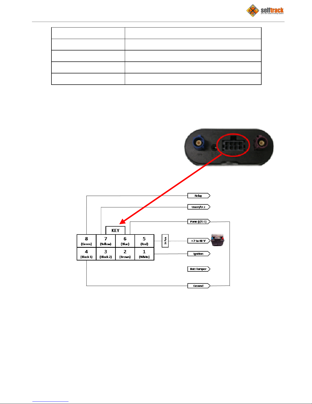
6.8 Standard Selftrack Nitro Installation configuration
The eight (8) pin external I/0 and power harness connector for the Selftrack Nitro is
included in the package. Table 1 below describes the pin functionality.
Pin Number unctionality
Pin-1 Switched Power (ignition)
Pin-2 Serial Data In (RS232)
Pin-3 Serial Data Out (RS232)
Selftrack Nitro Vehicle Tracker
User & Installation Manual
Page 14
Pin-4 Ground
Pin-5 Unswitched Power (Battery)
Pin-6 User Controlled I/0
Pin-7 User Controlled I/0
Pin-8 User Controlled Output
Table 3 - 8 Pin I/0 Connector
The Nitro allows the user the following functions:
•Battery Tamper Alert (built-in)
•Ignition ON / OFF (PIN 5)
•Panic Button (PIN 6, User I/O 1)
•User Input/Output (PIN 7, User I/O 2)
•User acti ated Relay (PIN 8)
The standard Nitro wiring is as follows:
igure 10 – Standard Nitro wiring diagram
Table of contents


