SEMAK VB250 Installation and operation manual

SEMAK VITABLEND STICK BLENDER
MODELS VB250, VB360, VB410 &VB510
SEMAK AUSTRALIA:FACTORY 18, 87-91 HALLAM SOUTH ROAD,HALLAM VIC 3803
PH 03 9796 4583 FAX 03 9796 4586 WEB WWW.SEMAK.COM.AU
OPERATION AND WARRANTY BOOKLET
VB250 VB360 VB410 VB510

Page | 2
Table of Contents
IMPORTANT...........................................................................................................................4
USES.......................................................................................................................................4
SAFETY GUIDELINES ...............................................................................................................4
FEATURES AND DIMENSIONS.................................................................................................4
INSTALLATION........................................................................................................................5
ELECTRICAL CONNECTION...................................................................................................5
MOTOR UNIT FEATURES .....................................................................................................5
PARTS CATALOGUE ................................................................................................................6
VB250 2008+.......................................................................................................................7
VB250 PARTS MODIFICATION ................................................................................................8
VB360 / VB410 / VB510 MOTOR HEAD ..................................................................................9
VB360 / VB410 / VB510 TRANSMISSION SHAFT...................................................................10
OPERATION..........................................................................................................................11
STARTING UP ....................................................................................................................11
STOP .................................................................................................................................11
CLEANING ............................................................................................................................12
CLEANING BEFORE THE FIRST USE ....................................................................................12
CLEANING AFTER USE .......................................................................................................12
MAINTENANCE ....................................................................................................................12
FAULT FINDING....................................................................................................................13
THE MACHINE DOES NOT START UP .................................................................................13
THE MACHINE STOPS........................................................................................................13
ABNORMAL NOISE-VIBRATIONS .......................................................................................13
SAFETY REGULATIONS AND STANDARDS .............................................................................13
ELECTRICAL WIRING DIAGRAM ............................................................................................14
SERVICE & MAINTENANCE ...................................................................................................14
SPARE PARTS........................................................................................................................14
WARRANTY ..........................................................................................................................14
WARRANTY REGISTRATION..................................................................................................15

Page | 3
RETAIN THESE SAFETY INSTRUCTIONS

Page | 4
IMPORTANT
To get the best performance and assure a long life of the machine, please, read carefully the
instructions given in this manual before the starting up of the machine. This manual describes the
installation, operation and maintenance of the machine.
USES
This Hand Blender allows you to prepare vegetable, fish and seafood soups, purees, different
sauces, mayonnaise, compotes, fruit and vegetable creams, etc.
SAFETY GUIDELINES
1. Keep the machine out of reach of children and infirm persons. Do not allow children to play with
the machine.
2. Never try to overcome the blocking and safety mechanisms of the machine.
3. Stop and unplug the machine before any cleaning, checking or maintenance operation.
4. Do not pull the power cord to disconnect the machine.
5. Avoid contacting moving parts. Keep hands and any utensil away from the container during
operation to reduce the risk of injury to persons and/or damage to the machine.
6. Handle the blade in a safe way, holding it with a safety glove or a thick cloth.
7. Do not operate the machine when empty or not in a container, but always inserted in the food to
be mixed.
8. Do not place the motor unit on hot surfaces or immersed in water or any other liquids.
FEATURES AND DIMENSIONS
Model
VB250
VB360
VB410
VB510
Voltage (V)
240
240
240
240
Frequency (Hz)
50
50
50
50
Power absorption (W)
at 9000 rpm
220
550
550
550
Dimension A (mm)
250
350
400
500
Dimension B (mm)
513
714
779
879
Dimension C (mm)
84
130
130
130
Dimension D (mm)
115
115
115
115
Net Weight (kg)
1.40
3.4
3.5
3.6

Page | 5
INSTALLATION
Installation must be carried out in strict compliance with the provisions of law currently in force in
Australia or country of use, with particular reference to said country's accident and fire-prevention
requirements and electricity authority regulations.
Unpack the machine completely and check that all the parts are in perfect condition. Before using it
for the first time, verify the following points:
ELECTRICAL CONNECTION
Electrical outlet required is a 10 A single phase and standardised plug.
Protect the installation with a differential circuit breaker and a 10 A fuse.
Check that the voltage of the main supply corresponds to that indicated on the rating plate of
the machine.
MOTOR UNIT FEATURES
The motor unit belongs to the Class II (Double Isolation).
The motor is universal type, AC supply, single phase, provided with a thermal protector and does
not need to be earthed.
This machine is provided with a 2 meters long PVC isolation cord and a 10 A plug.

Page | 6
PARTS CATALOGUE
VB250 2007
Item
Qty.
Description
Code
Item
Qty.
Description
Code
1
1
Kit motor
91070
10
1
Kit caps-screws D VB250
91079
2
1
Kit Power Cord
91071
11
1
Kit transmission shaft 250
91080
3
1
Kit bracket power cord
91072
12
1
Kit lower bearing bush 6x16x7
91081
4
1
Kit capacitor
91073
13
1
Kit joints
91082
5
1
Kit switch button
91074
14
1
Kit blade guard Ø 40 mm
91083
6
1
Kit upper housings
91075
15
1
Kit blade Ø 40 mm
91084
7
1
Kit screws motor 6030 DIN 7985
71076
16
1
Kit screw for blade Ø 40 mm
91085
8
1
Kit caps-screws ABC VB250
91077
17
1
Nylon Drive Coupling
91086
9
1
Kit tube 250
91078
18
1
Wall Mount
91107
Kits 1, 2, 3, 4, 5 and 6 include kits 7, 8 and 10.
Kit 9 includes kit 10.

Page | 7
VB250 2008+
Item
Qty.
Description
Code
Item
Qty.
Description
Code
1
1
Kit motor
91114
10
1
Kit caps-screws D VB250
91079
2
1
Kit Power Cord
91115
11
1
Kit transmission shaft 250
91117
3
1
Kit bracket power cord
91072
12
1
Kit lower bearing bush 6x16x7
91104
4
1
Kit capacitor
91073
13
1
Kit joints
91082
5
1
Kit switch button
91074
14
1
Kit blade guard Ø 40 mm
91083
6
1
Kit upper housings
91075
15
1
Kit blade Ø 40 mm
91084
7
1
Kit screws motor 6030 DIN 7985
71076
16
1
Kit screw for blade Ø 40 mm
91085
8
1
Kit caps-screws ABC VB250
91077
17
1
Nylon Drive Coupling
91118
9
1
Kit tube 250
91116
18
1
Wall Mount
91107
Kits 1, 2, 3, 4, 5 and 6 include kits 7, 8 and 10.
Kit 9 includes kit 10.

Page | 8
VB250 PARTS MODIFICATION
The VB250 experienced a parts modification in 2008. The model you have can be determined by the
drive shaft with the current model having a flat spline of approximately 20mm. This range of
electroportables has been exclusively designed to make the assembling and disassembling of all the
parts easier, especially of those that have to be handled frequently because of cleaning and
maintenance purposes.
For the assembling/disassembling of the parts, first place the machine in the vertical position, with
the blade looking up. The blade is inserted into the lowest extremity of the transmission shaft with
the help of a screw. For assembling/disassembling, the operator only needs a screwdriver. To
handle the blade in a safe way, hold it always with a safety glove/thick cloth (Step 1, Figure 1).
The blade guard is attached to the tube by a thread. To detach it, turn it in the direction of the
arrow (Step 2, Figure 1). Once the blade out of the guard, the transmission shaft, the bearing bush
and the joints will be free to be taken out (Step 3, Figure 1).
To reassemble the set, insert the transmission shaft with the bearing bush and the inner joint in the
tube till it clicks. Press the bearing bush. If it does not enter totally (keeps about 10 mm out), turn
and push the shaft following the Step 4, Figure 1 till the bearing bush is totally in. To finish, thread
the guard with the outer joint in the tube and follow Step 1 in the opposite way of the
disassembling.
Step 1 Step 2 Step 3 Step 4
Figure 1
REMARK: To thread the screw, align the cavity of the shaft with that of the blade and place the blade
on the shaft extremity level (Figure 2).
Incorrect Incorrect Correct
Figure 2
blade guard
outer joint
inner joint
bearing bush
transmission
shaft

Page | 9
VB360 / VB410 / VB510 MOTOR HEAD
DIAGRAM
PART
SEMAK PART
NO
DESCRIPTION
1
91500
KIT MOTOR VB360 / VB410
91501
KIT MOTOR VB510
2
91502
KIT MOTOR LOWER SUPPORT
3
91503
KIT SCREWS
4
91504
KIT LOWER HOUSING
5
91505
KIT BRACE 450W
KIT BRACE 550W
6
91506
KIT UPPER HOUSING
7
91507
KIT SCREWS UPPER HOUSING
8
91508
KIT SAFETY STOP BUTTON
9
91509
KIT POWER CORD
10
91510
KIT BRACKET POWER CORD
11
91511
KIT SPEED CONTROL
12
91512
KIT COMMAND BUTTON
13
91513
KIT CAP SCREWS
14
91514
KIT COUPLING

Page | 10
VB360 / VB410 / VB510 TRANSMISSION SHAFT
PART
CODE
DESCRIPTION
1
91515
KIT TUBE TF360
91516
KIT TUBE TF410
91517
KIT TUBE TF510
2
91518
KIT TRANSMISSION SHAFT 360
91519
KIT TRANSMISSION SHAFT 410
91520
KIT TRANSMISSION SHAFT 510
PART
CODE
DESCRIPTION
3
91521
KIT INOX BALL BEARING 6082RS
4
91522
KIT COUPLING TF 410
5
91523
KIT OIL SEAL 8X22X7
6
91524
KIT JOINTS BT
7
91525
KIT BLADE GUARD Ø 60MM
8
91526
KIT BLADE Ø 60MM
9
91527
KIT LOWER BEARING BUSH BT

Page | 11
OPERATION
STARTING UP
Insert the plug in the socket outlet for the
connection of the machine.
Hold the machine by its handle and only
immerse the attachment in the container to
2/3 of its length at most. The special shape of
the handle makes the machine take the
correct inclination without forcing the
operator to turn the wrist or to make an extra
effort to work.
With the safety button pressed (Step 1, Figure
3), press the trigger (Step 2, Figure 3). The
machine will start up.
Maintain the trigger pressed on and release
the safety button to continue the operation.
Figure 3
STOP
Release the trigger.
Unplug the machine.
WARNING!
Never operate the machine when empty or not in a container, but always inserted in the food to be
mixed.
When preparing fruit-based mixtures, cut the fruit beforehand and remove seeds/stones.
Do not use the machine with hard ingredients (coffee, ice-cubes, chocolate, etc).
safety button
Step 1
Step 2
trigger

Page | 12
CLEANING
Before any cleaning, stop and unplug the machine.
CLEANING BEFORE THE FIRST USE
Clean the tube, the blade guard and the blade in hot water and a detergent compatible with
this type of material.
Rinse and dry them carefully.
CLEANING AFTER USE
Operate the machine in a hot and clean water container for some seconds in order to remove
residues from the blade, the blade guard and the tube.
Dismount the machine as suggested in Figure 1. If the machine has been used in a hot
preparation, leave it cool off before disassembling it.
The tube, the blade guard and the blade must be washed in a plenty of clean water and a
detergent compatible with this type of material. Before drying, rinse with clean water.
To clean the transmission shaft and the lower bearing bush use a brush.
Disinfect all the parts in constant contact with the food with the help of a smooth cloth
impregnated with ethyl alcohol 90º.
To clean the motor unit, use a damp cloth or a sponge and dry it next.
WARNING!
Do not immerse the motor unit under running water or immerse it in water or any other liquids to
avoid electrical shocks.
MAINTENANCE
Before any maintenance, stop the machine and unplug it.
The result of the mixture will depend basically in the condition of the blade. It gets damaged
with the use and it will have to be replaced periodically to obtain the best quality of the
mixture.
Check the joints and the oil seal regularly and replace them if necessary, in order to maintain
the machine in a perfect condition.
Check periodically that the air grills are not closed up.
Never use the machine if the power cord is damaged. An Authorised After Sales Agent should
only replace it.

Page | 13
FAULT FINDING
THE MACHINE DOES NOT START UP
Check the following points:
The machine is not properly plugged. Check if the plug is wrongly connected to the outlet.
There has been a cut of the power supply.
THE MACHINE STOPS
Check the following points:
There has been a cut. Stop and unplug the machine. Wait till the power comes back and restart the
machine up.
The motor is overloaded. Stop and unplug the machine and wait some minutes so that the motor
can cool off. After a cooling off period it can be turned on again.
ABNORMAL NOISE-VIBRATIONS
Check the following points:
Water has entered into the attachment. Dismount the parts following Point 5.2 and dry them next.
Sealing parts to avoid leaks (the joints and/or the oil seal) are damaged. If so, replace them.
The transmission parts (the shaft and the bushing) are damaged. If so, replace them.
WARNING!
If the problems persist, contact an Authorised After Sales Agent.
SAFETY REGULATIONS AND STANDARDS
This product has been manufactured in compliance with the Directives and the Standards in force in
the E.U. Protection Indices IP34.
The level of noise of the machine operating, placed 1,6 meter high and measured at a distance of 1
meter is:
76 dB (A), precision ±2 dB(A).
Background noise: 40 dB(A).
Semak Vitablend complies with the following electrical standards
Compliance CISPR 14

Page | 14
ELECTRICAL WIRING DIAGRAM
SERVICE & MAINTENANCE
For Service and Repair, contact Semak for your nearest Authorised Service Agent
The Foodservice Industry is deemed a hostile environment within the scope of AS/NZS 3760:2003.
Semak Vitablend MUST be routinely electrically tested for compliance with this standard if used
commercially.
It is recommended that a Food Safety program such as HACCP be employed and that routine service
and repair be undertaken at the time of electrical testing to ensure the correct operation and
function of all parts. The equipment MUST be serviced annually or sooner depending of the hostility
of the environment in which it is operated.
SPARE PARTS
Spare Parts, exploded views and wiring diagrams are available from our webpage. Go to
www.semak.com.au and locate the appliance in the product section for the above information.
WARRANTY
Vitablend Stick Blenders are Commercial Grade blenders suitable for light commercial and domestic
use. This product is guaranteed for 12 months from the date of purchase against mechanical and
electrical defects. If the fault is deemed caused by MISUSE/ABUSE the terms of the warranty are
invalidated. If the product has been opened or tampered with (ie. In an attempt to repair it) the
warranty is invalidated. All warranty repairs should be undertaken by Dimark Commercial Pty. Ltd.
It is against company policy to authorize warranty repairs over the phone. Service Agents will
require a work order number from Semak to conduct warranty repairs.
F
N
ON/OFF SWITCH
CM

Page | 15
WARRANTY REGISTRATION
Retain for Future Reference
DO NOT SEND
Please complete one registration for each Semak appliance.
You may be required to provide this information when requesting after sales service. Please
staple your proof of purchase to this page.
Company Name: ________________________________________________
Company Address: ________________________________________________
Business Type: ________________________________________________
Contact: ________________________________________________
Phone: ________________________________________________
Fax: ________________________________________________
Email: ________________________________________________
Product: ________________________________________________
Serial Number: ________________________________________________
Date of Purchase: ________________________________________________
Place of Purchase: ________________________________________________

Page | 16
© Semak 2014
This manual suits for next models
3
Table of contents
Other SEMAK Blender manuals

SEMAK
SEMAK VB200 Installation and operation manual
SEMAK
SEMAK VCE1500 Installation and operation manual
SEMAK
SEMAK VB180 Installation and operation manual
SEMAK
SEMAK BBDD Installation and operation manual
SEMAK
SEMAK VCM1050S Installation and operation manual

SEMAK
SEMAK VCE1500B Installation and operation manual
Popular Blender manuals by other brands

Thane Housewares
Thane Housewares Thunder Stick Pro instructions

Oster
Oster BLSTMG-W00 instruction manual

Scarlett
Scarlett SC-HB42F33 instruction manual
eta
eta MINESTRO Instructions for use
Tailgator
Tailgator The Original Portable Gas Powered Blender instruction manual
Cuisinart
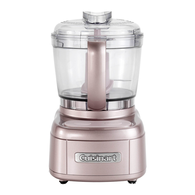
Cuisinart Mini Prep Pro ECH4 Series user manual
