sematic SDS User manual

Drive - Instruction Manual
8XX
E 2016-03-25
SDS Drive DC-PWM
Compatible
811-000-000
ENGLISH


3
811-000-000 SDS© DC-PWM Compatible • Edition 25 March 201
ENGLISH
www.sematic.com
Changes can be made without notice
1 Preface . . . . . . . . . . . . . . . . . . . . . . . . . . . . . . . . . . . . . . . . . . . . . . . . . . . . . . . . . . . . . . . . . . . . . . . . . . . . . . . . . . . . . . . . . . . . . . . . . . . . . . . . . . . . 7
2 What is the Sematic DC-PWM Drive System© Compatible? . . . . . . . . . . . . . . . . . . . . . . . . . . . . . . . . . . . . . . . . . . . . . . . . . . . . . . . . . . . . . . . . . 9
2.1 Speed profile 10
General Features . . . . . . . . . . . . . . . . . . . . . . . . . . . . . . . . . . . . . . . . . . . . . . . . . . . . . . . . . . . . . . . . . . . . . . . . . . . . . . . . . . . . . . . . . . . . . . . . . . . 11
3.1 Technical information 11
3.2 Sematic Drive System© Door Controller (DC-P M) 11
4 Signals to/from the door controller . . . . . . . . . . . . . . . . . . . . . . . . . . . . . . . . . . . . . . . . . . . . . . . . . . . . . . . . . . . . . . . . . . . . . . . . . . . . . . . . . . . . 12
4.1 Sematic Drive System© (DC-P M) COMPATIBLE connections 12
4.2 Sematic Drive System© set-up and incoming/outgoing signals from the door controller 13
4.3 Detector/Photocell/Barriers: Signal-Only Connection to the Door Controller (Direct Connection) 15
4.4 Detector/Photocell/Barriers: Complete Connection to the Door Controller 15
4.5 Magnetic Switches 17
5 Instruction without handset . . . . . . . . . . . . . . . . . . . . . . . . . . . . . . . . . . . . . . . . . . . . . . . . . . . . . . . . . . . . . . . . . . . . . . . . . . . . . . . . . . . . . . . . . . 18
5.1 Automatic Mode “AUTO” 18
5.2 Manual Mode “MAN” 18
5.3 Programming Mode “PROG” 19
6 Functions available . . . . . . . . . . . . . . . . . . . . . . . . . . . . . . . . . . . . . . . . . . . . . . . . . . . . . . . . . . . . . . . . . . . . . . . . . . . . . . . . . . . . . . . . . . . . . . . . . 21
6.1 Reversing system force setting 21
6.2 Reversing System choice: INTERNAL or EXTERNAL 21
6.3 Limited Door Reversal 21
6.4 Main Lift Controller Test 21
6.4.1 No MLC Signal 21
6.4.2 Main Lift Controller Input Alarm 21
6.5 Car Door Locking Device (USA = Restrictor) 21
6.6 Full or framed Glazed Paneled Doors 21
6.7 Aux Output Relay 22
6.7.1 Space Percentage 22
6.7.2 Gong hile Opening 22
6.8 Forced Closing (Nudging) 22
6.9 Protective Device Logic Kn 22
6.10 Emulation Type 22
6.11 Alarms 23
7 Instruction with handset . . . . . . . . . . . . . . . . . . . . . . . . . . . . . . . . . . . . . . . . . . . . . . . . . . . . . . . . . . . . . . . . . . . . . . . . . . . . . . . . . . . . . . . . . . . . . 24
7.1 Handset (optional) 24
7.2 User Handset menus and submenus 25
7.3 Reversing System Force setting by means of the handset 26
7.4 Speed Profile and High Speed adjustments by means of the Handset 26
7.4.1 Option “Fast settings” 26
7.5 Option “Advanced Settings” 27
7.5.1 Option “Opening Parameters” 27
7.5.2 Option “Closing Parameters” 28
7.5.3 Option “Change Password” 28
7.5.4 Option “Reset speed” 28
7.5.5 Option “Input levels logic” 28
7.5.6 Option “Opening slow down delay to opening rest current” (Only for digidoor emulation) 29
7.5.7 Option “Closing limit delay to closing rest current” (Only for digidoor emulation) 29
7.6 Option “Reserved Area” 29
8 General option . . . . . . . . . . . . . . . . . . . . . . . . . . . . . . . . . . . . . . . . . . . . . . . . . . . . . . . . . . . . . . . . . . . . . . . . . . . . . . . . . . . . . . . . . . . . . . . . . . . . . 0
8.1 Reversing System Setting by means of the Handset 30
8.2 Activation of the Main Lift Controller Test by means of the Handset 30
8.3 Activation of the Main Lift Failure by means of the Handset 30
8.4 Main Lift Controller Alarm - (MLC Input Alarm) 31
8.5 Limited door reversal Activation by means of the handset 31
8.6 Activation of the Car Door Locking Device setting by means of the Handset 31
8.7 Activation of the Glazed Paneled doors setting by means of the Handset 31
8.8 AUX Output Relay setting by means of the Handset 32
8.9 Protective Device Logic Kn setting by means of the Handset 32
8.10 Emulation Type 32

4
811-000-000 SDS© DC-PWM Compatible • Edition 25 March 201
ENGLISH
www.sematic.com
Changes can be made without notice
9 Maintenance Menu - diagnostics and alarm management . . . . . . . . . . . . . . . . . . . . . . . . . . . . . . . . . . . . . . . . . . . . . . . . . . . . . . . . . . . . . . . . .
9.1 Consulting the Maintenance Menu with the Handset 33
10 Controller software upgrade . . . . . . . . . . . . . . . . . . . . . . . . . . . . . . . . . . . . . . . . . . . . . . . . . . . . . . . . . . . . . . . . . . . . . . . . . . . . . . . . . . . . . . . . . . 5
11 Upgrade from controllers previous to F28/F29 controller (Controller type: ASC 10/20, ADC10/11, SEM10/11, LMDC 10/11) F28/29 B . . . . 6
12 Upgrade from F28/F29 and LMDC 2010/2011/DIGIDOOR . . . . . . . . . . . . . . . . . . . . . . . . . . . . . . . . . . . . . . . . . . . . . . . . . . . . . . . . . . . . . . . . . . . 8
1 Upgrade from F28/F29 controller . . . . . . . . . . . . . . . . . . . . . . . . . . . . . . . . . . . . . . . . . . . . . . . . . . . . . . . . . . . . . . . . . . . . . . . . . . . . . . . . . . . . . . 9
14 Upgrade from F28/F29 controller rel. 2.0 Controller . . . . . . . . . . . . . . . . . . . . . . . . . . . . . . . . . . . . . . . . . . . . . . . . . . . . . . . . . . . . . . . . . . . . . . . 41
15 Upgrade from LMDC 2010/11 controller . . . . . . . . . . . . . . . . . . . . . . . . . . . . . . . . . . . . . . . . . . . . . . . . . . . . . . . . . . . . . . . . . . . . . . . . . . . . . . . . 42
16 Upgrade from Digidoor Controller . . . . . . . . . . . . . . . . . . . . . . . . . . . . . . . . . . . . . . . . . . . . . . . . . . . . . . . . . . . . . . . . . . . . . . . . . . . . . . . . . . . . . 4
17 Door operator maintenance . . . . . . . . . . . . . . . . . . . . . . . . . . . . . . . . . . . . . . . . . . . . . . . . . . . . . . . . . . . . . . . . . . . . . . . . . . . . . . . . . . . . . . . . . . 44
18 Spare parts . . . . . . . . . . . . . . . . . . . . . . . . . . . . . . . . . . . . . . . . . . . . . . . . . . . . . . . . . . . . . . . . . . . . . . . . . . . . . . . . . . . . . . . . . . . . . . . . . . . . . . . . 44

ENGLISH
www.sematic.com
Changes can be made without notice
5
811-000-000 SDS© DC-PWM Compatible • Edition 25 March 201
Confidentiality agreement Disclaimer
The software/hardware “Sematic Drive System©” and all the relevant information, ideas, concepts and know-how
are confidential and the exclusive property of Sematic.
All information relevant to this instruction manual and any other support supplied by Sematic must be kept
confidential and proprietary to Sematic and shall not to be copied or reproduced in any form whatsoever.
Any information contained in the “Sematic Drive System©” shall not be disclosed to anyone, without Sematic's
written consent apart from authorized representatives employed by the user which commits itself to the
confidentiality clause.
The Company that makes use of the Sematic Drive System©, binds itself not to use confidential informations
owned by Sematic and not to compile or reingineer the Sematic Drive System© and any information in it
contained.
© Sematic Spa. All rights reserved.
Sematic regards all the information contained in this instruction manual to be correct at the time of printing. This information does not constitute any obligation to Sematic
and can be modified without prior notification. Sematic cannot be held responsible for any possible damages or claims caused to items or persons due to errors or
misunderstandings within the contents of this instruction manual.
Please dispose of the
controller correctly.
Bitte entsorgen Sie das
Türsteuergerät auf korrekte Weise.
Si prega di differenziare
correttamente il controller.
Prière de distinguer
correctement le controller.
Rogamos diferenciar la controla
corectamente.
cod. 1020211-263

ENGLISH
www.sematic.com
Changes can be made without notice
811-000-000 SDS© DC-PWM Compatible • Edition 25 March 201
-
Sematic Group:
we care about your integrated solution!
OMPONENT SYSTEMS
• Automatic lift doors
• Frame and frameless glass doors
• Enhanced car door operator solutions
• Complete cabins
• Car Frames
• Custom integrated packages
• Special lift doors, cabins and car frames
ELEVATOR SYSTEMS & SUBSYSTEMS
• Rope traction elevators
• Machineroomless roped elevators
• Modular hydraulic elevators
• Hydraulic elevators
• Panoramic elevators
• Hospital elevators
• Special executions

ENGLISH
www.sematic.com
Changes can be made without notice
Preface
7
811-000-000 SDS© DC-PWM Compatible • Edition 25 March 201
1 PREFA E
This manual has been drafted taking into account that the Company installing genuine Sematic products will
comply with the following necessary requirements:
• personnel responsible for the installation and/or maintenance of the doors must be familiar with the General
and Specific regulations in force on the subjects of work safety and hygiene (89/391/CEE - 89/ 54/CEE - 89/
5 /CEE);
• personnel responsible for the installation and/or maintenance must be familiar with the Sematic product and
must have been trained by Sematic or by an authorized Sematic agent;
• installation equipment used must be in good working order with all measuring instruments calibrated (89/ 55/
CEE).
Sematic:
• undertakes to update the present manual and send the customer copies of all new updates together with
material;
• within its continuous product improvement policy, reserves the right to make changes to the designs and
materials of its products. Sematic will give an agreed reasonable time to all its customers to allow them to
adapt to the new changes their complementary current constructions;
• guarantees a good performance only of the original parts sold directly and correctly installed.
Therefore:
parts manufactured and/or added to the Sematic product without having it checked by Sematic, or non-original
parts based upon a Sematic design (even if supplied by authorised agents) cannot be considered under guarantee
since the following conditions have not been ensured:
1. Quality control of raw material supply
2. Process control
3. Product control
4. Conformity tests according to Sematic specifications
Furthermore, Sematic
• guarantees the performance life of its products only if correctly stored (indoors storage at temperatures
ranging between -10 and + 0 °C out of direct sunlight) and correctly installed;
• guarantees the perfect performance of the products installed in environments with temperatures between -10
and + 0 °C and with a non-condensing, relative humidity level inbetween 20% and 80%. (Special note: for
temperatures and humidity rates outside these ranges, please consult our Technical Dept.)
The present document has been drafted in accordance with the following EU Directives:
• 98/37/CE Machinery Directive and subsequent modifications (when applicable)
• 95/1 /CEE Lifts Directive
• 2014/33/EU Lifts Directive
• 93/ 8/CEE Markings
• 90/2 9/CEE Heavy loads handling
• Noise (Acoustic emission) 8 /188/CEE modified according to Directive 98/24/CEE
• Electromagnetic compatibility 89/33 /CEE
and with the following particular standards:
• EN81-1/2;
• EN81-20/50;
• AS17535;
• EN12015/EN1201 ;
• EN13015
Taking into account, during all project planning, the Risk Assessments relating to:
a. RISKS OF ME HANI AL HAZARDS
• Squeezing during operations
• Squeezing after Trapping caused by friction (glass panels)
• Cuts caused by sharp edges, or static sharp pieces

8
ENGLISH
www.sematic.com
Changes can be made without notice
Preface
811-000-000 SDS© DC-PWM Compatible • Edition 25 March 201
b. RISKS OF ELE TRI AL HAZARDS
• Persons in contact with energized parts (direct contact)
• Persons in contact with parts that become energized due to a fault (indirect contact)
c. RISKS OF OVERHEATING
d. RISKS GENERATED BY NOISE
e. RISKS GENERATED BY VIBRATION
f. RISKS GENERATED BY MATERIALS AND SUBSTAN ES

ENGLISH
www.sematic.com
Changes can be made without notice
What is the Sematic DC-PWM Drive System© Compatible?
9
811-000-000 SDS© DC-PWM Compatible • Edition 25 March 201
2 WHAT IS THE SEMATI D -PWM DRIVE SYSTEM© OMPATIBLE?
The System consists of:
• a Car Door Operator (1)
• a microprocessor-based Door Controller (2)
• DC Motor (3)
• Megnetic Switches with activation magnets (4)
The Sematic Drive System© automatically controls the opening and closing of the lift doors, monitoring the
timing, current variations, speeds (high, low, acceleration and deceleration curves), various safety systems
(reversing system, Limited Door Reversal etc.) and faults (high voltage, signal failure, ...).
There are two independent speed curve profiles for the opening and closing cycles (5) which can be modified by
means of the door controller push buttons or by means of the Sematic handset (an optional 8 digit keypad and
display accessory which can be connected to the card by an RJ45 plug).
The handset ( ) is a key pad that allows viewing and modification of the function parameters stored in the
controller.
It is important to use the Sematic handset for installation or maintenance, as it enables viewing and/or variation
of the controller parameters, systems, and operation errors.
Furthermore, it is possible to use the Sematic handset directly from the inside of the car (7).
Making it possible to monitor and modify the door operating parameters from a completely safe position, and also
to control the movement of the coupled car and landing doors during their effective operating cycle.
Note: the pictures on this document are examples only; real components appearances may differ according to
supplied configuration of door operator and motor.
10
ENGLISH
www.sematic.com
Changes can be made without notice
What is the Sematic DC-PWM Drive System© Compatible?
811-000-000 SDS© DC-PWM Compatible • Edition 25 March 201
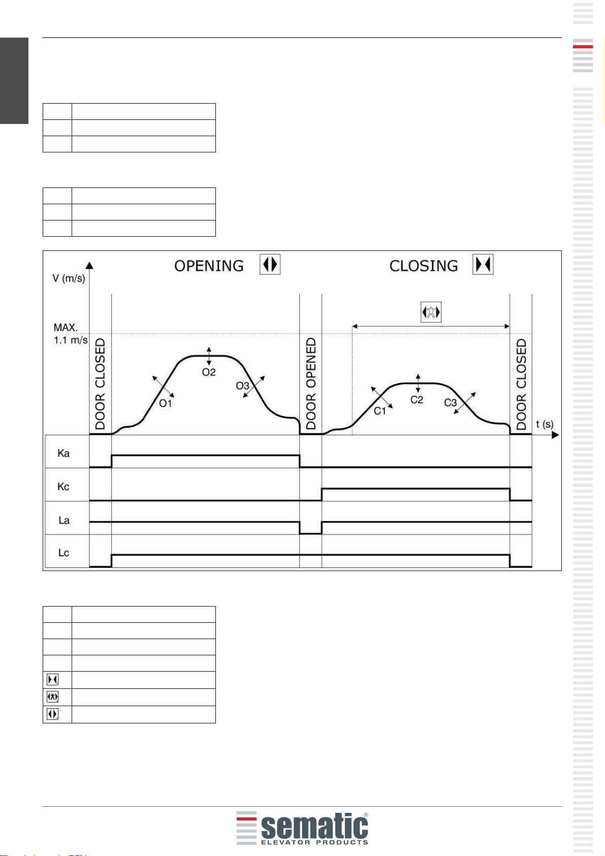
2.1 SPEED PROFILE
Opening cycle
losing cycle
Key
O1 Opening acceleration
O2 Opening hight speed
O3 Opening deceleration
C1 Closing acceleration
C2 Closing hight speed
C3 Closing deceleration
Ka Door opening
Kc Door closing
La Open Limit
Lc Close limit
Closing cycle
Active reversing system
Opening cycle

ENGLISH
www.sematic.com
Changes can be made without notice
General Features
11
811-000-000 SDS© DC-PWM Compatible • Edition 25 March 201
3 GENERAL FEATURES
3.1 TE HNI AL INFORMATION
3.2 SEMATI DRIVE SYSTEM© DOOR ONTROLLER (D -PWM)
1. Power ON button
2. Power OFF button
3. Display
4. Manual mode buttons
5. RJ45 Connection port (Handset)
. poles motor and auxiliary EOD battery power supply connector (cod. E0 AARX-05)
7. RJ45 Connection port (Motor optical Encoder)
8. 4 poles detector / photocells connector (cod. E0 AARX-0 )
9. poles Main Lift Controller signals connector (cod. E0 AARX-03)
10. poles Main Lift Controller signals connector (cod. E0 AARX-04)
11. 10 poles Main Lift Controller signals connector (cod. E0 AARX-07)
MAIN SUPPLY VOLTAGE 90-290 Vac (115 V-20%, 230V+2 %), 50- 0 Hz
TYPICAL POWER CONSUMPTION 200 VA
PEAK POWER CONSUMPTION 300 VA
MOTOR OVERLOAD PROTECTION @In <15 minutes
@2In <3 minutes
OPERATIONAL TEMPERATURE
RANGE
from -10°C to + 0°C
HUMIDITY non-condensing between 20% and 80%
PROTECTION rapid cartridge fuse [5x20, 4 A]
battery fuse [5x20, 8 A]
PERFORMANCE SPEED separately adjustable for opening and closing
REVERSAL SENSITIVITY Variable, only operational on door closing cycle
12
ENGLISH
www.sematic.com
Changes can be made without notice
Signals to/from the door controller
811-000-000 SDS© DC-PWM Compatible • Edition 25 March 201
4 SIGNALS TO/FROM THE DOOR ONTROLLER
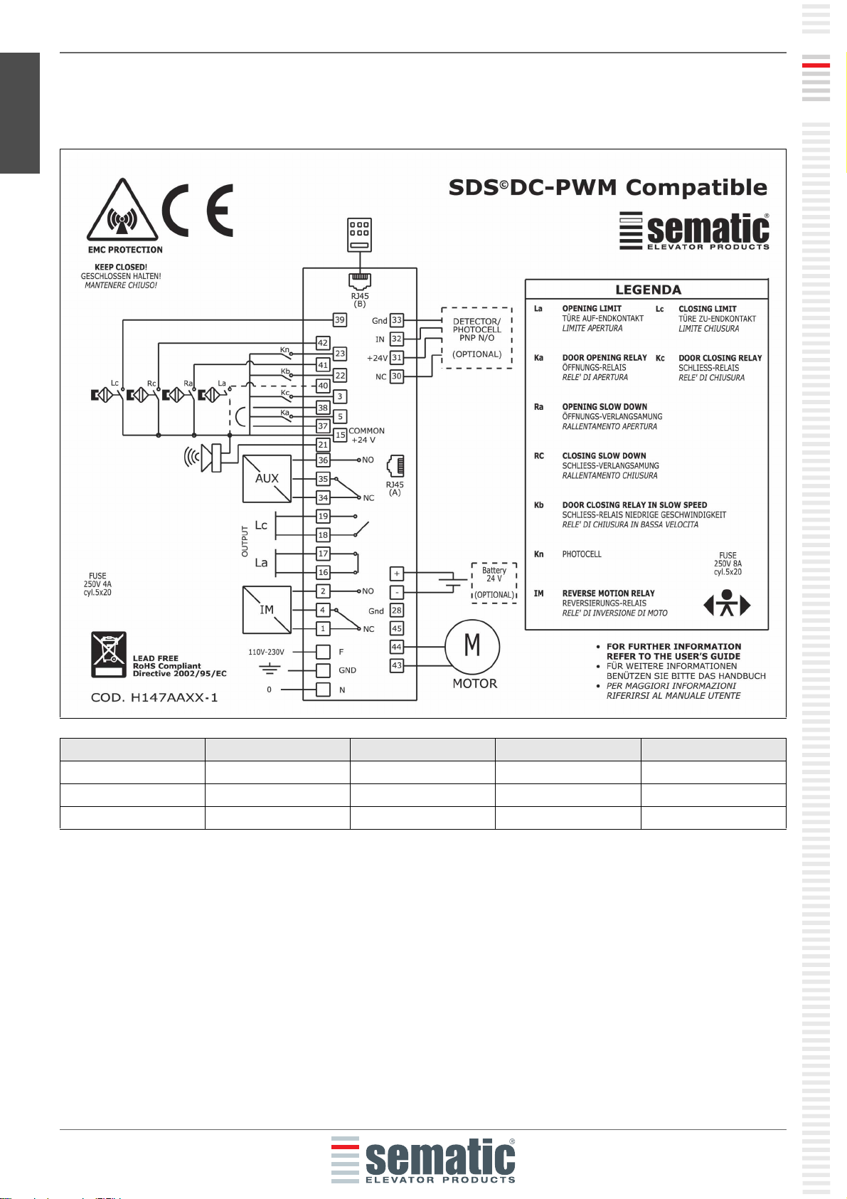
4.1 SEMATI DRIVE SYSTEM© (D -PWM) OMPATIBLE ONNE TIONS
DOOR POSITION L SWIT H STATE R SWIT H STATE RA SWIT H STATE LA SWIT H STATE
Door closed OPEN CLOSED OPEN CLOSED
Door mid travel CLOSED OPEN OPEN CLOSED
Door open CLOSED OPEN CLOSED OPEN

ENGLISH
www.sematic.com
Changes can be made without notice
Signals to/from the door controller
13
811-000-000 SDS© DC-PWM Compatible • Edition 25 March 201
4.2 SEMATI DRIVE SYSTEM© SET-UP AND IN OMING/OUTGOING SIGNALS FROM THE DOOR
ONTROLLER
1 Magnetic switches
2 Safety chains
3 Main Lift Controller
4 Photocells or Detector

14
ENGLISH
www.sematic.com
Changes can be made without notice
Signals to/from the door controller
811-000-000 SDS© DC-PWM Compatible • Edition 25 March 201
-
Note: Sematic Drive System© controller may be used also with incoming signal from the Main Lift Controller with
voltage range between and 24 Vdc.
To use this feature:
• Remove the shunt between 37-38 connector pins
• Connect the 38 connector pin at the 0V DC external incoming signal Power supply
IN OMING SIGNALS FROM THE DOOR ONTROLLER
Signal Connector Pins Contact type & normal state Note
Opening control Ka
(coming from the Main Lift
Controller)
Connector pins
5-15
These connections require dry
(voltage free) contacts (contact
open when inactive)
When the Door Controller is
installed on a Front & Rear
entrance car, it is important that
the opening and closing
commands have no common
contacts between the two doors.
Shielded, Grounded Wire Highly
Recommended
Closing control Kc
(coming from the Main Lift
Controller)
Connector pins
3-15
These connections require dry
(voltage free) contacts (contact
open when inactive)
Forced closing control at low
speed Kb
Connector pins
15-22
These connections require dry
(voltage free) contacts (contact
open when inactive)
The main lift controller may signal
the forced closing when the
photocell (or similar device) shall
be made inoperative due to a
failure, or after several door
closing failures.
Re-opening control Kn Connector pins
15-23
These connections require dry
(voltage free) contacts (both
logics available)
See 4.1 & 4.2 for the connection
to the door controller
Closing limit switch contact Lc Connector pins
15-39
These connections require dry
(voltage free) contacts (contact
open when door is closed)
From the operator closing limit
magnetic switch
Closing slow down contact La Connector pins
15-42
These connections require dry
(voltage free) contacts (contact
open when door is open)
From the operator closing limit
magnetic switch
Opening limit switch contact Rc Connector pins
15-40
These connections require dry
(voltage free) contacts (contact
open when inactive)
From the operator opening limit
magnetic switch (Nnot used for
DIGIDOOR compatibility).
Opening slow down contact Ra Connector pins
15-41
These connections require dry
(voltage free) contacts (contact
open when inactive)
From the operator opening slow
down magnetic switch
Handset (Optional) Connector RJ45 (B)

ENGLISH
www.sematic.com
Changes can be made without notice
Signals to/from the door controller
15
811-000-000 SDS© DC-PWM Compatible • Edition 25 March 201
-
• For the Door Operator mechanical installation refer to the “Installation and maintenance of Sematic doors”
manual.
• Warning: to avoid possible induced currents within field wiring, it is recommended to shield the Ka and Kc
signals (connector pins 3, 5 and 15) with grounded, shielded cables.
• Changes made to the factory wiring length or position can damage the EMC system characteristics and is not
recommended.
4.3 DETE TOR/PHOTO ELL/BARRIERS: SIGNAL-ONLY ONNE TION TO THE DOOR ONTROLLER
(DIRE T ONNE TION)
This connection requires a dry (voltage free) external relay contact connected to the Door Controller Connector
pins 15 & 23.
If desired, it is possible to connect the single output signal from a photocell (or similar device) formed by a voltage
free contact, so that the door controller will directly receive the command to re-open.
The photocell (or similar device) has therefore an independent power supply and sends only its outgoing signal to
the Sematic Drive System© controller.
Reopening is operated according to the REVERSING SYSTEM, LIMITED DOOR REVERSAL EFFECT and PROTECTIVE
DEVICE LOGIC settings (see sections § .2 (pg. 21), § .3 (pg. 21) and § .9 (pg. 22)).
4.4 DETE TOR/PHOTO ELL/BARRIERS: OMPLETE ONNE TION TO THE DOOR ONTROLLER
Complete Connection means that the device draws its power supply from and sends the re-open signal directly
and only to the Sematic Drive System© controller.
It is possible to have the complete connection of detectors or photocells with a 24 Vdc max 100 mA supply and a
PNP N/O or N/C output, through the connector pins:
OUTGOING SIGNALS FROM THE DOOR ONTROLLER
Signal Connector Pins Contact type & Normal state Notes
Opening limit switch contact La Connector pins
1 -17
These connections provide dry
(voltage free) contact.
The contact is open when the door
is fully open.
Contact rating: 3A 250Vac 30Vdc
Closing limit switch contact Lc Connector pins
18-19
These connections provide dry
(voltage free) contact.
The contact is open when the door
is fully closed.
Contact rating: 3A 250Vac 30Vdc
Reversing system signal IM Connector pins
1-4
These connections provide dry
(voltage free) contact.
(contact normally closed)
This signal is generated by dry
(voltage free) Form C contacts
(relay within the Door Controller)
and is activated only when either
a mechanical obstacle (excessive
force) prevents the doors from
closing, or a signal is received
from an external safety device
that is connected to the door
controller.
It is used to signal the main lift
controller to interrupt the door
close command and give a door
open signal. Contact rating: 3A
250Vac 30Vdc
Connector pins
2-4
(contact normally open)
Auxliary autput signal AUX Connector pins
34-35
These connections provide dry
(voltage free) contact.
(contact normally open
These contacts can be used to
signal that a particular (pre-set)
door opening distance has been
achieved, or as a Gong or Buzzer
while the door is opening or as a
Thermic alarm signal.
Contact rating: 3A 250Vac 30Vdc.
Connector pins
35-3
(contact normally closed)
Motor Connector pins
43-44-45
Factory-prewired connector
Acoustic alarm (BUZZER)
Optional
Connector pins
15-21
These connections provide a
24Vdc, 100ma contact. Contact is
open when not active.

1
ENGLISH
www.sematic.com
Changes can be made without notice
Signals to/from the door controller
811-000-000 SDS© DC-PWM Compatible • Edition 25 March 201
Connector pin 30 can be used as a pass-through (dummy) connector pin for connections between the detector
system components.
The operating reopening modes depend upon the setting of the REVERSING SYSTEM, LIMITED DOOR REVERSAL
EFFECT and PROTECTIVE DEVICE LOGIC settings (see sections § .2 (pg. 21), § .3 (pg. 21) and § .9 (pg. 22))
1 Example of photocells/barriers with transmitter and receiver connected between themselves through the dummy
free connector pin 30
33 GND ground connector pin
32 IN PNP N/O or N/C signal from
detector/photocell/barrier
31 + 24 Vdc Vdc power supply to
detector/photocell/barrier
30 NC dummy free connector pin
(it can be used as a dummy connector for connection
between the detectors system components).

ENGLISH
www.sematic.com
Changes can be made without notice
Signals to/from the door controller
17
811-000-000 SDS© DC-PWM Compatible • Edition 25 March 201
4.5 MAGNETI SWIT HES
Verify that the magnet (1) has the countersink for the self-threading screw on the side of the magnetic switch (2).
Open and close the door by means of the controller or manually and make sure that the magnetic switches work
correctly.
For K1-2-3R
For K1-2-3L and K2-4-6
These are the operations of the magnetic switches:
•losed door - the door close limit (pre-adjusted by the manufacturer) must operate when the carriage has
already stopped but the retractable skate is not closed;
•Open door - the door open limit (pre-adjusted by the manufacturer) must operate approx 5 mm before the
door is totally open; (note: not used for DIGIDOOR operator compatibility);
• The closing slow down limit causes the doors to slow down before they are totally closed;
• The opening slow down limit causes the doors to slow down before they are totally open.
Attention: the distance between the slowing limits can be adjusted according to specific needs.
Fig. 1 Looking from the landing the switches are marked this way.

18
ENGLISH
www.sematic.com
Changes can be made without notice
Instruction without handset
811-000-000 SDS© DC-PWM Compatible • Edition 25 March 201
5 INSTRU TION WITHOUT HANDSET
Display in Automatic and Manual Mode
5.1 AUTOMATI MODE “AUTO”
• When the Door Controller is working in automatic mode the “AUTO” red led is on, whereas the other two red
leds are off.
• When the Door Controller is switched on, or after a self-resetting, it starts directly in the automatic mode.
• All the signals sent by the main lift controller and by the external devices (barriers, photocells, etc.) are active
in this mode.
• Keys 2 and 3 are not functional during automatic mode.
• When Key 4 is kept pressed for a while, the Door Controller (ca. 3 sec.), switches to the manual mode “MAN”.
5.2 MANUAL MODE “MAN”
• When the Door Controller is working in manual mode the “MAN” red led is on, whereas the other two red leds
are off.
• All signals coming from the main lift controller and from other external devices are ignored.
• The IM contact is deactivated, therefore the Door Controller does not recognize any signal coming from the
external devices to reverse door movement, such as photocells or barriers.
• Opening and Closing commands may be manually input by pushing Key 2 (open) or Key 3 (close).
• When key 4 is kept pressed for a while (Appx. 3 sec.), the Door Controller switches to the automatic mode
“AUTO”.
• If no keys are pressed for at least 10 minutes, the Door Controller will switch to the “automatic mode “AUTO”.
Both in automatic and manual mode the Door ontroller will show the following display:
Door opening (Flashing Display)
Door open
Door closing (Flashing Display)
Door closed
Forced closing
It signals an alarm and flashes giving the code of the
recognised alarm. See § 10 (pg. 35).
Reversing system on

ENGLISH
www.sematic.com
Changes can be made without notice
Instruction without handset
19
811-000-000 SDS© DC-PWM Compatible • Edition 25 March 201
5.3 PROGRAMMING MODE “PROG”
• When the Door Controller is working in “programming mode” the “PROG” red led is on whereas the other two
red leds are off.
• Press contemporaneously Key 1 and Key 4 for few seconds to enter the programming mode. The display on
the Door Controller will show “P” and “00” flashing alternately.
• When the Door Controller is in the programming mode, all signals coming from the main lift controller and
from the external devices (barriers, photocells,…) are ignored.
• The parameter to be modified is selected by means of the increasing and decreasing KEYs, respectively the
buttons 2 and 3; this parameter is then confirmed by pushing the key 1, ENTER.
• After confirming the parameter to be modified, the display shows the relevant numeric value.
• Modify the chosen parameter using the key 2, increase, and 3, decrease, and confirm the changes by pressing
key 1 ENTER.
• At the end of the necessary configurations, using the key 4 press to select the required operating mode
(manual “MAN” or automatic “AUTO”).

20
ENGLISH
www.sematic.com
Changes can be made without notice
Instruction without handset
811-000-000 SDS© DC-PWM Compatible • Edition 25 March 201
-
The following table contains the available parameters, the relevant codes, the description and the
allowed modification range:
Param. codes Default Parameter Range Note
00 00 Reversing system choice 00, 01 00-> Internal
01-> External
01 00 Main Lift Controller Test 00, 01, 02 00-> When moving
01-> Moving + Parking
02-> Off
02 00 No MLC signal 00, 01, 02 00 -> Instant Stop
01 -> Low Speed to Stop
02-> Low speed Cycle
03 00 MLC Input Alarm 00, 01 00 -> Off
01 -> On
04 00 Limited Door Reversal Effects 00, 01 00 -> Off
01 -> On
05 00 Car door locking device 00, 01 00 -> Off
01 -> On
0 00 Glass doors 00, 01 00 -> Off
01 -> On
07 00 Aux Output Relay 00, 01, 02,
03
00 -> Off
01 -> Gong While opening
02 -> According to % of space
03 -> Termic Alarm signal
08 00 Space Percentage (Percentage of
the available space
to operate the AUX relay)
00...99 00..99% (00 = closing limit)
09 Reversing force setting 00...99 10-150 N (10-135 N U.S. version)
10 33 Opening High Speed 01...99
11 50 Opening Low Speed 01...99
12 50 Opening "comfort" 01...99
13 30 Closing High Speed 01...99
14 50 Closing Low Speed 01...99
15 80 Closing "comfort" 01...99
1 - Not Used -
17 - Not Used -
18 - Not Used -
21 00 Protective Device Logic Kn 00, 01 00 -> N/O, on obstruction closed
01 -> N/C, on obstruction open
22 01 Emulation Type 01, 02, 03,
04, 05, 0
01 ->Emulation F28
02 -> Emulation F29
03 -> Emulation Digidoor 1 Nm
04 -> Emulation Digidoor 2 Nm
05-> Emulation LM-DC 2010
0 -> Emulation LM-DC 2011
23 00 Ka, Kc, Kb inputs logic (see also §
7. (pg. 29))
00, 01 00 -> Ka, Kc, Kb inputs activated
by +24V (high level logic)
01 ->Ka, Kc, Kb inputs activated
by 0V (low level logic)
Table of contents
Popular DC Drive manuals by other brands


Becker
Becker R8/17PS operating instructions

Dover
Dover DESTACO CAMCO 900P General service manual

ABB
ABB ACS580-01 drives installation guide

Anaheim Automation
Anaheim Automation DPN10601 user guide

Applied Motion Products
Applied Motion Products PDO 2035 user manual

Lenze
Lenze L-force 8400 Series Mounting instructions


