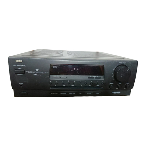
Semco RC100C-2 User manual

A2537-002/01 February 2020 SEMCO Proprietary Information
RC100C-2 SPECTRUM EFFICIENT GROUND RECEIVER
USER’S GUIDE
Systems Engineering & Management Company
1430 Vantage Court
Vista, California 92081
PROPRIETARY INFORMATION
THE INFORMATION CONTAINED IN THIS DOCUMENT CONSTITUTES PROPRIETARY INFORMATION AND INTELLECTUAL PROPERTY
OF SYSTEMS ENGINEERING & MANAGEMENT COMPANY (SEMCO). ACCORDINGLY, THE USER(S) OF THIS INFORMATION AGREE(S)
TO PROTECT THIS INFORMATION TO THE EXTENT THAT THEY WILL PREVENT OTHERS FROM COPYING AND/OR REPRODUCING
THIS INFORMATION, EITHER IN WHOLE OR IN PART, OR MANUFACTURE, PRODUCE, SELL OR LEASE ANY PRODUCT COPIED FROM
OR ESSENTIALLY REPRODUCED FROM THE INFORMATION CONTAINED IN THIS DOCUMENT WITHOUT THE EXPRESSED WRITTEN
APPROVAL OF SYSTEMS ENGINEERING & MANAGEMENT COMPANY.
DISTRIBUTION STATEMENT
DISTRIBUTION OF THIS DOCUMENT IS AUTHORIZED TO U.S. GOVERNMENT AGENCIES, THEIR CONTRACTORS, AND
INTERNATIONAL USERS WHO HAVE PURCHASED SEMCO’S RC100C-2 SPECTRUM EFFICIENT GROUND RECEIVERS UNDER U.S.
EXPORT RULES AND REGULATIONS. THIS PUBLICATION IS PROVIDED AND REQUIRED SOLELY FOR THE USE AND OPERATION OF
THE RC100C-2 TELEMETRY RECEIVER. OTHER REQUESTS FOR THIS DOCUMENT SHALL BE REFERRED DIRECTLY TO SYSTEMS
ENGINEERING AND MANGEMENT COMPANY

A2537-002/01 February 2020 SEMCO Proprietary Information
SAFETY SUMMARY
System Weight and Handling Restrictions - The RC100C-2 Spectrum Efficient Ground Receiver
(SEGR) weighs approximately 15 lbs. (23 kg). Take care in the lifting and installation of each chassis.
When lifting the chassis, always lift from the bottom of the main chassis frame.
Electrical – The RC100C-2 SEGR is designed to operate on 115/230 VAC 50/60 Hz and comply with all
U.S. and International safety codes and regulations required for safe operation and use of commercial
equipment. Use standard and accepted safety practices with respect to operating commercial electrical
equipment at all times to avoid the risk of personal injury or death.
EMI/EMC – The RC100C-2 SEGR complies with all FCC and CE regulations regarding electromagnetic
interference and compatibility. There are no personnel hazards or safety issues with respect to EMI/EMC
when operating the systems.
Exposures to Radio Frequency (RF) Signals – The RC100C-2 SEGR is designed to receive RF signals
from 70 MHz to 5250 MHz at levels of +10 dBm to threshold. These signal levels are well below the
minimum safe exposure levels prescribed by both U.S. and International standards.

A2537-002/01 February 2020 SEMCO Proprietary Information
LIST OF EFFECTIVE PAGES
Page Change Date Page Change Date
All Initial 04/01/2019
All Updates 02/01/2020

A2537-002/01 February 2020 SEMCO Proprietary Information
i
TABLE OF CONTENTS
SECTION TITLE PAGE
SECTION 1 INTRODUCTION 1-1
1.1 Scope 1-1
1.2 Purpose and Description 1-1
SECTION 2 GETTING STARTED 2-1
2.1 Receiver Description 2-1
2.2 Receiver Hardware Installation 2-2
2.2.1 SD Card Interface 2-2
2.3 Receiver Software 2-3
2.4 System Boot and Shutdown 2-4
2.4.1 Navigating the Front Panel LCD Displays and Keypad 2-4
2.4.2 Front Panel Display Screen Settings 2-6
2.4.2.1 Front Panel Display Screen Settings Example 2-6
2.4.3 STATUS Lock/Unlock Indicators 2-9
2.5 Initial SLTS Remote Network Setup 2-9
2.5.1 Changing a Receiver IP Address 2-11
2.5.2 System Naming Feature 2-12
2.6 SLTS Network GUI Design Features 2-13
2.6.1 Toolbar Features 2-13
2.6.1.1 Receiver Settings 2-13
2.6.1.2 System Configuration 2-13
2.6.1.3 Windows 2-15
SECTION 3 HARDWARE I/O 3-1
3.1 Hardware Telemetry I/O 3-1
3.1.1 Single Card Receiver (SCR) Hardware 3-2
3.1.2 Diversity Combiner Hardware 3-2
3.1.3 IF Demodulator Hardware 3-2
3.1.4 Optional Multi-Channel Bit Synchronizer, Frame Synchronizer,
BERT and PN Generator 3-3
3.1.5 TM over I/P Option 3-3
3.1.6 Additional RC100C-2 Hardware 3-3
SECTION 4 TELEMETRY RF RECEIVER OPERATION 4-1
4.1 RF Frequency Settings 4-1
4.1.1 RF Frequency Settings Using Front Panel Controls 4-1
4.1.1.1 Front Panel C/CIF-Band Frequency Settings 4-2
4.1.2 RF Frequency Settings Using the SLTS Program Remote GUI 4-3
4.2 Receiver Signal Strength Indicator (RSSI) 4-4
4.2.1 Front Panel Absolute RSSI Display 4-4
4.2.2 Front Panel Relative RSSI Display 4-4
4.2.3 Front Panel Antenna Signal Strength Display 4-5
4.2.4 Remote GUI RSSI Displays and Settings 4-7
4.3 IF Filter Bandwidth Selection and Control 4-8
4.3.1 Front Panel IF SAW Filter Selection 4-8
4.3.2 Front Panel IF FIR Filter Selection 4-9
4.3.3 Remote GUI IF SAW Filter Selection 4-10
4.3.4 Remote GUI IF FIR Filter Selection 4-10

A2537-002/01 February 2020 SEMCO Proprietary Information
ii
TABLE OF CONTENTS (cont.)
SECTION TITLE PAGE
4.4 Amplitude Modulation (AM) Settings 4-11
4.4.1 Front Panel AM Settings 4-11
4.4.2 Remote GUI AM Settings 4-12
4.5 AGC Settings 4-13
4.5.1 Front Panel AGC Slope and Polarity Selection 4-13
4.5.2 Front Panel AGC Impedance and Time Constant Selection 4-14
4.5.3 Front Panel AGC Zero and AGC Freeze Selection 4-15
4.5.4 Remote GUI AGC Slope and Polarity 4-16
4.5.5 Remote GUI AGC Output Impedance 4-17
4.5.6 Remote GUI AGC Zero 4-17
4.5.7 Remote GUI AGC Time Constant Selection 4-18
4.5.8 Remote GUI AGC Freeze 4-18
4.6 70 MHz RF Input and Playback Feature 4-19
SECTION 5 DIVERSITY COMBINER OPERATION 5-1
5.1 Diversity Combiner Displays and Controls 5-1
5.1.1 Front Panel Combiner Output Mode Selection 5-2
5.1.2 Combiner Output Mode on Remote GUI 5-2
5.1.3 Front Panel Combiner Status Indicators 5-3
5.1.4 Combiner Status Window on Remote GUI 5-3
5.1.5 Combiner “Best Source Select” (BSS) 5-4
5.1.6 Combiner Zero Feature 5-5
5.1.7 Combiner AGC Slope and Polarity 5-6
5.1.8 AGC Output Impedance Selection 5-7
5.1.9 AGC Zero 5-7
SECTION 6 DEMODULATOR AND EMBEDDED BIT SYNCHRONIZER
OPERATION 6-1
6.1 Overview 6-1
6.2 Demodulator Mode Selection 6-1
6.3 Demodulator Data Rate Entry 6-3
6.3.1 QPSK Data Rate Entry 6-6
6.4 Demodulator Output Modes 6-6
6.5 Analog/Digital Baseband Video FIR Filter Bandwidth and Gain
Controls 6-6
6.6 Embedded Bit Synchronizer Features 6-8
6.6.1 Input Code and De-Randomizer 6-8
6.6.2 Clock Phase 6-10
6.6.3 I/Q Interleaving 6-11
6.7 Auto Demodulator Settings 6-12
6.7.1 Auto Loop Bandwidths, Sweep Range and Sweep Rate Settings 6-13
6.8 Additional Advanced Demodulator Settings 6-15
6.8.1 Fast Acquire 6-17
6.8.2 Loop Bandwidth Divider 6-18
6.8.3 FM Sweep 6-19
6.8.4 De-Emphasis and Low Pass Analog Filters 6-20
6.8.5 Modulation Indexing 6-21
6.8.6 Data Quality Metric/Encapsulation (DQM/DQE) 6-23

A2537-002/01 February 2020 SEMCO Proprietary Information
iii
TABLE OF CONTENTS (cont.)
SECTION TITLE PAGE
6.8.7 Adaptive Equalization (AE) 6-26
6.8.8 Low Density Parity Check (LDPC) FEC 6-27
6.8.9 Space Time Coding (STC) 6-31
SECTION 7 BIT SYNC/FRAME SYNC AND BERT OPTION 7-1
7.1 GUI Bit Sync/Frame Sync and BERT Setup and Controls 7-1
SECTION 8 TM OVER I/P 8-1
8.1 Description 8-1
8.2 PCM TM over IP 8-1
8.3 Chapter 10 TM over IP 8-1
8.4 TM over IP Settings and Controls 8-4
8.4.1 Time Source 8-4
8.4.2 Protocol Settings 8-5
8.4.3 Remote IP Addresses 8-6
8.4.4 Data Port 8-7
8.4.5 Data Header 8-7
8.4.6 Input Termination 8-8
8.4.7 Data Buffering 8-9
8.4.8 MTU Size 8-9
8.4.9 Rx Buffers 8-10
8.5 TM over IP Transmission 8-11
ILLUSTRATIONS
FIGURE TITLE PAGE
2-1 RC100C-2 Spectrum Efficient Ground Receiver 2-1
2-2 RC100C-2 Initial Power and Remote (Network) Connections
(LAN and TM over IP) 2-2
2-3 RC100C-2 SEGR Front Panel LCD Displays and Keypad 2-3
2-4 Remote (Network) GUI Displays 2-3
2-5 Front Panel Keypad Controls 2-4
2-6 Front Panel Display Screen Settings 2-6
2-7 CH1 RF Tuner Settings 2-7
2-8 General Settings Display 2-7
2-9 General Status Display 2-7
2-10 Front Panel Display Settings Example 2-8
2-11 Front Panel Display Screen Settings 2-8
2-12 Front Panel Display Settings with Multiple Choice Selection 2-9
2-13 Client and RC100C-2 Network Connections 2-9
2-14 Client SLTS and Lantronix Desktop Icons 2-9
2-15 SLTS Receiver Status Window 2-10
2-16 Receiver IP Address Search 2-10
2-17 Entering Receiver IP Address and Name 2-11

A2537-002/01 February 2020 SEMCO Proprietary Information
iv
ILLUSTRATIONS (cont.)
FIGURE TITLE PAGE
2-18 Changing a Receiver IP Address 2-12
2-19 System Naming Feature 2-13
2-20 Slaving Feature on Remote GUI 2-14
2-21 Slaving Feature on Front Panel 2-14
2-22 System Card Set Selection on Remote GUI 2-15
2-23 AGC Strip Chart Display 2-15
2-24 AGC Data/System Parameters Logging 2-16
2-25 Combiner Zero Feature 2-16
2-26 Combiner Zero Feature on Front Panel/Keypad 2-17
2-27 TM over IP Feature 2-17
2-28 Eye Pattern and Constellation Feature 2-18
2-29 Eye Pattern and Constellation Selection Using Front Panel 2-18
2-30 Save Presets Feature 2-19
2-31 Load Presets Feature 2-20
2-32 Receiver Help Feature 2-20
3-1 RC100C-2 Rear Panel Telemetry I/O 3-1
4-1 RF Frequency Selection (Both CHs) Using Front Panel Displays
and Keypad 4-1
4-2 RF Frequency Selection (single CH) Using Front Panel Displays
and Keypad 4-1
4-3 RF Frequency Selection from the Tuner Menu 4-2
4-4 RF CIF Frequency Selection from the Tuner Menu 4-2
4-5 Remote GUI Frequency Selection 4-3
4-6 Frequency Up/Down Increment Selection on Remote GUI 4-3
4-7 Entering a CIF-Band Frequency on Remote GUI 4-4
4-8 Absolute RSSI Status Display 4-4
4-9 AGC Zero and Relative RSSI Status Settings 4-5
4-10 Antenna Signal Strength and Correction Factor Settings 4-6
4-11 Absolute and Relative Signal Strength Display on Remote GUI 4-7
4-12 Maximum/Average Signal Strength Indicator on Remote GUI 4-7
4-13 Antenna Signal Strength Feature on Remote GUI 4-8
4-14 Front Panel IF SAW Filter Bandwidth Selection 4-9
4-15 IF FIR Filter Bandwidth Selection 4-9
4-16 IF SAW Filter Bandwidth Selection on Remote GUI 4-10
4-17 IF FIR Filter Bandwidth Selection on Remote GUI 4-10
4-18 AM LPF Frequency, Polarity and Impedance Selection Using
Front Panel 4-11
4-19 AM LPF Frequency, Polarity and Impedance Selection Using
Remote GUI 4-12
4-20 AGC Slope and Polarity Selection Using Front Panel 4-13
4-21 AGC Impedance and Time Constant Selection Using Front Panel 4-14
4-22 AGC Zero Using Front Panel 4-15
4-23 AGC Freeze Using Front Panel 4-16
4-24 AGC Slope and Polarity on Remote GUI 4-16
4-25 AGC Output Impedance on Remote GUI 4-17
4-26 AGC Zero Feature on Remote GUI 4-17

A2537-002/01 February 2020 SEMCO Proprietary Information
v
ILLUSTRATIONS (cont.)
FIGURE TITLE PAGE
4-27 AGC Time Constant Selection on Remote GUI 4-18
4-28 AGC Freeze Selection on Remote GUI 4-19
4-29 Attenuator Disable Feature on Remote GUI 4-19
4-30 70 MHz RF (IF) Pre-d and Playback Using Front Panel 4-20
4-31 70 MHz RF (IF) Pre-d and Playback on Remote GUI 4-20
5-1 Front Panel Diversity Combiner Output Mode Selection 5-2
5-2 Diversity Combiner Output Mode on Remote GUI 5-2
5-3 Front Panel Combiner Lock/Unlock Displays 5-3
5-4 Diversity Combiner Status Display on Remote GUI 5-3
5-5 Diversity Combiner Best Source Selection Using Front Panel 5-4
5-6 Diversity Combiner Best Source Selection on Remote GUI 5-4
5-7 Front Panel Combiner Zero Feature 5-5
5-8 Combiner Zero Feature on Remote GUI 5-5
5-9 Front Panel Combiner AGC Slope and Polarity Selection 5-6
5-10 Combiner AGC Slope and Polarity Selection on Remote GUI 5-6
5-11 Combiner AGC Output Impedance Selection on Remote GUI 5-7
5-12 Front Panel Combiner AGC Zero Selection 5-7
5-13 Combiner AGC Zero Feature on Remote GUI 5-8
6-1 Demod Mode Selection Using Front Panel DEMOD Controls 6-2
6-2 Demod Mode Selection Using Front Panel MOD MODE Controls 6-2
6-3 Demod Mode Selection in Individual or Multiple Channels 6-2
6-4 Demodulator Mode Selection on Remote GUI 6-3
6-5 Demodulator Data Rate Selection Using Front Panel Displays
and Keypad 6-3
6-6 Individual Demodulator Data Rate Selection 6-4
6-7 Demod Data Rate Selection from the Demod Menu 6-4
6-8 I and Q Data Rate Entry on Front Panel 6-5
6-9 Data Rate Entry on Remote GUI 6-5
6-10 I and Q Data Rate Entry on Remote GUI 6-5
6-11 Front Panel Video FIR Filter BW Selection 6-6
6-12 Front Panel Analog Video Gain Selection 6-7
6-13 Video FIR Filter Bandwidth and Gain Selection on Remote GUI 6-8
6-14 Enabling the Bit Sync De-Randomizer Using the Front Panel 6-9
6-15 Selecting Bit Sync De-Randomizer Input Codes Using the
Front Panel 6-9
6-16 Remote GUI De-Randomizer and Input Code Selection 6-10
6-17 Embedded Bit Sync Clock Phase Settings Using Front Panel 6-10
6-18 Remote GUI Embedded Bit Sync Clock Phase Settings 6-11
6-19 Front Panel I/Q Interleaving Selection 6-11
6-20 I/Q Interleaving Selection on Remote GUI 6-12
6-21 Front Panel AUTO Bandwidth and Sweep Settings 6-14
6-22 AUTO and Manual Bandwidth and Sweep on Remote GUI 6-15
6-23 Front Panel Fast Acquire Feature 6-17
6-24 Fast Acquire on Remote GUI 6-18
6-25 Front Panel Loop BW Divider Settings 6-18
6-26 Loop BW Divider on Remote GUI 6-19

A2537-002/01 February 2020 SEMCO Proprietary Information
vi
ILLUSTRATIONS (cont.)
FIGURE TITLE PAGE
6-27 Front Panel FM Sweep Settings 6-19
6-28 FM Sweep on Remote GUI 6-20
6-29 Front Panel Video De-Emphasis and Low Pass Filter Setting 6-20
6-30 Video De-Emphasis Low Pass Filter Settings on Remote GUI 6-21
6-31 Front Panel Auto Modulation Index Settings 6-22
6-32 Front Panel Manual Modulation Index Settings 6-22
6-33 Modulation Indexing Settings on Remote GUI 6-23
6-34 Encapsulation Structure 6-24
6-35 DQM ON/OFF and Frame Size Using Front Panel LCD/Keypad 6-25
6-36 DQM Frame Size Using Front Panel LCDs and Keypad 6-25
6-37 DQM Setup on Remote GUI 6-26
6-38 Front Panel AE Selection 6-26
6-39 AE Selection on Remote GUI 6-27
6-40 SOQPSK-LDPC Mode Selection Using Front Panel 6-28
6-41 SOQPSK-LDPC Mode Selection Using Front Panel Using
MOD MODE Controls 6-28
6-42 SOQPSK-LDPC Selection in Individual or Multiple Channels 6-28
6-43 Front Panel SOQPSK-LDPC Settings 6-29
6-44 SOQPSK-LDPC Settings on Remote GUI 6-30
7-1 Bit Sync/Frame Sync/BERT Window 7-1
8-1 TM over IP Block Diagram 8-1
8-2 General Chapter 10 Packet Structure 8-3
8-3 General Time Packet 8-3
8-4 TM over IP Setup on Remote GUI 8-4
8-5 IP Address, Netmask and Gateway Settings on Remote GUI 8-4
8-6 TM over IP Channel Settings on Remote GUI 8-5
8-7 Protocol Settings on Remote GUI 8-6
8-8 Remote IP Address Entry on Remote GUI 8-6
8-9 Data Port Entry on Remote GUI 8-7
8-10 Data Header Selection on Remote GUI 8-8
8-11 Input Termination Selection on Remote GUI 8-8
8-12 Data Buffering Selection on Remote GUI 8-9
8-13 MTU Size Entry on Remote GUI 8-10
8-14 Rx Buffer Entry on Remote GUI 8-10
8-15 TM over IP Transmission on Remote GUI 8-11
TABLES
TABLE TITLE PAGE
3-1 RC100C-2 System I/O 3-1
6-1 Demodulator Modes and Features 6-1
6-2 LR, DQM and Correlating BEP Values 6-23
8-1 Chapter 10 Data Formats Supported by RC100C-2 8-2

A2537-002/01 February 2020 1-1 SEMCO Proprietary Information
SECTION 1 - INTRODUCTION
1.1 Scope
This User’s Guide addresses the installation and operation of SEMCO’s RC100C-2 Spectrum Efficient
Ground Receiver (SEGR), which is used for telemetry data reception and antenna tracking functions
related to aircraft, missiles and weapon system testing.
1.2 Purpose and Description
This User’s Guide provides detailed information to allow for installation and operation of the RC100C-2
SEGR.
Section 2, Getting Started briefly describes and lists the standard and optional hardware features of the
SEMCO RC100C-2 SEGR and describes how to install and apply power. Section 2 also walks the user
through the features and use of the front panel LCD displays and keypad, as well as installation and use
of the System Level Telemetry Software (SLTS) program for RC100C-2 remote (network) operation via
Ethernet.
Section 3, Hardware I/O and Software Controls describes the RC100C-2 hardware I/O interface and
provides instructions for setting up receiver operation and control. The standardized hardware I/O
description facilitates installation of the RC100C-2 in a typical Telemetry Ground Station.
Section 4, Telemetry RF Receiver Operation provides a description and instructions for RC100C-2 set-
up, operation and status monitoring of RF Receiver and Antenna Tracking features, including RF Tuning
and down-conversion, 70 MHz linear IF signal distribution, Signal Strength monitoring, IF Filtering,
Automatic Frequency Control (AFC), Amplitude Modulation (AM) and Automatic Gain Control (AGC).
Section 5, Diversity Combiner Operation provides a description and instructions for set-up, operation
and status monitoring of the RC100C-2 Diversity Combiner, including but not limited to Combiner modes,
Best Source Selection feature, AGC Zero, CH1/CH2 balancing feature and combiner AM and AGC.
Section 6, Multi-Mode Demodulator Operation provides a description and instructions pertaining to set-
up, operation and status monitoring of the RC100C-2 Demodulator feature, including but not limited to the
several demodulator formats and respective set-up parameters, the embedded bit synchronizer and de-
randomizer feature, and various additional optional features such as Adaptive Equalization (AE), Data
Quality Metrics (DQM), Space Time Coding (STC), Low Density Parity Check (LDPC), Viterbi Forward
Error Correction (FEC) and Turbo FEC. There is a general description of each option herein, and specific
procedures for set-up and use for more frequently used options. Specific procedures for set-up and use of
some options are provided as an addendum to this manual when the user purchases these options.
Section 7, Multi-Channel Bit Synchronizer/Frame Synchronizer and BERT Option provides a
description and instructions pertaining to set-up, operation and status monitoring of a multi-channel
channel Bit Sync/Frame Sync/BERT option as an addition to the embedded bit syncs and de-randomizers
in each of the demodulator channels. This option has user-selectable internal and external input switching,
programmable Frame Sync, BERT and PN Generator.
Section 8, TM over IP Option, provides a description of the embedded receiver TM over IP interface,
which supports multiple IRIG standard telemetry data formats, including DMQ/DQE interfaces and user
specified custom interfaces. The main user interface is the IRIG formats, which are broken down into two
main interfaces: PCM data Interfaces and IRIG Chapter 10 Interfaces.

A2537-002/01 February 2020 2-1 SEMCO Proprietary Information
SECTION 2 – GETTING STARTED
2.1 Receiver Description
SEMCO’s RC100C-2 Spectrum Efficient Ground Receiver (SEGR) is a 1U rack-mount dual channel
telemetry receiver combiner system with both local and remote (network) control (Figure 2-1). The
RC100C-2 design provides the most advanced telemetry receiver platform features and performance while
eliminating IA compliance issues. In addition to the standard and optional features listed below, the
RC100C-2 design incorporates a unique feature that makes the system invulnerable to malicious access
or control of its ARM processors. A Serial to Ethernet converter with SSH Secure Protocol is used to
convert Ethernet TCP/IP packets to RS232 serial data signals and vice versa for bidirectional
communication.
This design provides for three key advantages. First, acting as a buffer, any scan of the external Ethernet
port will not reveal the internal processor connections. Secondly, malicious access or control of the ARM
processors is eliminated by insertion of this buffer. This buffer is analogous to a DMZ (demilitarized zone)
in a network router. Last, but not least, local control and display functionality is retained.
Figure 2-1
RC100C-2 Spectrum Efficient Ground Receiver
Standard RC100C-2 features include:
A. Fully IA Compliant Operational Configuration, with buffered ARM Processor design that precludes
the ability to externally access the processors
B. Multi-Band RF Tuning (70 MHz, 200-1150 MHz, 1415-2485 MHz and 4400-5250 MHz)
C. 28 IF SAW Filters (14 IFBW values between 300 kHz and 40 MHz) and 15 selectable IF FIR Filters
that are presented to the user as a function of data rate input and demodulator format. An Auto IF
SAW and FIR filter feature is also provided.
D. 15 Baseband FIR Filters (2 kHz to 18.7 MHz + Bypass) that are presented to the user as a function
of data rate input and demodulator format. An Auto IF SAW and FIR filter feature is also provided.
E. 3 multi-mode demodulators (PCM/FM PM, BPSK, QPSK, A/U/QPSK, IRIG 106-17 Tier 0 Trellis
FM, Tier I SOQPSK-TG and Tier II Multi-h CPM)
F. 4 baseband analog and digital video outputs per channel (2 analog, 1 Clock and 1 Data)
G. Embedded Bit Synchronizers with a de-randomizer in each demodulator
H. PN Pattern Generator

A2537-002/01 February 2020 2-2 SEMCO Proprietary Information
I. Data Quality Encapsulation/Metrics (DQE/DQM) for use with external Best Source Selectors
J. Adaptive Equalization (AE)
K. SOQPSK Low Density Parity Check (LDPC)
L. SOQPSK Space Time Coding (STC)
M. Scalable AGC outputs (+/- 10, 20 and 50 dB/V per channel) and AM antenna tracking outputs
(CH1/2 and Combiner)
N. Eye Pattern, Constellation and Spectral Sweep displays for each installed demodulator
O. 4 LCD front panel displays and keypad
P. Local GUI Display/Keyboard/Mouse interface and control (USB and HDMI) and Remote control
via Ethernet
Q. A 70 MHz Tape Playback feature (CH1 and CH2)
Optional RC100C-2 features include:
A. Additional demodulation modes (PM/PSK Subcarrier, FM/FM Sub-carrier, GMSK, Coherent AM
and Spread Spectrum (SS-UQPSK, SQPN) demodulation
B. Multi-Channel Embedded Stand-Alone Bit Sync/Frame Sync/BERT with selectable internal and
external switching
C. 3 Channel CH10/IRIG 218 TM over I/P
D. Viterbi Forward Error Correction (FEC)
E. Turbo Coding FEC
2.2 Receiver Hardware Installation
Ensure safe system installation for operation (i.e., secured in the equipment rack or safely positioned on a
non-slip work surface that can support the system size and weight).
Figure 2-2 illustrates the RC100C-2 front panel displays and keypad controls, as well as rear panel I/O
with respect to AC power, local display/keyboard/mouse interface (USB and HDMI) and remote software
communications (LAN and TM over IP) via Ethernet. Note: Local GUI control via USB and HDMI is used
principally as a trouble-shooting tool and not for receiver mission support.
Figure 2-2
RC100C-2 Initial Power and Remote (Network) Connections (LAN and TM over IP)
2.2.1 SD Card Interface
Referring to Figure 2-2, the RC100C-2 provides a front panel dual SD card interface for software and
firmware installation and upgrades without the need to remove the receiver from its rack enclosure. This
front panel interface is a removable access door located as shown.
Power Input
Ethernet
TM over IP
SD Card Access Door
Local GUI Interface

A2537-002/01 February 2020 2-3 SEMCO Proprietary Information
2.3 Receiver Software
SEMCO-developed software is used for front panel LCD/keypad displays and control (Figure 2-3). All
system functions and set-up controls are by remote keyboard entry or via the front panel LCD displays
and keypad. System status is via display indicators (numerical readouts and bar graphs) on both the
remote GUI display and front panel LCD displays.
Figure 2-3
RC100C-2 SEGR Front Panel LCD Displays and Keypad
SEMCO-developed System Level Telemetry Software (SLTS) program software controls and displays
are shown in Figure 2-4. The remote GUI and front panel keypad controls/displays provide for all
required receiver control and status monitoring.
Figure 2-4
Remote (Network) GUI Displays
SLTS Remote (network) Status and Receiver Control Panel GUI

A2537-002/01 February 2020 2-4 SEMCO Proprietary Information
The SLTS interface with the RC100C-2 embedded Linux ARM processor is designed for local operation
via RC100C-2 HDMI display/USB interface and/or remotely controlled via Ethernet.
SEMCO receivers contain a Low-Level Interface Software (LLIS), which provides a server interface to the
receiver hardware in both SEMCO Windows & Linux based platforms. The LLIS server provides a platform
that allows users to develop custom receiver remote software without needing technical knowledge of the
receiver hardware. As an example, the LLIS server is very similar to the USAF STRCI server described in
STRCI Version 4.2.
The STRCI JSON interface is an application layer to the LLIS server and resides on the internal remote
SBC. The JSON messages interface to the LLIS using a messages dictionary. This provides a low
overhead streamlined remote interface that leverages the existing receiver remote server.
2.4 System Boot and Shutdown
Start the RC100C-2 by depressing the red Power button located on the front panel. In approximately 45
seconds, the “auto-boot” process enables the front panel LCD displays previously shown in Figure 2-3.
Receiver Shutdown is accomplished by simply pressing the red Power Button on the front panel.
2.4.1 Navigating the Front Panel LCD Displays and Keypad
The front panel keypad is depicted in Figure 2-5.
Figure 2-5
Front Panel Keypad Controls
The square FUNCTION buttons are described as follows:
A. FREQ - Sets the frequency of both Tuners (default) or CH1 and CH2 individually
B. TUNER - Menu to set any parameter of an individual RF Tuner
C. PRESET - Menu to LOAD or STORE a PRESET
D. MOD MODE - Menu to select the demodulation mode of all (default) demodulators or individual CH1,
CH2, and Combiner demodulators
E. DEMOD - Menu to set any parameter of an individual channel demodulator

A2537-002/01 February 2020 2-5 SEMCO Proprietary Information
F. DISPLAY - Menu to select what is to be displayed on any of the 4 display screens. The far right screen
next to the keypad is the default display.
G. DATA RATE - Menu to enter the demodulator data rate for ALL (default) demods or CH1, CH2 and
Combiner individually. Data rate is entered in kbps, which then switches to Mbps when the data rate
value entered is 1000.0 kbps or greater.
H. COMB MODE - Menu to set any parameter of the Combiner
I. MENU - Main Menu showing receiver information (Name, ID channels, serial numbers etc) in addition
to Slaving mode, 10MHz Reference Int/Ext selection and TMoIP. The following example is provided
as to all menu settings:
Name: RC100
Type: RC100 (Dual Channel Receiver Combiner)
ID: Receiver Serial Number (e.g. 17010-0001)
Channels: 2R 1C 3D (2 receiver channels, 1 combiner channel and 3 demodulator channels)
Card List: 2R 1C 3D (2 receiver channels, 1 combiner channel and 3 demodulator channels)
Version: 1.06.0 (Software Version)
Slaving None (will show None, Diversity or Frequency depending on user selection)
The circular Menu Navigation and Entry buttons are described as follows:
The Navigation buttons and Numerical Entry buttons have a dual overlapping function. The keypad has
numerical buttons from 0 through 9, a DELETE button which serves as a backspace function and an
ENTER button to submit the entered/selected numerical value. Overlapping the keypad in blue colors are
the UP (2), DOWN (8), LEFT (4), and RIGHT (6) arrows, a SELECT (5) button and an EXIT (DELETE)
button.
To start navigation, first select a desired FUNCTION from one of the square buttons. The far-right display
next to the keypad will change to the function selected. In certain cases (TUNER, MOD MODE, DEMOD,
and COMB MODE), there is an option to change parameters for ALL, CH1, CH2 or Combiner. In certain
cases, there is also a < and > in the top title bar of the display, and the CH1, CH2 or Combiner selection
will be displayed (i.e. <Ch1>). To change this selection, use the LEFT (4) and RIGHT (6) arrows to move
between the selections and press ENTER when the desired setting is displayed.
For FREQ and DATA RATE functions, the display will show all selections highlighted in blue in the center
of the screen. To change the parameter for an individual channel, press the function button again. The
individual selection will be highlighted in blue while the other(s) will be deselected. Press the function again
to toggle to the other selection(s). After moving through the selections, the final function press will exit the
menu.
In the individual menus, there are many parameters in a list mode signified by a
∧
and
∨
above and below
the list. Use the UP (2) and DOWN (8) arrow to scroll up and down the menu, and the selected parameter
will be highlighted in bright blue. To change that parameter, press ENTER or SELECT (5), and the
parameter will be highlighted in a bright magenta color.
Once the desired parameter is selected, use the UP (2) and DOWN (8) arrow again to scroll though the
available selections for the selected parameter. Depending on the parameter, there may be from 2 to as
many as 15 available selections. For numerical values, enter the number using the keypad. In all cases
pressing ENTER will program the selected value to the receiver. Pressing the EXIT (DELETE) button will
also exit the current menu.

A2537-002/01 February 2020 2-6 SEMCO Proprietary Information
When entering numerical values, the menu will react differently when entering illegal values. For FREQ,
an invalid value will do nothing when pressing ENTER. For DATA RATE, an invalid value will do nothing
and exits the menu.
For parameters within a function menu, attempting to submit an invalid value will do nothing while keeping
the parameter highlighted in bright magenta. In all cases, use the EXIT (DELETE) button and attempt to
re-enter a valid value.
2.4.2 Front Panel Display Screen Settings
The user has the choice of configuring the 4 displays with the information of their choice. Pressing the
DISPLAY function/button provides a scrolling list in the far-right display (closest to the keypad) that lists all
options for any of the 4 display screens. When the DISPLAY button is pressed, the top title bar will be
highlighted in a bright magenta color.
To choose a display other than the far-right display for desired settings, use the LEFT (4) and RIGHT (6)
arrow to move the bright magenta top title bar to the display of choice. Then, using the far-right display,
scroll UP (2) and DOWN (8) arrows until the setting desired is highlighted. Press ENTER or SELECT (5)
and the selected setting will appear in the display of choice. Repeat the steps above for the other front
panel displays as desired.
2.4.2.1 Front Panel Display Screen Settings Example
The following example illustrates setting up the 4 front panel displays. In this example, CH1 RF Tuner
Settings are going to be set-up on the far-left display. Going left-to right, CH 2 RF Tuner Settings are
going to be set-up on the next display, General Settings for CH1, CH2 and the Combiner are going to
be set-up on the next display and General Status is going to be set-up on the last (far right) display.
A. Step 1 - Select DISPLAY on the keypad and verify the far-right display is as shown in Figure 2-6.
B. Step 2 - Using the DOWN (8) arrow, scroll to Tuner Settings and press ENTER. Then use the DOWN
(8) arrow to select Ch1 (highlighted in blue) as shown in Figure 2-6.
Figure 2-6
Front Panel Display Screen Settings

A2537-002/01 February 2020 2-7 SEMCO Proprietary Information
C. Step 3 - Using the LEFT (4) arrow, move the bright magenta top title bar to the far-left display and
press ENTER. The display will show a green Ch1 Synth Lock and display as depicted in Figure 2-7.
Figure 2-7
CH1 RF Tuner Settings
D. Step 4 - Repeat Steps 2 and 3 for a green Ch2 RF Synth Lock display in the second-from-the-left
display.
E. Step 5 - Select DISPLAY on the keypad and verify the far-right display is as previously shown in
Figure 2-6.
F. Step 6 - Using the DOWN (8) arrow, scroll to General Settings and press ENTER.
G. Step 7 - Using the LEFT (4) arrow, move the bright magenta top title bar to the third-from-left display
and press ENTER to enable a green General Settings display as depicted in Figure 2-8.
Figure 2-8
General Settings Display
H. Step 8 - Select DISPLAY on the keypad and verify the far-right display is as previously shown in
Figure 2-6.
I. Step 9 - Using the DOWN (8) arrow, scroll to General Status and press ENTER. The far-right display
will now show the general status of the Combiner, CH1 and CH2 as shown in Figure 2-9.
Figure 2-9
General Status Display

A2537-002/01 February 2020 2-8 SEMCO Proprietary Information
Figure 2-10 shows the 4 front panel LCD displays resulting from successful completion of steps 1 thru 9.
The 2 far left displays show CH1 and CH2 RF Tuner settings and a green Ch1 Synth Lock and Ch2 Synth
Lock indication.
The 3rd from the left display is the General Settings display, showing the main CH1, CH2 and Combiner
settings (Ch1, Ch2 and CMB) with respect to Frequency, Demodulation Format and Data Rate. The far-
right display provides General Status of CH1, CH2 and the Combiner channel.
Figure 2-10
Front Panel Display Settings Example
Figure 2-11 shows all available display selections available, with the corresponding screen display
associated with each selection. Steps 1 thru 9 above should be followed to select and position the desired
settings on each of the 4 front panel displays.
Figure 2-11
Front Panel Display Screen Settings

A2537-002/01 February 2020 2-9 SEMCO Proprietary Information
As previously shown in Steps 2 and 3 above, there are cases where there are multiple choices, such as
which Tuner or Demod to display, and a pop-up will appear after pressing ENTER for choosing between
CH1, CH2 and/or Combiner. The operator then uses the UP (2) and DOWN (8) arrows to highlight the
desired selection and press ENTER. Figure 2-12 provides examples of screens with multiple choices.
Figure 2-12
Front Panel Display Settings with Multiple Choice Selection
2.4.3 STATUS Lock/Unlock Indicators
Status LOCK and UNLOCK indicators are provided on the front panel displays for the RF Synthesizer
(Tuner), Combiner, Demodulator and Bit Synchronizer Demodulator.
A. Top bar in Tuner Status displays is GREEN for Synthesizer LOCK and RED for UNLOCK.
B. Top Bar in Combiner Status displays is GREEN for Combiner LOCK and RED for UNLOCK.
C. Top Bar in Demod Status displays is GREEN for Demodulator and Bit Synchronizer LOCK, YELLOW
with Demodulator only LOCK, and RED for UNLOCK.
2.5 Initial SLTS Remote Network Setup
Figure 2-13 shows Client and RC100C-2 network connections. The RC100C-2 has 2 RJ45 Ethernet
connections on the rear panel and network control is labeled LAN. Client OS is Win 7/10.
Figure 2-13
Client and RC100C-2 Network Connections
Step 1 - Install the SLTS and Lantronix software application on the Client. The SEMCO SLTS and Lantronix
Device Installer icons appear on the Client Desktop as shown in Figure 2-14.
Figure 2-14
Client SLTS and Lantronix Desktop Icons
Ethernet
Hub
RC100C
RC100C
…Additional RC100C Receivers as required
Client

A2537-002/01 February 2020 2-10 SEMCO Proprietary Information
Step 2 - Open the SLTS software. If the IP addresses of the connected RC100C-2 receivers are already
recognized by the SLTS program, then the Receiver Status Window shown in Figure 2-15 will appear for
each connected RC100C-2, and the connected RC100C-2 IP addresses will be listed under IP address.
As an example, Figure 2-15 shows one RC100C-2 connected with an IP address of 169.254.10.131.
Figure 2-15
SLTS Receiver Status Window
Step 3 – If the Receiver Status Screen does not display each receiver’s IP address and status, then open
the Lantronix DeviceInstaller and it will search for the IP address of all attached receivers. This is
accomplished by double-clicking on Lantronix Devices, PremierWave and then PremierWave SE1000
(256MB)-firmware as shown in Figure 2-16.
The IP addresses of each connected RC100C-2 will be listed.
Figure 2-16
Receiver IP Address Search
Step 4 – Copy down all listed receiver IP addresses. Open the SLTS Program and click on Edit, System
Address List and Add as shown in Figure 2-17.
In the Create System Connection Setup window, enter each connected receiver IP address by typing in
each IP address in the window below IP Address as shown. It is also a good time to edit system Name
by typing in information that will tie a particular receiver S/N or location to its IP address. In the Figure 2-
17 example the receiver S/N DEMO-1907 has been used. Note that there is a “0” entered preceding
DEMO-1907 (0DEMO-1907). Typing in a numerical sequence (i.e., 0, 1, 2, 3 etc.) in this manner ensures
that all networked receivers will be listed in that order. Otherwise, they will be listed in the order that they
come on-line in a network.
Click on Create after the receiver’s IP address and desired Name has been entered. Repeat this step for
each receiver IP address.
Table of contents
