Sencon BCM500 User manual

© 1993, 1995, 2000 2016 Sencon Incorporated Page 1 BCM500/2x7 Bodymaker System
BCM500 BODYMAKER CONTROL MODULE
When using any of the non-smart short can sensors
247, 267, 287, 487
INSTRUCTION MANUAL
RELEASE 1.2

© 1993, 1995, 2000 2016 Sencon Incorporated Page 2 BCM500/2x7 Bodymaker System
DESCRIPTION
BCM 500 BODYMAKER CONTROL MODULE
The BCM500 is an expansion of the capabilities of the 387-S1 Bodymaker Sensor System. The module
supports the following functions:
•short can and tear-off detection
•dome jam detection
•airstrip function.
This manual explains how to configure a BCM500 for use with a ‘non-smart’ 2x7 and 487 short can sensor,
this includes the 247, 267, 287 and 487 series sensors.
The BCM500 receives Air Strip, Backstop and Short Can timing signals from the Autotech or other type of
timing switch, together with signals from the Short Can and Dome Jam Sensors. It provides outputs
direct to the Clutch and Airstrip Solenoids, together with outputs to the PLC to indicate:
•Loss of Calibration - only when using a Smart Sensor for Aluminium Cans
•Short Can - a marginally short can
•Misfeed/Tear Off - no can was made at all or it was a very short can
•Dome Jam
•Can Jam or Short Can Sensor Fault - an output was detected from the Short Can Sensor at a time
when no can should have been present. (The Can Jam condition can only be detected when
using a “non-smart” sensor)
The BCM500 must be correctly set according to the type of sensor in use (PNP or NPN) and various other
parameters. These are set on links inside the module, details are given in this manual. In addition to this
the BCM500 has to be set according to the type of Short Can sensor connected, this may be:
•387 "Smart" Sensor for Aluminium on Carbide or steel
•487 “non-smart” sensor for Aluminium on Carbide
•287 "non-smart" sensor for Aluminium on Carbide
•267 "non-smart" sensor for Steel on Carbide.
•247 "non-smart" sensor for Aluminium on steel.
This setting can only be altered by using software available from Sencon, which communicates with the
BCM500 via its serial port.
The Bodymaker Control Module offers two modes for stopping the Bodymaker:
•Immediate stop mode stops the machine when a can defect is detected. The module immediately
opens two transistor switches that can interrupt up to 2 Amperes at 24 Volts when a defect is
detected.
•Timed stop mode synchronizes stopping the machine with the leading edge of the backstop window.

© 1993, 1995, 2000 2016 Sencon Incorporated Page 3 BCM500/2x7 Bodymaker System
DIMENSIONS
BCM500 Module
BCM500 Module Mounting
The BCM500 controller is designed to be mounted in a control
cabinet protected from moisture and hydraulic fluids. The unit
may be mounted using a 35 mm DIN rail or with two fasteners.
Recommended screw fasteners are #8 or M4.

© 1993, 1995, 2000 2016 Sencon Incorporated Page 4 BCM500/2x7 Bodymaker System
SPECIFICATIONS
Input Supply Voltage
Module
24 VDC ±2.4 VDC
Input Supply Current
Module
400 mA Plus Load Current at 24 VDC
Module Signal
Inputs
Configuration
Source (Active High) or Sink (Active Low)
Voltage Range
Minimum
-0.7 VDC
Maximum
Input Supply Voltage Value
Threshold
High State
55% of Input Supply Voltage
Low State
45% of Input Supply Voltage
Impedance
5 kΩ
Allowable Leakage
400 μA
Storage Temperature
Module
- 40° F to +185° F [- 40° C to +86° C]
Operating Temperature
Module
+32° F to +158° F [0° C to +70° C]
Environment
Module
Requires mounting in a NEMA 12 or equivalent control cabinet,
removed from direct contact with moisture or hydraulic fluids.
GENERAL CHARACTERISTICS
Weight
1 lb. [450 g]
Case
Polycarbonate
Termination
Screw terminals recessed to protect against accidental contact.
MODULE SOLID STATE SWITCH OUTPUT CHARACTERISTICS
Maximum Load
40 mA, Typical ON resistance at 25 mA is 25 Ω
500 mW maximum power through the switch
Voltage Range
0 to 240 VAC (peak) or 0 to 240 VDC
Output Type
Bi-directional, isolated solid state switches.
Output Configuration
Suitable for DC source, DC sink, or AC.
MODULE TRANSISTOR SWITCH OUTPUT CHARACTERISTICS
Maximum Load
2 A DC Resistive/Inductive
Voltage Range
-0.7 VDC to 30 VDC
Voltage Drop
0.6 VDC at 1 A, 0.9 VDC at 2 A
Short Circuit Protection
Momentary (10 seconds)
Output State
Determined by the operating state. Refer to the `Operation' section of this TDS for details.
Output Configuration
Optically Isolated FET Transistor Switch, Conductive in the Active State

© 1993, 1995, 2000 2016 Sencon Incorporated Page 5 BCM500/2x7 Bodymaker System
INSTALLATION
MECHANICAL INSTALLATION
ELECTRICAL INSTALLATION
The inputs and outputs to the BCM500 are shown here. Electrical connection is made to the unit with
screw terminals. The terminals are recessed to reduce the chances of accidentally contacting them.
+VS
0VS
Sensor Output
09-487-00
Red
Black
White
11-487-00
Brown
Blue
Black
9-247-03
9-267-03
9-287-03/33/53/63
Red
Black
Green – source
11-247-03
11-267-03
11-287-03/33/53/63
Brown
Blue
Black – source
The 0V, 0VI, and 0VS terminals are common to each other.
However, do not use the 0VI or 0VS terminals for power loads. They are intended for low-level signals
only.
The outputs are optically isolated from the supply voltage and the inputs.
The COM terminal can be connected to an AC lead, to a DC lead, to the 0V terminal, or to the +VIN
terminal.

© 1993, 1995, 2000 2016 Sencon Incorporated Page 6 BCM500/2x7 Bodymaker System
2x7 Sensor Interconnection
Make sure to seat fully and tighten the cable connector on 11 series sensors. Also install and clamp
the hydraulic tubing over the fitting. Otherwise, liquid may infiltrate the connector and degrade
performance.
DC Signal Inputs
Configure the input signals as shown in the diagram below. Settings are made with mini-jumpers
accessible under the top cover of the unit. Remove the top cover by inserting a flat screwdriver
blade in the slot shown and rotating the blade to `pop' the cover off. This operation MUST be done
with power off to avoid damaging the unit.
Note: Alternative input setups are possible. Consult the factory for details.
If an input is active high, the flow of current at the input terminal is ON, and no current flow at the
input terminal is OFF. The reverse is true if an input is active low. The transition from OFF to ON is
the leading edge of the signal. The transition from ON to OFF is the trailing edge of the signal.

© 1993, 1995, 2000 2016 Sencon Incorporated Page 7 BCM500/2x7 Bodymaker System
Solid State Switch Outputs
These outputs are optically isolated from the supply voltage. Therefore, the COM terminal is floating and
can be connected to any reference that falls within the specified voltage range.
FET Transistor Switch Outputs
There are three FET transistor switches for control of the Bodymaker clutch/brake solenoids and the air
strip solenoid. The contacts are FET transistors that are optically isolated from the internal power supply.
IMPORTANT SAFETY NOTICE - The transistor switches provided with this unit must not be the only
means of controlling the Bodymaker clutch mechanism. Good design practice dictates the use of
safety lockouts on any device that starts and stops automatically that can cause personal injury to
operating or maintenance personnel. The BCM500 must be used only with industry approved
safety lockout contacts, otherwise serious personal injury may result.

OPERATION
MODULE SIGNAL INPUTS
The Bodymaker Sensor System requires the ten inputs described here. These inputs are not optically
isolated from the BCM500 internal power supply.
Input
Description
SCT
The Short Can Timing window is active when the punch is in position for sensing. The rising edge of the
window signal corresponds to the can body trimline.
NOTE: THIS INPUT IS ALWAYS ACTIVE LOW.
BST
The Back Stop Timing window allows a synchronous stop of the machine. The clutch outputs open on the
falling edge of this signal in the Timed Stop mode.
NOTE: THIS INPUT IS ALWAYS ACTIVE LOW.
AST
The Air Strip Timing window is active during the stroke for the period that allows the can to be blown off the
punch.
NOTE: THIS INPUT IS ALWAYS ACTIVE HIGH.
DJI
The BCM500 checks the Dome Jam Input from the end of the SCT window until the end of the AST or BST
windows. Therefore, either of these windows must be active just past 180 degrees of the machine cycle to
detect a dome jam.
RES
The Reset/Override input clears all faults and closes the appropriate output switches. While the
Reset/Override input is active, no tear-offs, short cans, or dome jams are detected. After a fault, this input
must be activated before restarting the Bodymaker. The CE input must also be active to close any output
driver switch.
CE
The Clutch Enable Input must be active to initiate a machine stroke. The Bodymaker stops immediately when
the CE changes from active to inactive in the Immediate Stop mode. The Bodymaker stops on the leading edge
of the BST window in the Timed Stop mode.
ASE
The Air Strip Enable must be active to close the air strip switch.
CAL
This input is only used for 387 sensors.
The Calibrate input sends a calibrate command to the sensor and checks for a good calibration output from the
sensor. When a good calibration is detected by the module, the calibrate output closes. This takes at least
four cycles. The Calibrate input must be shutoff before the cup feed turns on. An active Calibrate input puts
the module in the Reset/Override mode.
I/T
The Immediate Stop mode stops the machine immediately by opening transistor switches CO1 and CO2 when a
defect is detected. The Timed Stop mode synchronizes the operation of CO1 and CO2 with the leading edge of
the BST window.
SIN
The Sensor input is for a source or push-pull only sensor output. This input from the sensor is normally ON
(high) during the SCT window.

SOLID STATE SWITCH LOGIC OUTPUTS
The Bodymaker Control Module has four solid state switch outputs. These outputs are bidirectional and
isolated from the BCM500 internal power supply. They can be wired for DC source, DC sink, and AC.
These outputs are rated for 40 mA (maximum) at up to 240 VAC (peak) or 240 VDC.
Input
Description
CAL
The Calibrate output is ON (current flow allowed) after the sensor has been calibrated and remains ON while
the sensor calibration is good. This output is only used for 387 sensors.
DJO
The Dome Jam Output is OFF (no current flow allowed) after a dome jam is detected and remains OFF until a
reset signal is applied.
SC2
The SC2 output is OFF (no current flow allowed) after a short can is detected and remains OFF until a reset
signal is applied.
SC1
The SC1 output is OFF (no current flow allowed) after a tearoff is detected and remains OFF until a reset signal
is applied.
Note: If the sensor fails, or a can jam is detected, all of the logic outputs turn OFF.
The BCM500 will detect a can jam if the Short Can sensor is still seeing metal by the time all three timing
signals it receives have completed "one cycle". “One cycle” is deemed to begin when the first timing
signal becomes active and ends when the last timing signal becomes inactive. This cycle is therefore
entirely dependent upon the timing set-up of each bodymaker.
The system cannot distinguish between a Can Jam and a faulty Short Can sensor which has failed with its
output turned on
If the sensor is not faulty, and there is no can jam, the apparent fault can be caused if the can
remains held in the Dome Station by excessive Strip Air pressure or duration, or by the take away
conveyor timing if it is slightly late. One remedy for this which can be applied with caution is to
increase the time allowed for the can to be taken away before such a fault is detected by lengthening
the Backstop timing windows. When a Can Jam or Short Can Sensor fault is detected this is indicated
by all the outputs "Short Can," "Misfeed/Tear Off," "Dome Jam" and "Calibration" switching off
together.
TRANSISTOR SWITCH CLUTCH/SOLENOID CONTROL OUTPUTS
The driver outputs are FET transistor switches and are isolated from the supply power. The rated load is
two amperes maximum at 30 volts. Polarity must be observed.
Input
Description
DR4
The DR4 driver is currently not in use. This is reserved for future expansion.
ASO
The Air Strip Output is closed while the AST window and the ASE inputs are active.
CO2
Clutch Output 2 is closed while the CE input is active and the RES has cleared any faults. It remains closed until
the CE input goes inactive or a fault occurs. When a fault occurs, the output opens immediately (Immediate
Stop) or opens synchronized with the leading edge of the BST window (Timed Stop).
CO1
Clutch Output 1 follows CO2.

FULL CAN CHECK AND TRIMLINE CHECK
The system normally does a full can check when it is evaluating a can for defects. The sensor normally
profiles the punch at various points during the SCT window. Trimline check differs from this in that only
the trimline is evaluated. The system can be forced into trimline check with the Trimline Mode Select
jumper.
The system logic output SC1 indicates a tearoff when it occurs, even with the system in trimline check.
This signal provides information about where the tearoff occurred along the punch. However, the clutch
outputs CO1 and CO2 open only if the trimline check fails.
POWER UP
The BCM500 must receive a RES input or a CAL input after power up. Otherwise, the unit will not engage
any of the clutch outputs.
SYSTEM TIMING DIAGRAMS
System Power Up Timing
The power up diagram only applies to sensors with the calibration values saved internally in EEPROM. Sensors without this
capability must be calibrated every time the supply power is turned on.
Good Run Timing
The maximum cycle time is 260°at 600 CPM for all three timing windows.
The minimum SCT window time is 5 msec. or 18°at 600 CPM.
The dome jam check begins at the end of the SCT window and continues while either the AST or BST signals are active.

Normal Clutch Enable Stop in Immediate Mode
The immediate stop mode is for use where the machine can stop asynchronously to the backstop timing window
Normal Clutch Enable Stop in Timed Mode
Use the timed stop mode when the machine must stop synchronously to machine backstop timing.

Tearoff Logic Timing
Note that the SC2 output indicates a fault in Trimline Mode although the fault detected is a tearoff.
Tearoff Shutdown in Immediate Mode
Tearoff Shutdown in Timed Mode

Short Can Shutdown Logic
Short Can Shutdown Timing
Dome Jam Shutdown Timing

Bar and Inch Mode Timing
In Inch mode or Bar mode, RESET must be held high (ON) and the clutches (CO1/2) follow the CE signal.
I/T must be held low (OFF). The CE signal is scanned and updated every 2.5 msec.
Single Stroke Mode with No Cups
In single stroke mode the I/T input must be held high. The minimum time the CE window must be active
is 10 msec. The SCT window must be completed before the clutches (CO1/2) can be disengaged. This
guarantees one complete cycle no matter where the machine is positioned before the single stroke is
invoked. The BST input is edge triggered, so single stroke can only be done at low speed where the BST
window goes active after the SCT window is completed. No faults are detected.
I

Single Stroke with Cups
Single stroke mode with the cup feed on follows all requirements of a single stroke without cups
except that the RESET input is inactive. Tearoffs and dome jams are detected and latched until a
RESET signal is applied.
To do a single stroke with the cup feed on, all faults must be cleared.

MAINTENANCE
There is no periodic maintenance required with this system. However, there are some procedures to
follow when replacing the sensor or the punch.
INSTALLING A REPLACEMENT 2x7 or 487 SENSOR
Install a replacement 2x7 or 487 sensor as shown in the ‘Installation’ section of this manual.
Make sure the connector is fully seated and that the hose and clamp are secured properly.
FAULT FINDING
Symptom
Possible Cause
1
Can Jam or Short Can Sensor
fault is indicated when there is
no problem.
This fault is only indicated when using a non smart sensor
in conjunction with a BCM500 – this would be the case if
making Steel cans. The fault is indicated when a can is seen
by the sensor on the backstroke. This can happen for a
number of reasons:
•if the mechanical timing of the take away conveyor is
slightly late
•If the can is being held against the Dome Station for
excessive Air Strip pressure or duration
2
Machine does not stop in a
repeatable position –particularly
if it takes a long time to stop on
a System Stop
This is usually because the machine is being stopped by the
Clutch Safety Relay rather than by the transistor outputs in
the BCM. If this happens it may be that the Backstop signal
is not reaching the BCM, or that the polarity of the
transistor outputs for the clutches is wrong. If connected
with the wrong polarity, they conduct all the time through
their protection diodes
3
The machine stops and the
three lights, SC1, SC2 and CAL
all blink off
This indicates either:
•A fault in the pattern of timing signals reaching the
BCM (i.e. Short Can, Backstop and Airstrip)
•A fault in the BCM500
•
A Can Jam – Cause 1 above

BCM500 Module Reconfiguration
To reconfigure the BCM500 special software is required to allow communication between a PC and
the BCM500. A Sencon ‘Brown’ Cable (212-00902-00) can be used. Otherwise the connections
required are as follows:
1. With power off to the BCM500 remove the top cover
of the BCM and connect to the PC
2. Remove the first mini-jumper from the BCM500,
marked "1". On page 7 of the Sencon BCM500
Manual this jumper is marked "Do Not Remove"
however it must be removed to allow programming
of the BCM500.
3. Turn power on to the BCM500
4. Install the Sencon program by running BCMConfig
Setup.msi. A short cut will be placed on the PC
desktop.
5. After installation run the BCMConfig application
6. When communications are established click on the
2X7 Non-Smart Sensor when using 247, 267, 287 and
487 series sensors.
7. Click the Save button
8. Click Exit to quit.
9. Remove Power to the BCM500
10. Replace jumper 1. in the BCM500. All other jumpers should be left unchanged.
11. The unit is now configured.
12. When using 247, 267, 287 and 487 series sensors "Calibration" of the sensor is no longer
needed, but it is recommended that no changes are made to the PLC program in case
production is ever changed back.

If you would like to know more about Sencon products and our unrivalled range of services, including
professional advice on any aspect of canmaking controls, call us on one of the numbers below and
get Sencon expertise working for you.
NORTH, CENTRAL & SOUTH AMERICA
Sencon Incorporated
6385 W.74th Street
Bedford Park, IL 60638
USA
Tel: +1 708 496 3100
Fax: +1 708 496 3105
sales@sencon.com
EUROPE - MIDDLE EAST - ASIA
Sencon (UK) Ltd
Stonebridge Cross Business Park
Droitwich WR9 0LW
UK
Tel: +44 1905 827800
Fax: +44 1905 795876
sales@sencon.co.uk
www.sencon.com
PUBLISHED August 2017 18 TECHNICAL DATA SHEET# 096-
Please Note: Due to product improvement, specifications are subject to change without notice.
Other manuals for BCM500
1
Table of contents
Popular Control Unit manuals by other brands
ICM Controls
ICM Controls ICM330 Installation, operation & application guide

Infineon
Infineon GPT12 Timer Concatenation 1 Training

BARBERI
BARBERI 616015000 Assembling instructions
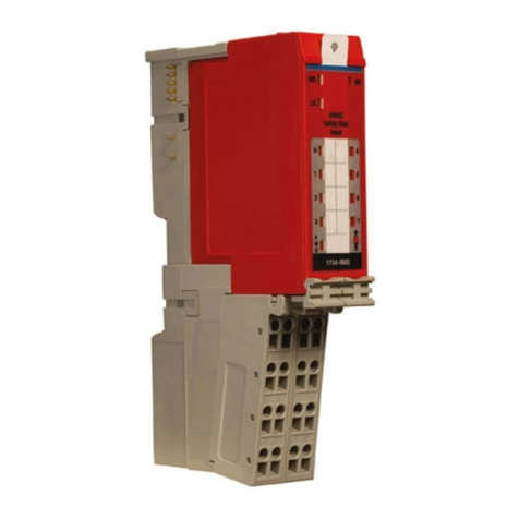
Allen-Bradley
Allen-Bradley 1734-IB8S user manual
Ross
Ross MCSE Series operating instructions
M-system
M-system R7L-EC8B instruction manual
