Skalar SA 5545 User manual

REACTOR CONTROL UNIT
SA 5545
USER MANUAL


Reactor Control Unit SA 5545
User Manual
Power supply
220-240 Volt
or
100-120 Volt
Publication no: 0101105A.US
Issue date: October 2012
Copyright Skalar Analytical B.V.
P.O Box 3237
4800 DE Breda
The Netherlands
Tel: +31 (0)76 5 486 486
Fax: +31 (0)76 5 486 400
E-mail: inf[email protected]
Internet: http://www.skalar.com

TABLE OF CONTENTS
1INTRODUCTION .....................................................................1-1
1.1 Description of the instrument...................................................1-1
1.2 Operating principle..................................................................1-2
1.3 Safety precautions ..................................................................1-3
1.4 WARRANTY REGISTRATION FORM.....................................1-5
1.5 CUSTOMER ACCEPTANCE FORM.......................................1-7
2UNPACKING AND INSTALLATION .......................................2-1
2.1 Unpacking instructions............................................................2-1
2.2 Location ..................................................................................2-1
2.3 Electrical requirements............................................................2-1
2.4 Installation instructions............................................................2-2
3OPERATION............................................................................3-1
3.1 Start-up and shutdown............................................................3-1
3.2 Adjusting the pre-set temperature ...........................................3-1
3.3 Switching off one reactor.........................................................3-2
3.4 Disconnecting one reactor.......................................................3-2
3.5 System controller ....................................................................3-2
3.6 Error messages.......................................................................3-2
4TECHNICAL INFORMATION..................................................4-1
4.1 General technical information..................................................4-1


SA 5545 Reactor control unit Chapter 1 Introduction 1-1
1 INTRODUCTION
The SA 5545 reactor control unit is an instrument with a high accuracy in
temperature control, used for temperature control of one or two reactors.
With its wide temperature range it can be used in a large field of chemical
applications with different sizes of reactors with glass or metal coils.
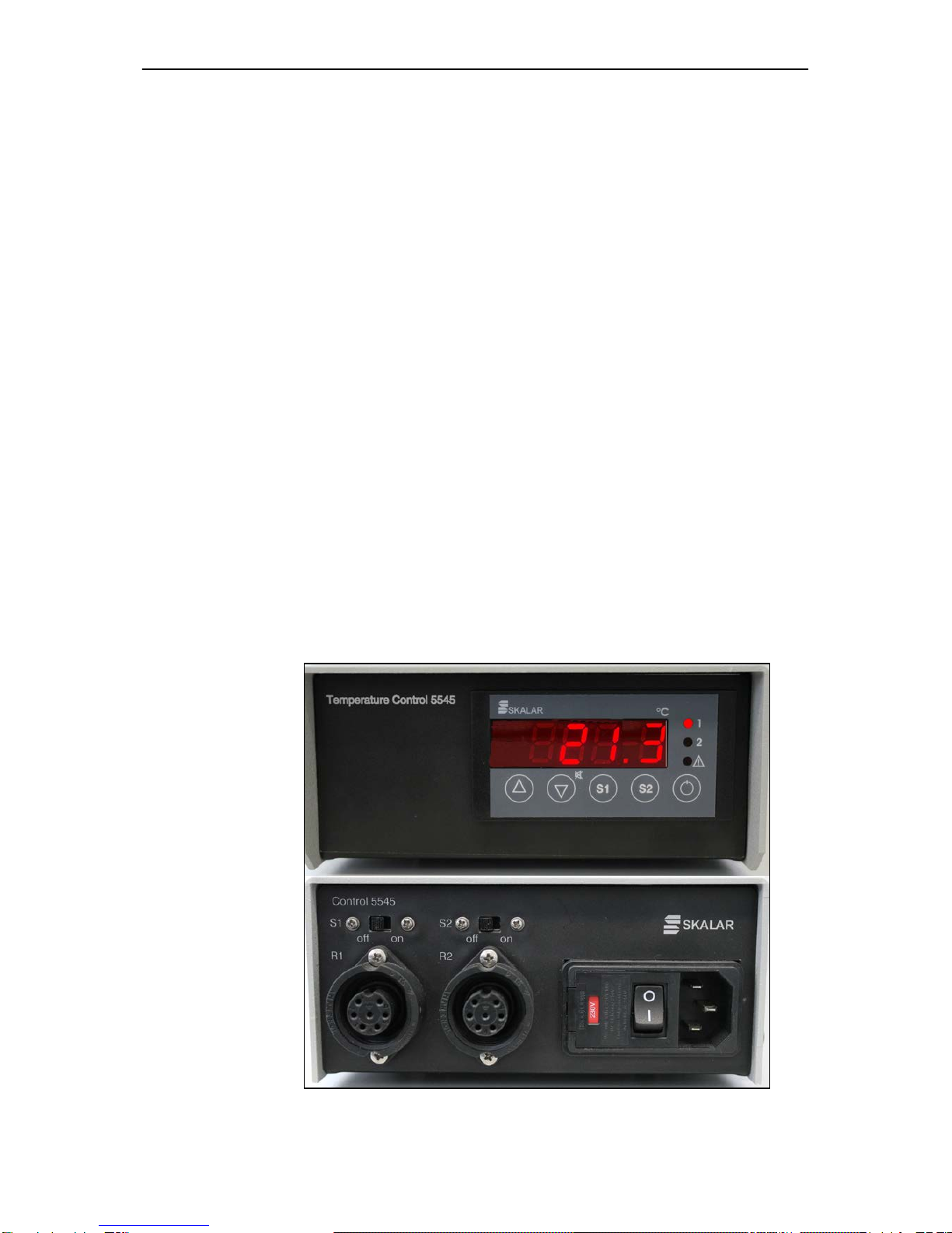
1.1 Description of the instrument
The SA 5545 reactor control unit is used to regulate the temperature of the
reactor coil. The control unit covers the power supply and the electronic
control circuit. The housing is made of stainless steel. A switchable net
entry with on/off switch and two amphenol sockets to connect up to two
reactor coils, are situated at the back of the unit. Also two dummy switches
are present for switching when only one reactor is connected. The front
panel contains the controller part with temperature display and foil buttons
for channel and temperature selection.
Figure 1.1

SA 5545 Reactor control unit Chapter 1 Introduction 1-2
1.2 Operating principle
The control unit is working according the P.I.D. principle. P.I.D. stands for:
proportional integrated differentiation principle.
The circuit operates by comparing the actual temperature in volts to a
preset value of volts. When the temperature in the reactor is almost
reaching the preset value, the heating element increases step by step the
temperature to avoid overshoot.
The actual temperature of one channel is displayed. The LED number of
the displayed channel is on. The preset temperature of a channel can be
read by keeping pressed the corresponding ‘S’ button. The preset
temperature can be adjusted by the up and down arrow buttons.

SA 5545 Reactor control unit Chapter 1 Introduction 1-3
1.3 Safety precautions
Only qualified persons should carry out all adjustments, maintenance and
repair of the instrument.
1. The instrument is designed for laboratory use.
2. Before the instrument is connected to the mains and switched on,
check whether the required voltage (indicated on the net entry at the
back of the instrument) corresponds with the line voltage.
3. The instrument power cord must only be plugged into a line supply
outlet with ground protector (earth). If an extension cord is used, make
sure that the protector line is not interrupted.
4. Opening of the instrument or disassembling parts of the instrument
while connected to the main power supply can cause severe electrical
damage along with physical injury. Before any service, repair or
change of parts, the instrument has to be disconnected from all power
supplies. Service and repair work on the voltage carrying instruments
should be avoided whenever possible. If such work is absolutely
necessary qualified personnel, who are aware of the hazards, should
carry it out.
5. Whenever it is likely that safe operation is impaired, the instrument
must be made inoperative and secured against unintended operation.
The appropriate servicing personnel must then be informed.
6. Never place the unit in an area where it will be exposed to extreme
heat, moisture or corrosive materials.
7. The instrument must be disconnected from all electrical sources when
a fuse is to be renewed.
Skalar Analytical B.V. does not accept liability for any consequences
caused by irresponsible use or irresponsible handling of the instrument, nor
for the effects and consequences induced by its use.


SA 5545 Reactor control unit Chapter 1 Introduction 1-5
1.4 WARRANTY REGISTRATION FORM
The warranty period is 12 months and starts on the date of shipment. To
activate the warranty, please return the signed warranty registration form by
the Skalar Service Desk. The warranty registration form should be received
within 2 months from the shipment date.
Warranty is ex Skalar Analytical BV and does not include traveling,
expenses and working hours at customer’s location.
Warranty is subject to the following exception(s): Glassware breakage.
Consumable products, brokerage and transport costs for the replacement
parts replaced under the warranty are to the client’s account. Skalar will not
be responsible for malfunctioning of the instrument if third party
components are used in the instrument.
All Skalar contracts are according “General terms and conditions for the
Instrument branch as issued by FHI Het Instrument”, which are available on
request.
REGISTRATION FOR WARRANTY:
Purchase order no.:
Serial no.:
Date of purchase:
Distributor:
Company name:
Address:
Post code/ZIP
City
Country:
Contact person:
Telephone number:
Fax number:
E-mail address:
Company stamp:
Name:
Signature:
The warranty registration form will only be valid when accompanied by the
signed customer acceptance form.
Please return this form to: SKALAR ANALYTICAL B.V.
PO Box 3237
4800 DE Breda
The Netherlands
Attn.: Service desk
Date:


SA 5545 Reactor control unit Chapter 1 Introduction 1-7
1.5 CUSTOMER ACCEPTANCE FORM
Company name:
Address:
Post code/ZIP code:
City:
Country:
Date:
The undersigned authorized officer confirms that the performance of the
instrument, as per the purchase order number as mentioned on the
warranty registration form, is according to the specifications as submitted
by the manufacturer.
YES
NO
Remarks:
Signature
Name


SA 5545 Reactor control unit Chapter 2 Unpacking and installation 2-1
2 UNPACKING AND INSTALLATION
2.1 Unpacking instructions
While unpacking do not discard any packing materials, till all parts have
been unpacked and checked against the packing list to insure all items are
accounted for. If any item is missing first check the packing. If it still cannot
be found, make a note of it giving as clear a description as possible using
part numbers from the manual and immediately inform the forwarder and
the supplier (see delivery conditions). Even when you think that all items
have been accounted for, check the packing.
Should there be any damaged or broken parts, repack it in the original
packing, and immediately inform the forwarder and the supplier who will
give further instructions. If the goods are supplied on trial, the original
packing material must be used for return shipment unless better is
available.
2.2 Location
The control unit should only be placed on a level, clean, dry and sturdy
surface. Place the control unit near the analyzer on the table or on a shelf
above the analyzer.
Do not locate the unit:
• In direct sunlight.
• Near an air conditioning unit.
• Near any heat or cooling source.
• Near equipment that generates intensive magnetic or electric fields.
• Near equipment that generates high frequency.
2.3 Electrical requirements
Power supply; before connecting, check the power supply is set correct for
the instrument (220-240 Volt/50 Hz or 110-120 Volt/60 Hz), see net entry at
the back of the instrument.
Note: If the power supply is not correct, open the fuse department with a
small screw driver to set the fuse holder to the required voltage and to
replace the fuses to the required voltage (2x 1.6 A for 230 V, 2x 3.15
A for 115 V). Make sure to place the fuses at the same place in
the fuse holder.
The instrument must only be connected to a line supply with ground
protector (earth). If an extension lead is used make sure the ground
protector line is not interrupted.
Max. power consumption is 320 VA, when two reactors are connected.
When one reactor is connected, the max. power consumption is 160 VA.

SA 5545 Reactor control unit Chapter 2 Unpacking and installation 2-2
2.4 Installation instructions
1. Connect the cable(s) with the (male) amphenol plug from the reactor(s)
to the (female) amphenol socket(s) at the back of the control unit.
2. When both channels are connected, the dummy switches must be set
on ‘On’. When only one channel is connected, the dummy switch for
the channel that is not connected, must be set on ‘Off’.
3. Connect one end of the power cable to the net entry of the control unit
(after checking that the voltage is correct) and the other end to the
mains.
Note: If only R2 is connected, the temperature settings must also be set
for channel 2 on the controller at the front.
Note: The internal settings of the controller are pre-set by Skalar and are
not to be changed, except when the control unit is connected to a
micro distill unit the internal settings of the temperature controller
must be adjusted for the proportional range and the cycle time to
resp. 2.0 K and 2 sec. (To be done by a Skalar Technician).

SA 5545 Reactor control unit Chapter 3 Operation 3-1
3 OPERATION
3.1 Start-up and shutdown
1. Switch on the equipment of which the controller unit is a part.
2. Switch on the control unit with the power switch on the net entry at the
back of the unit. When the controller part of the unit is switched off, the
display shows OFF.
3. Switch on the controller by pressing the Standby button during 2
seconds (most right button on the control unit). The display will show
the actual temperature of channel 1. To display the actual temperature
of channel 2: shortly press button ‘S2’.
4. Check the preset temperature for channel 1 by keeping pressed the
‘S1’ button. Do the same for channel 2.
5. If no temperature was preset or if the preset temperature is not as
required, refer to chapter 3.2 for changing or adjusting the
temperature.
6. Wait until the actual temperature is equal to the pre-set temperature.
7. The analysis can then be started.
8. When the analysis is finished and the analyzer is shutdown, switch off
the power by the switch at the rear of the unit.
3.2 Adjusting the pre-set temperature
The pre-set temperature of the reactors can be adjusted if required by
using a combination of buttons.
To increase the pre-set temperature of reactor 1:
1. Press button S1 and keep it pressed (the current pre-set temperature
is displayed).
2. Press the arrow-up button until the required pre-set temperature is
displayed. Then release both buttons. The actual temperature is
displayed again.
3. The reactor will heat up until the pre-set temperature is achieved.
To decrease the pre-set temperature of reactor 1:
1. Press button S1 and keep it pressed (the current pre-set temperature
is displayed).
2. Press the arrow-down button until the required pre-set temperature is
displayed. Then release both buttons. The actual temperature is
displayed again.
3. The reactor will cool down until the pre-set temperature is achieved.
Use the same procedure for the adjustment of reactor 2 with button S2.

SA 5545 Reactor control unit Chapter 3 Operation 3-2
3.3 Switching off one reactor
To switch off one reactor:
Press the button of the reactor to be switched off (S1 or S2) and the
Standby button at the same time during 2 seconds. The display of that
channel will show OFF.
3.4 Disconnecting one reactor
When a reactor is disconnected from the control unit, the corresponding
dummy switch at the rear must be set to ‘OFF’. If the dummy switch is not
put in the correct position the controller will give an audible signal (which
can be switched off by pressing the ‘down arrow’ button) and the display
will show ‘F1’ or ‘F2’ (depending on which channel the error occurs).
3.5 System controller
If the control unit is connected to a system controller:
The reactor can be switched on/off by means of the system controller (see
the FlowAccessTM manual). However, when one reactor was switched off
before an analysis and the system was switched off after the analysis by
the system controller, when the system is woken up the control unit starts
with both channels switched on.
3.6 Error messages
The following messages can be displayed:
F1: Caused by short circuit or crack in sensor 1. Check if the cable of
reactor 1 was properly connected to the required connector in the
separation wall between compartment 1 and 2.
F2: Caused by short circuit or crack in sensor 2. Check if the cable of
reactor 2 was properly connected to the required connector in the
separation wall between compartment 1 and 2.
EP: Lost of parameter settings. The control unit has to be sent to Skalar or
your local representative for repair.

SA 5545 Reactor control unit Chapter 4 Technical information 4-1
4 TECHNICAL INFORMATION
4.1 General technical information
Specifications
Housing: Steel sheet
Dimensions 70 x 150 x 315 mm (h x d x w)
Weight: 1.9 kg
Reactor control: Dual channel controller
Power consumption: 320 VA max.
Fuses: 1.6 A (230 V), 3.15 A (115 V)
Display 4-digits
Temperature range Adjustable from 30-160°C
Temperature stability ± 0.1°C (near sensor)
Controller type Proportional Integrating Differentiation
(PID)
Power requirements 220-240 V/ 50 Hz or 110-120 V/ 60 Hz
Temperature display LED
Table of contents


