Seneca S107USB User manual

INSTALLATION MANUAL
S107USB / K107USB
RS485/USB asynchronous serial converter
SENECA s.r.l.
Via Austria, 26 – 35127 – PADOVA – ITALY
Tel. +39.049.8705355 - 8705359 - Fax +39.049.8706287
For manuals in other languages and conguration software, visit:
www.seneca.it/products/k107usb ; www.seneca.it/products/s107usb
E
MI001076-E 1/8

MODULE LAYOUT
LED STATUS LED meaning
PWR Green ON The device is powered correctly
RX Red ON ashing It lights up every time the instrument receives data
through the RS485 port
TX Red ON ashing It lights up every time the instrument transmits data
through the RS485 port.
SIGNALS VIA LED ON FRONT PANEL
2/8
Both modules have three LEDs that allow viewing the state of the instrument activity.
S107USB LED POSITION
In the S107USB, the LEDs are positioned as follows:
S107USB LED POSITION
In the S107USB module, the LEDs are positioned as follows:
TROUBLESHOOTING
If problems occur with the use of the converter, check the following points:
PROBLEM CHECK
The “POWER” LED does not come on Check that the PC's USB socket provides for the supply
of the 5 V needed to power the instrument
The “Rx” led remains on continuously Check that the RS485 cables have not been swapped.
The received data is incorrect Check the communication speed
The S107USB and K107USB products, constitute an interface able to realize an asynchronous RS485 serial,
using a USB port present on the PC.
Thanks to the driver provided, the serial interface is treated by the operating system as a standard system serial
port, allowing the use of the product directly through any software capable of communicating with the standard
serial ports provided by the operating system (COM1, COM2, etc).
The RS485 port is also electrically isolated from the USB port, allowing eliminating many problems of electrical
noise that can occur for example when the connected equipment is very far from the PC.
PRODUCT DESCRIPTION

PRELIMINARY WARNINGS
The word WARNING preceded by the symbol indicates conditions or actions that put the user's safety at
risk. The word ATTENTION preceded by the symbol indicates conditions or actions that might damage the
instrument or the connected equipment.
The warranty shall become null and void in the event of improper use or tampering with the module or devices
supplied by the manufacturer as necessary for its correct operation, and if the instructions contained in this manu-
al are not followed.
WARNING: The full content of this manual must be read before any operation. The module must only be used by
qualied electricians.
Electrical and electronic waste disposal (applicable in the European Union and other countries with recycling). The
symbol on the product or its packaging shows the product must be surrendered to a collection centre authorized to
recycle electrical and electronic waste.
The module must be repaired and damaged parts replaced by the Manufacturer. The product is sensitive to electro-
static discharges. Take appropriate measures during any operation.
TECHNICAL SPECIFICATIONS
STANDARDS
EN61000-6-4 Electromagnetic emissions, industrial environment.
EN61000-6-2 Electromagnetic immunity, industrial environment.
EN61010-1 Safety
Note UL: use in environments with pollution degree 2 or lower. The power supply unit must
be class 2.
INSULATION
ENVIRONMENTAL
CONDITIONS
Temperature: -20 – + 65°C (-10 - +55 °C UL)
Humidity: 10%– 90% non condensing.
Altitude: up to 2000 m above sea level
Storage temperature: -40 + 85°
Protection degree: IP20.
ASSEMBLY IEC EN60715, 35mm DIN rail in vertical position.
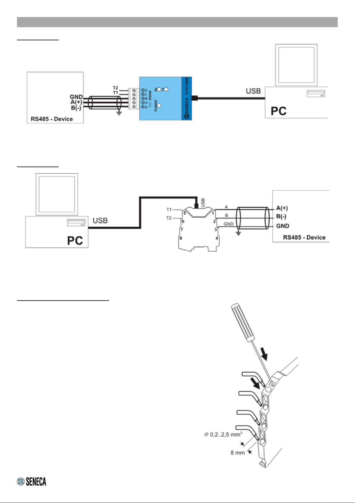
CONNECTIONS
5-way removable screw terminals, pitch 5 mm (S107USB)
Spring-loaded terminals, conductor cross-section 0.2 ... 2.5 mm2, stripping 8 mm
(K107USB)
POWER SUPPLY Through PC USB port.
SERIAL
COMMUNICATION
RS485 through MODBUS -RTU protocol, 32 nodes maximum.
Possibility of multiple connection of several S107USB or K107USB units on the same PC.
BAUDRATE 1200 bps,115200 bps.
3/8
WARNING
the maximum working voltage between any
terminal and ground must be less than 50
Vac / 75Vdc
Power
Supply
Input
Output
1500 V~
RS485 USB
In/Out

INSTALLATION REGULATIONS
The module has been designed for vertical installation on a DIN 46277 rail. Avoid mounting modules over heat-gen-
erating equipment. Installation in the bottom part of the electrical panel is recommended.
Insertion in the DIN rail
As shown in gure:
1. Hook the module in the upper part of the rail.
2. Press the module down.
4/8
With regard to the S107USB instrument, there are no particular precautions to follow, except that of using a shielded
cable for the RS485 lines for long connections or connections in noisy environments (please refer to the Electrical
Connections section).
S107USB INSTALLATION REGULATIONS
K107USB INSTALLATION REGULATIONS
For long connections or in noisy environments, use a shielded cable for the RS485 line (refer to the Electrical Con-
nections section)
Removal from the rail DIN
As shown in gure:
1. Lever with a screwdriver (as shown)
2. Rotate the module upwards.

5/8
ELECTRICAL CONNECTIONS
S107USB: the electrical connections of the S107USB are shown below:
By inserting an external jumper between terminals T1 and T2, the terminator of the RS485 line is enabled.
We also recommend to use a shielded cable for the RS485 line, in particular if long connections are to be made or
in noisy environments.
K107USB: the electrical connections of the S107USB are shown below:
By inserting an external jumper between terminals T1 and T2, the terminator of the RS485 line is enabled.
We also recommend to use a shielded cable for the RS485 line, in particular if long connections are to be made or
in noisy environments.
Terminal connections:
The module has spring-loaded terminals as electrical con-
nections.
To make the connections refer to the following instructions:
1 - Strip the cables by 0.8mm
2 - Insert a at-blade screwdriver into the square hole and
press it until the locking spring of the cable
opens.
3 - Insert the cable into the round hole
4 - Remove the screwdriver and check that the cable is
rmly xed in the terminal

6/8
DRIVER INSTALLATION
The user is provided with a CD containing the instrument driver.
In this section we will describe in detail the driver installation procedure.
It should be noted that the installation in Linux environments (with Kernel 3.0.0-19 or later) is automatic and does
not require the driver CD. The standard serial port of the PC with which the device is identied is the following:
/dev/ttyUSB0.
As for Windows operating systems, it is important to stress that the procedure consists of two distinct phases,
equally important for the nal use of the instrument. In the rst part the driver of the actual serial converter will be
installed. Through the second phase the virtual driver will be installed which will allow the use of the peripheral as
a standard serial port of the operating system.
If you are using Windows 7, these two phases are identical and are followed step by step, while for other versions
of Windows the second part is automatically managed by the operating system without further dialogue with the
user. Below is the installation procedure for Windows 7.
DRIVER INSTALLATION WITH WINDOWS 7:
Connect the instrument to the PC already switched on, so that the operating system can detect the presence of
the device automatically. As soon as the operating system detects the presence of the converter, the installation
will begin and the following messages will be displayed:
FIG. 1
FIG. 2

7/8
If the installation does not start automatically, you will have to proceed manually, following the instructions given.
First of all you need to have an internet connection allowing the instrument to perform the driver update following
the automatic procedure or by connecting (http://www.ftdichip.com/Drivers/VCP.htm). For the automatic proce-
dure, congure as in Fig 3.
On the next screen proceed as follows:
At the end of the search for the driver, a screen appears that shows the update and installation have been carried
out correctly. It will therefore be possible to see the instrument among the installed USB devices and among the
serial communication ports. (COM1, COM6 etc..)
FIG. 3
FIG. 4
FIG. 5

8/8
CONTACT INFORMATION
This document is the property of SENECA srl. Copies and reproduction are prohibited unless authorised. The con-
tent of this document corresponds to the described products and technologies.
Stated data may be modied or supplemented for technical and/or sales purposes.
ACCESSORIES
CODE DESCRIPTION
CU-A-MINIB-2 USBA-miniB 2-metre communication cable
K-BUS Expandable 2-place connector, EN 60175 (only for K107USB)
This manual suits for next models
1
Table of contents