Senergy SEN803FCT-RC/2 User manual
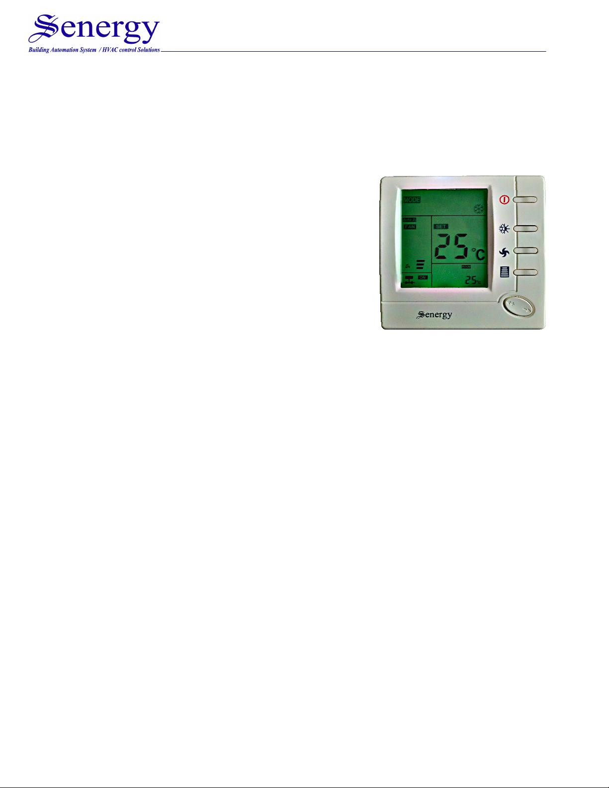
SEN803FCT-RC/2 FAN COIL THERMOSTAT
Applications : Control FCU with Cooling/Heating Mode, 03-Fan Speed
INTRODUCTIONS-----------------------------------------------------------------------------------------
The 803FCT/2 Series of Digital thermostats are
specifically designed for control of commercial
heating and cooling equipment such as rooftop
units (with and without economizers), heat pumps,
and fan coil unit. The large LCD display is easy to
set up and program through the use of a plain text
menu driven backlit display that walks the user
through the programming process. Additionally, the
803FCT/2 has over four configurable parameters,
enabling the thermostats to adapt to a variety of
applications..
SPECIFICATION-------------------------------------------------------------------------------------------
Power Supply…………………………...….....100~240VAC,50/60Hz
Fan speed Relay………………………….......2A
Cooling/Heating Relay…………………….....0.5A
Room Temperature Scale…………………...5
o
C to 35
o
C
Dimensions…………………………….…...…86x86x15mm( 3.38x3.38x0.6inch)
FEATURES AND BENEFITS---------------------------------------------------------------------------
−Large LCD display with backlight
−Temperature adjustments are simple with the large up-down arrows
−Display shows both set points and room temperature simultaneously
−Maintains the temperature to within 1 degree set point
−Auto fan with adjustable 3-fan speed
−Permanent user setting retention during power loss, no batteries are required
−Input room card for energy saving mode Room Card Function
FRONT VIEW------------------------------------------------------------------------------------------------
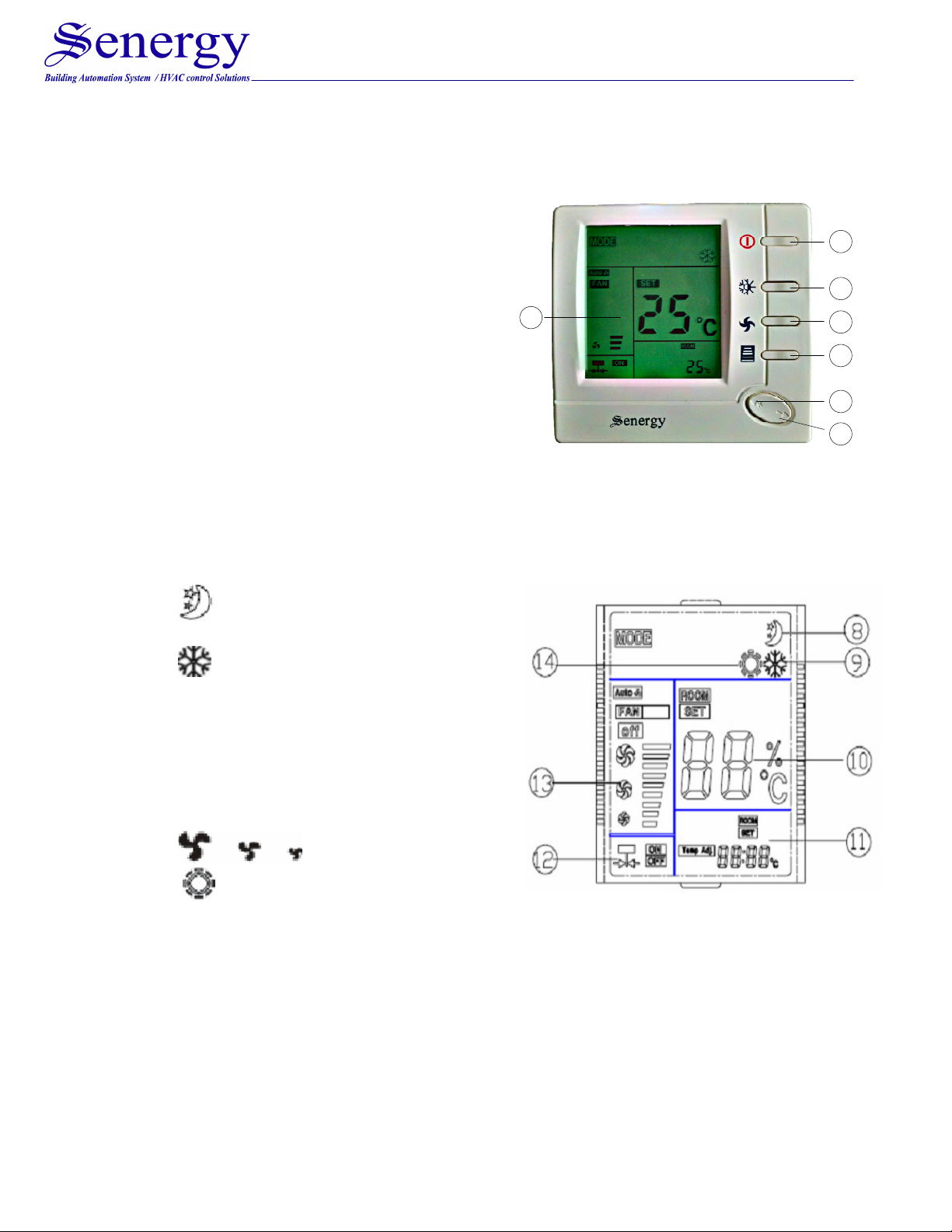
The Thermostat Buttons and Switches
(1) Display area
(2) Power button
(3) System button (COOL, HEAT)
(4) Fan speed option button
(HI MED LOW AUTO)
(5) Sleep operation button
(6) Raises temperature setting
(7) Lowers temperature setting.
1
2
3
4
5
6
7
Display area:
(8) Show when thermostat is in sleep
mode operation
(9) Show thermostat is in Cooling
mode operation
(10) Show room temperature or
setpoint temperature
(11) Show setpoint temperature or
room temperature
(12) Indicate the output to motorized
valve is ON or OFF
(13) Show fan speed option
(14) Show thermostat is in Heating
mode operation

INSTALL THE THERMOSTAT: -----------------------------------------------------------------------
WARNING : ELECTRICAL SHOCK HARZARD
•Turn off power at the main service panel by removing the fues or switch
the appropriate circuit breaker to the OFF position before removing the
existing thermostat.
IMPORTANT :
•Thermostat installation must conform to local and nationl building
electrical codes and ordinances.
1. Remove the packing material from the thermostat. Gently pull the control
panel straight off the base. Forcing or prying on the thermostat will cause
damage to the unit.
2. Connect wires beneath terminal screws on power supply module using
appropriate wiring schematic.
3. Push power base into 86mmX86mm conduit box.
4. Using two mounting screws mount the power base to the wall. Place a level
against bottom of base, adjust until level, and then tighten screws. (Leveling
is for appearance only and will not affect thermostat operation.)
5. Replace control panel on the power base by snapping it in place.

WIRING DIAGRAM----------------------------------------------------------------------------------------
CHECK THERMOSTAT OPERATION:--------------------------------------------------------------
Fan operation
1. Press fan button, display will show and Auto separately means
fan rotate in HI MED LOW or AUTO speed.
2. If you select AUTO speed, fan operation will change speed according to the
difference between the room temperature and set temperature.
a. If room temperature is 3℃higher than setting temperature in cooling or
3℃lower than setting temperature in Heating. Fan will run in HI speed.
b. If room temperature is 2℃- 3℃higher than setting temperature in
cooling or 2℃-3℃lower than setting temperature in Heating. Fan will
run in Medium speed.
c. If room temperature is 0℃-2℃higher than setting temperature in cooling
or 0℃-2℃lower than setting temperature in Heating. Fan will run in Low
speed.
Heating system operation
1. Press system switch to heat mode
2. Press “+” to adjust the thermostat setting above the room temperature. The
heating system should start to operate.
3. Press “-“ to adjust the thermostat setting below the room temperature. The
heating system should stop operating.

Cooling system operation
1. Press system switch to cool mode
2. Press “-“ to adjust thermostat setting below room temperature. The cooling
system should start to operate.
3. Press “+” to adjust temperature setting above room temperature. The cooling
system should stop operating.
Sleep mode operation
Push sleep operation button ⑤, appears indicate during the following 8 hours,
the thermostat will control heating or cooling according to following curve. Push sleep
operation button again, disappears indicate the sleep operation feature is canceled.
•System switch on cooling mode: To achieve better sleep, 1 hour after
sleeping mode setting, set point temperature will raise 1℃automatically, and 2
hours later, setting point temperature will raise 2℃and keep on with this
temperature until timer off, which is 8 hours. After timer off, set point will be
restored to formal setting automatically.
•System switch on heating mode: To achieve better sleep, 0.5 hour after
sleeping mode setting, set point temperature will decrease 1℃automatically,
and1 hour later, setting point temperature will decrease 2 ℃, 2 hours later,
setting will decrease 3℃and keep on with this temperature until timer off,
which is 8 hours. After timer off, set point will be restored to formal setting
automatically.
Room card function operation (Energy Saving Mode)
1. The temperature will keep in auto mode and temperature can not be adjust
when the room card removed (auto mode, the temperature will keep setting
of 25℃in cooling mode; and 18℃in heating mode. See programming and
configuration )
2. The temperature could be adjust when plug in the room card , others function
would be available .(terminal 7and 8 will connect).
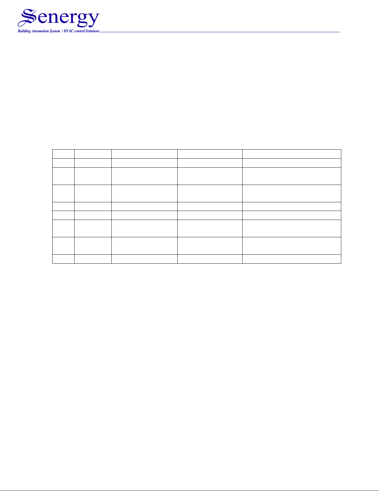
PROGRAMMING AND CONFIGURATION---------------------------------------------------------
The configuration menu allows you to set certain thermostat operating
characteristics to your system or personal requirements. Switch off the thermostat and
hold the sleep operation Button ⑤for over 4 second till power on again means you
have entered the first configuration menu item. There are 7 menu items. Press button
⑤to change to the next item. To exit the menu and return to the normal operation,
switch off the thermostat and switch it on again. If no keys are pressed within 20
seconds the thermostat will be switched off.
Item
Button Display(default) Press +,-
to select
Description
1 (4) 3 sec 01 (0) -3 … 3 Temperature adjustment
2 (4) 02 (35
o
C) 26
o
C … 35
o
C Set Maximum Temperature
Limitation
3 (4) 03 (5
o
C) 5
o
C … 24
o
C Set Minimum Temperature
Limitation
4 (4) 04 (On) OFF/ON Select Fan Mode
5 (4) 05 (SC) SC/0C/00 Active Room Card Mode
6 (4) 06 (25
o
C) 25
o
C … 30
o
C Energy Saving Setpoint in
Cooling Mode
7 (4) 07 (18
o
C) 10
o
C … 18
o
C Energy Saving Setpoint in
Heating Mode
8 (4) 08 (COOL) COOL/ALL/HEAT
Select Mode
Item 1: The display will show “Temp adjust” and its default setting value is 0 in the
configuration menu. Selecting between “–3” to “+3”. You can adjust the room
temperature display up to 3 deg. lower or higher.
Item 2: The display will show 37℃which is the default factory maximum temperature
limitation. Using “+” & “-” button to set the maximum limitation. It can be change
between 26℃to 37℃.
Item 3: The display will show 5℃, which is the default factory minimum temperature
limitation, Using “+” & “-” button to set the minimum temperature limitation. It can be
change between 5℃to 24℃.
Item 4: The display will show “On”which is the factory default setting for fan option.
Using “+” & “-” button to select between “On” and “OFF”. If you select “On”, the
thermostat will turn on the fan at a speed provided by the Fan Switch and will not stop
the fan when there is no call for heat or cool. If you select “OFF”, the thermostat will
stop the fan when there is no call for heat or cool.

Item 5: The display will show “SC”which is the factory default setting for room card
input option. Using “+” & “-” button to select between “SC”, “OC” or “00”. If you select
“SC”, the thermostat will be operated in energy saving mode when the room card input
dry contact is closed. If you select “OC”, the thermostat will be operated in energy
saving mode when the room card input dry contact is open. If you select “00”, the
energy saving mode will be disabled.
Item 6: The display will show 25℃which is the factory default setting for energy saving
temperature setpoint in cooling mode. Using “+” & “-” button to select between 25℃to
30℃.
Item 7: The display will show 18℃which is the factory default setting for energy saving
temperature setpoint in Heating mode. Using “+” & “-” button to select between 10℃to
18℃.
Item 8: The display will show Cooling Mode which is the factory default setting. There
are three modes : Heat/Cool/All
Table of contents


