SenseAir aSENSE VAV User manual

EM aSENSE-VAV (Modbus) all housings installation Oct'08
1 of 11
Installation Manual for All Housings
a
aa
aSENSE
SENSESENSE
SENSE™ VAV
VAV VAV
VAV
CO
2
/ temperature sensor with built-in
general purpose controller for wall mounting
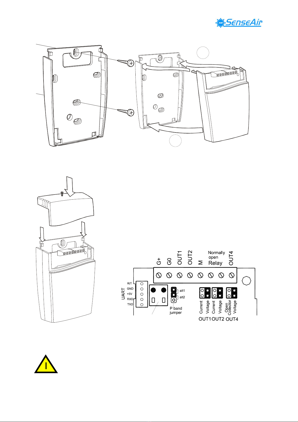
Dismounting of the sensor
4
3
2
6
1
5
Pull the top part upwards
1
Push the front part with the lid upwards Fold the front part with the lid forwards
while keeping the wall plate steady and loose it from the hooks (#1)
1 top part
2 lid
3 front part
4 wall plate
5 screw
6 label with settings
inside the top part
EM aSENSE-VAV (Modbus) all housings installation Oct'08
2 of 11
Mounting of the sensor
A
B
The wall plate is screwed onto the wall A Put the top tabs of the front part into the top holes of
The screw heads should be max 4 mm the wall plate.
B Press the lower edge of the case onto the wall plate to
latch
DI1
The top part is pushed under the Terminals and jumpers on
aSENSE™
VAV
standard
.
locking hooks of the wall plate The darker positions are default settings.
and is secured with a screw Terminals and jumpers are located under the top part.
If for some reason the PCB must be removed it must be handed carefully and
protected from electrostatic discharge! Normally, removing the PCB is not
required.

EM aSENSE-VAV (Modbus) all housings installation Oct'08
3 of 11
Dimensions and holes
120(4,72)
31(1,22)
83(3,26)
Dimensions of sensor in mm and (inches)
29,8(1,17)
30(1,18)
7,8(0,31)
4,2(0,16)
2(0,08)
52,5(2,07)
30(1,18)
25(0,98)
30(1,18)
Dimensions of mounting plate in mm and (inches)
EM aSENSE-VAV (Modbus) all housings installation Oct'08
4 of 11
aSENSE
aSENSEaSENSE
aSENSE™ VAV
VAVVAV
VAV
CO
2
/ temperature sensor with built-in
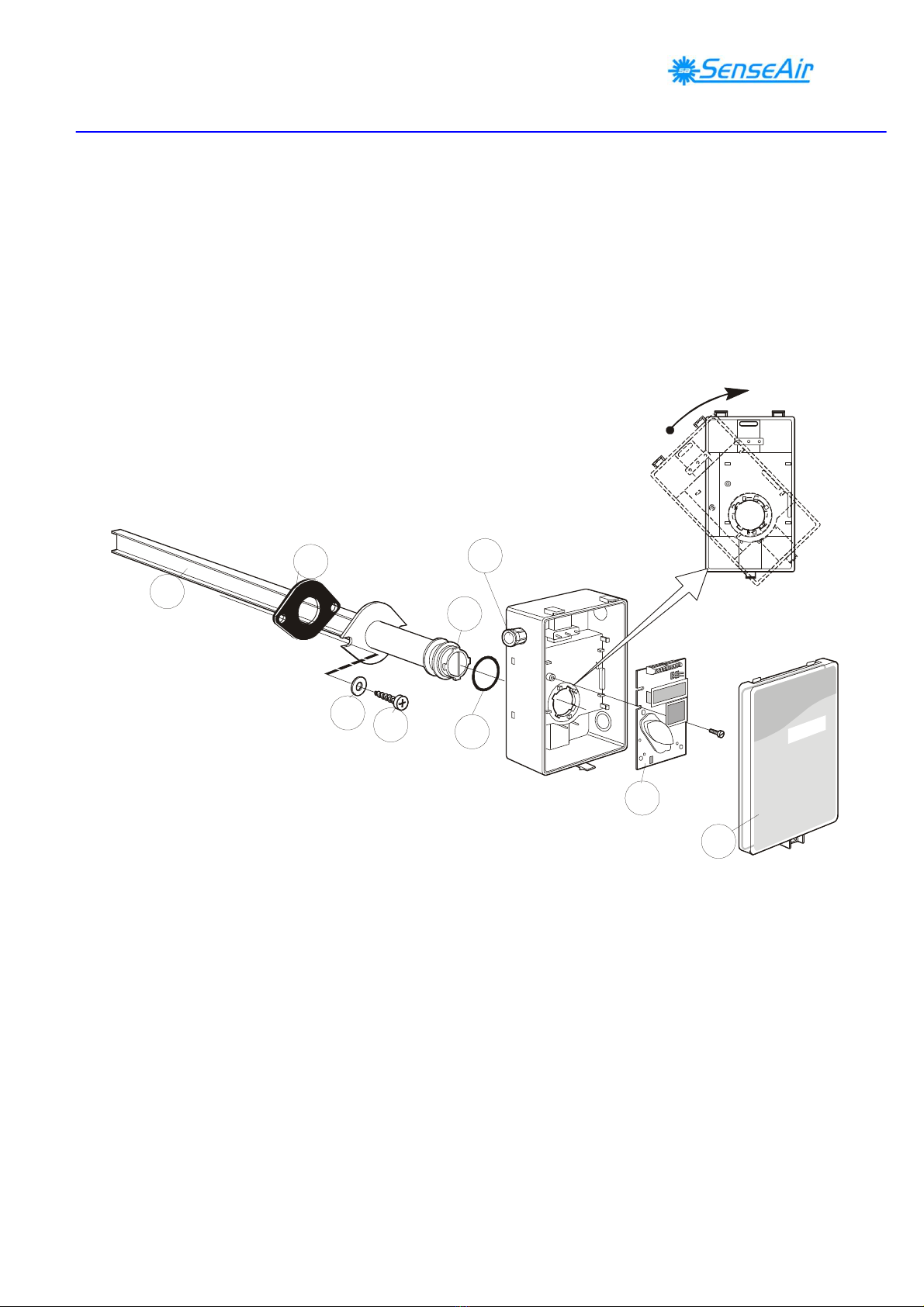
general purpose controller for mounting in
ventilation ducts
1
2
1
2
3
4
5
6
7
9
8
1 Sampling probe 6 O-ring 29,2x3,53 (Factory supplied mounted in box)
2 Sealing gasket 7 PCB (Factory supplied mounted in box)
3 Largest locking nob 8 Snap-in lid
4 2 washers BRB 5,3x10x1 9 PG9 cable entry bushing
5 2 screws RXS 4,8x16
EM aSENSE-VAV (Modbus) all housings installation Oct'08
5 of 11
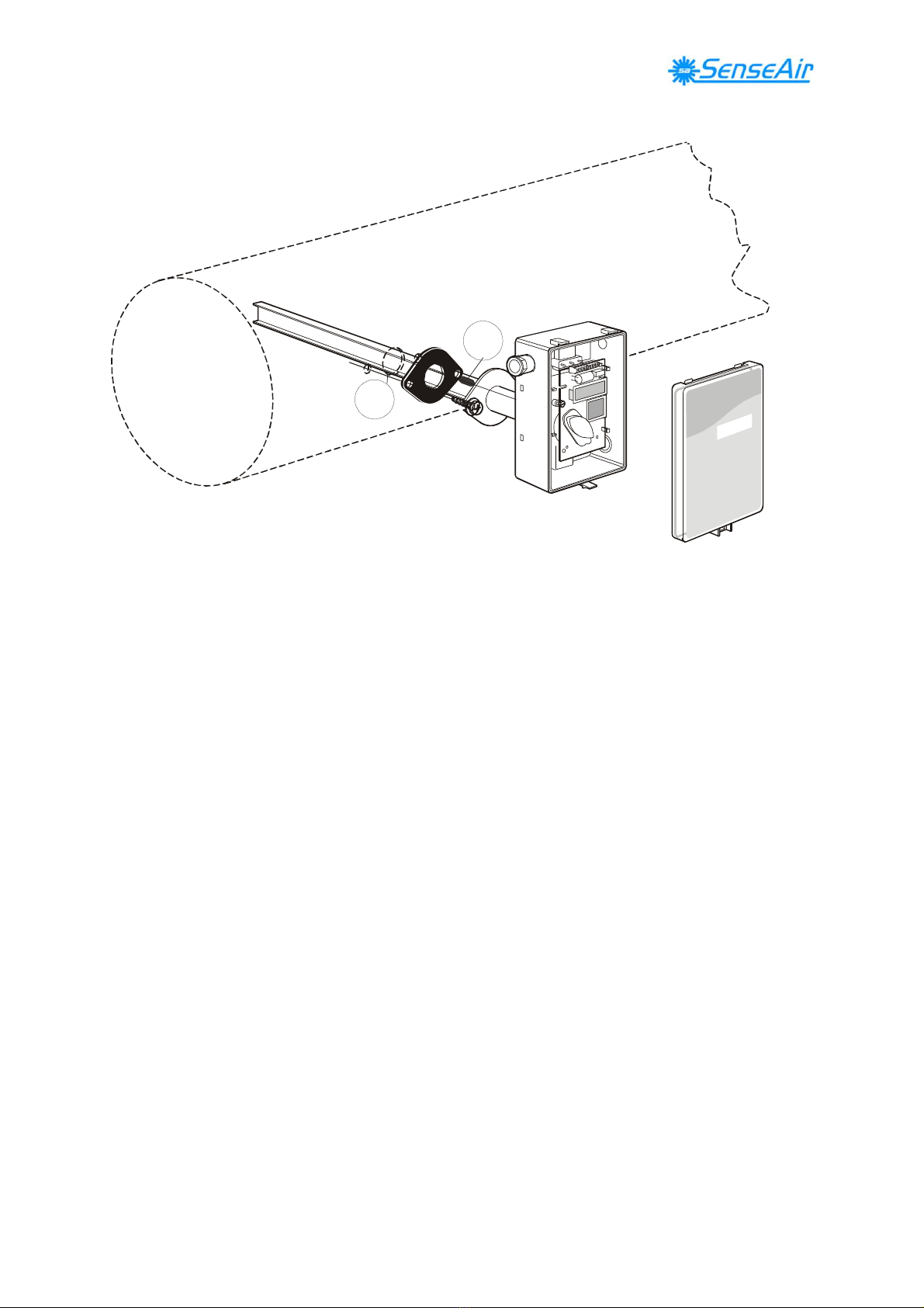
Mounting of
aSENSE
aSENSEaSENSE
aSENSE™ VAV
VAVVAV
VAV
on to the duct.
11
10
10 Hole with 25 mm diameter
11 Temperature sensor with 110 mm cable mounted in the sampling probe
Mounting Instruction
Since there might be a substantial pressure difference in duct mounting applications, it is
essential to avoid ambient air from suction into the duct-mounting box. For correct function it
is indispensable that the sealing of the box cover, the cable entry bushings, the cable feed
through and the duct entrance are absolutely tight. The duct entrance may need extra sealing
paste in order to prevent leakage. The PCB must be handed carefully and protected from
electrostatic discharge.
1) Electrical cable entry: The box has a factory mounted cable entry bushing in dimension
PG9. Never feed more than one cable through each cable entry bushing, or else gas might
leak through!
2) Mounting the tube: Drill a hole (10) with 25 mm diameter (or 1 inch) for the sampling
probe and two holes with 4 mm diameter for the screws (5) into the air duct and mount
the tube (1) with the gasket (2). The sampling probe should be mounted with the largest
locking knob on top. The unit can be mounted with the air coming from the left or right.
3) Attaching the sensor box is made to the sampling probe by a snap-in bayonet fitting.
First, carefully stick the temperature probe (11) into the sampling probe. (1). Orient the
box onto the sampling probe so that the box upside is on the same side as the largest
locking knob (3). When the probe is fitted into the notches of the box, then turn the box
clockwise until stop (see Figure 1). Position 1 indicates open where the box can be
removed from the sampling probe. In position 2 the box is locked to the probe
.

EM aSENSE-VAV (Modbus) all housings installation Oct'08
6 of 11
DI1
Terminals and jumpers on
aSENSE™
VAV
standard
.
The darker positions are default settings.
Dimensions
85(3,35) 10(0,39)35(0,38)
40,3(1,59)
203,4(8,01)
9,5(0,37)
141,8 (5,58)
40(1,57)
85 (3,35)
2,7(0,04)
24(0,94)
22 (0,87)
Dimensions of sensor in mm and (inches)
66 (2,6)
55 (2,16)
56 (2,2)
6 (0,24)
Dimensions of sampling probe in mm and (inches)
EM aSENSE-VAV (Modbus) all housings installation Oct'08
7 of 11
a
aa
aSENSE
SENSESENSE
SENSE™ VAV
VAV VAV
VAV
CO
2
/ temperature sensor with built-in
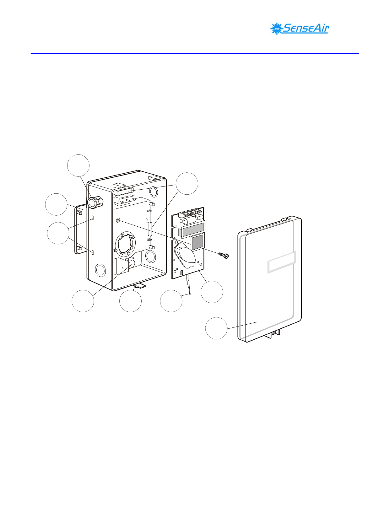
general purpose controller mounted in industrial
housing
5
78
8 6 3
4
2
1
1 Wall plate 5 Snap-in lid
2 PCB (Factory supplied mounted in box) 6 Locking screw of the lid (not shown)
3 Temperature sensor 7 PG9 cable entry bushing
4 Hole for wall plate hooks 8 Air holes
EM aSENSE-VAV (Modbus) all housings installation Oct'08
8 of 11
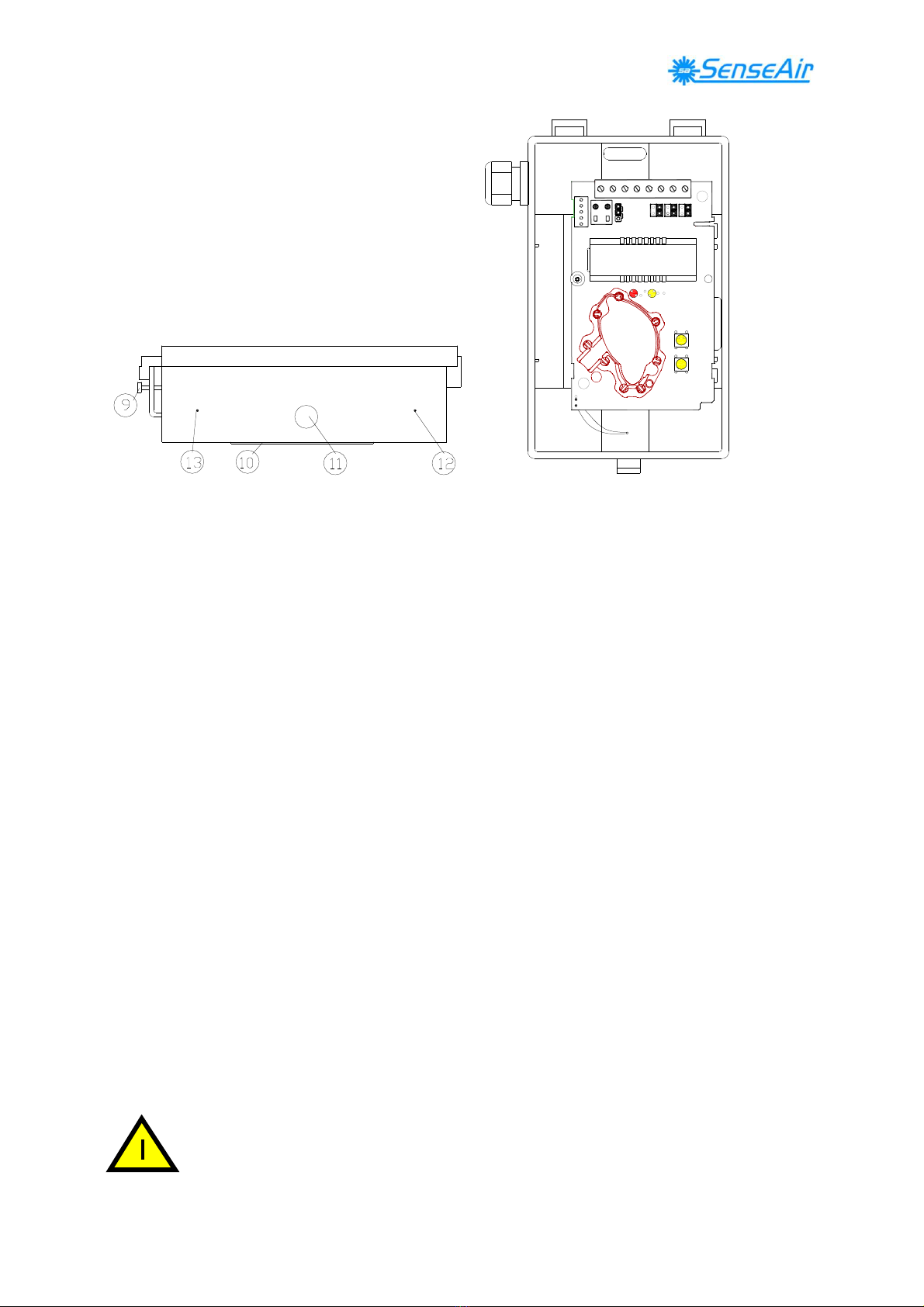
9 Lid locking screw
10 Wall plate
11 Screw to hold the wall plate
12 Drill mark for cable entry bushing
13 Drill mark for cable entry bushing
Dismounting the wall plate
The sensor is delivered with the wall plate mounted. The wall plate has to be removed before
the sensor is mounted onto the wall. Unscrew the screw on the side of the box. See figure 3.
Wall Mounting Instruction
Normally the PCB should not be removed from the housing. If for some reason the PCB must
be removed it must be handed carefully and protected from electrostatic discharge.
1) Electrical cable entry: The box has a factory mounted cable entry bushing in
dimension PG9. Never feed more than one cable through each cable entry bushing, or
else gas might leak through!
2) Screw the wall plate onto the wall: The wall plate has holes for three screws. Drill
holes for 3,5mm screws and put dowel into them. Dowels and screws 3,5 x 25mm are
included in a plastic bag
3) Attaching the sensor box to the wall plate is done by a snap-in fitting. The wall plate
has three hooks that fit in holes in the sensor box. Fasten the screw on the side of the
box.
4) The lid can be locked with the screw at the bottom of the sensor box.
If for some reason the PCB must be removed it must be handed carefully and
protected from electrostatic discharge! Normally, removing the PCB is not
required.

EM aSENSE-VAV (Modbus) all housings installation Oct'08
9 of 11
DI1
Terminals and jumpers on
aSENSE™
VAV
standard
.
The darker positions are default settings.
85 (3,35)
9,5 (0,37) 141,8 (5,58)
40 (1,57)
85 (3,35)
10(0,39)
38,5(1,5)
Dimensions of sensor in mm and (inches)
82(3,23)
66(2,60)
41(1,61)
17,5(0,69)
40,5(1,59)
63(2,48)
Ø5(0,20)
Ø5(0,20)
Ø5(0,20)
42(1,65)
39,9(1,57)
Dimensions of wall plate in mm and (inches)
EM aSENSE-VAV (Modbus) all housings installation Oct'08
10 of 11
Electrical connections
The power supply has to be connected to G+ and G0. G0 is considered as system ground. The
same ground reference has to be used for the
aSENSE™
VAV
unit and for any connected
device! Unless different transformers are used, special precautions need to be taken.
PLEASE NOTE!
The signal ground is not galvanically separated from
the
aSENSE™
VAV
power supply!
NOTE!
The same ground reference has to be used for
the
aSENSE™ VAV
unit and for any
connected device!
If possible keep the sensor powered up after mounting.
Connect the analogue output before measuring.
Connection
Terminal
Function
Electrical Data
Remarks
G+
G0
Power (+)
Power ground (-)
24 VAC/DC+ (+-20%), 3W
24 VAC/DC-
2W without output load
See note 1!
OUT 1
OUT 2
M
Analogue Output 1 (+)
Analogue Output 2 (+)
Signal Ground (-)
0-10 VDC or 0-20 mA,
2-10 VDC or 4-20 mA,
Same as Output 1
Connected to G0 via PTC fuse
According to positions of
OUT1 jumper and start point
selection. See note 2!
According to positions of
OUT2 jumper and start point
selection. See note 2!
See note 1!
Relay
Relay
Normally open
Contact free relay
minimum load 1mA/5V
rated load 0,5A/125VAC;
1A/24VDC
Triggered by register OUT3
OUT4
Analogue Output 4 (+)
or Open Collector
0-10 VDC
Max 0,5A, 55VDC / 40VAC
(half-wave rectifier protection)
According to positions of
OUT4.
See note 2 & 3!
DI1
DI1
Digital Input 1
Closed contact current 1mA
Open contact voltage max 5V
Do not apply any voltage
on this input!
Table I. Electrical terminal connections for
aSENSE™
VAV
Note 1
:
The ground terminal is used as negative power supply DC input or AC phase ground G0
(halfwave rectifier). The signal ground M, protected by a PTC resistor, is the same as power ground
G0 (permitting a ”3-wire” configuration). A single transformer may be used for the entire system.

EM aSENSE-VAV (Modbus) all housings installation Oct'08
11 of 11
Note 2:
aSENSE™
VAV
can deliver both a voltage or a current loop for OUT1/OUT2. For OUT4 a
voltage output or an open collector output is selected with jumper OUT4. To change between voltage
and current output mode the hardware jumpers are used. There is one jumper for OUT1 and one for
OUT2, so that one output can be a voltage output and the other a current output. Both, voltage output
and current output, can have start points 0 % (0-10 VDC or 0-20mA) or 20% (2-10 VDC or 4-20mA)
selected from PC software.
Note 3:Current of Open Collector is internally returned to G0 terminal.
DI1
Terminals and jumpers on
aSENSE™
VAV
standard
.
DI1
Terminals and jumpers on
aSENSE™
VAV
with communication jumper
Other manuals for aSENSE VAV
1
Table of contents
Other SenseAir Accessories manuals


