Sensit SHV1 User manual
SENSIT s.r.o.
Školní 2610, 756 61 Rožnov pod Radhoštěm, Company ID 64087484, VAT ID CZ64087484, Tel.: +420 571 625 571, Fax: +420 571 625 572
The company is registered in the Commercial Register administered by the Regional Court in Ostrava, Section C, Entry 13728, se[email protected]z, www.sensit.cz
5302.1
10.16
Replaces
INSTRUCTION MANUAL
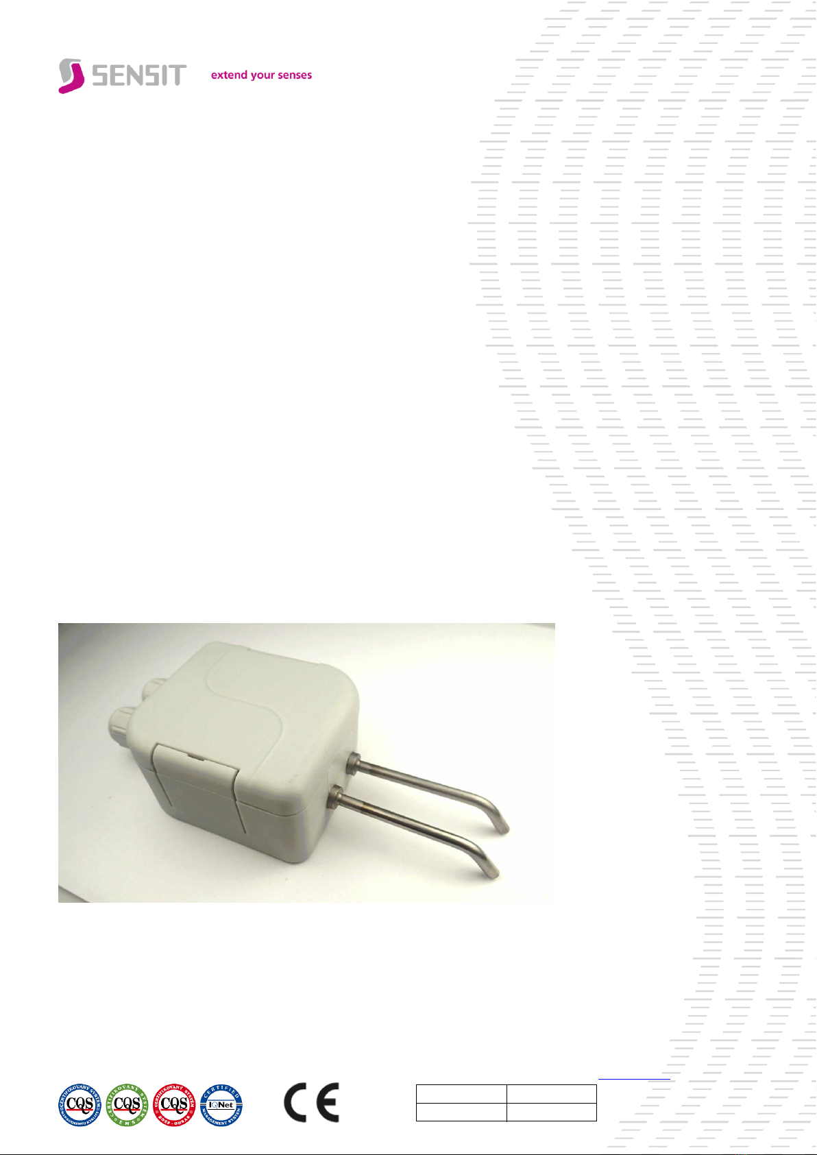
FLOOD SENSOR SHV1 –OUTR
The flood sensor is made as a two-state controller designed for monitoring
and indicating fault conditions related to water leakages.

Legal regulations and standards:
•Electrical connection of the sensor may only be carried out by a competent person with electrician qualification who is
familiarized with the "Instruction Manual" in detail.
•The Instruction Manual is part of the product and it is necessary to keep it for the entire service life of the product.
•The Instruction Manual must be transferred to any other owner or user of the product.
•The disposal must be performed in compliance with the Directive 2008/98/EC of the European Parliament and of the
Council - on waste and the Directive 2012/19/EU of the European Parliament and of the Council –on waste electrical
and electronic equipment (WEEE), as amended
•The sensors are delivered in packages, which guarantee resistance to mechanical influences and that meet the
conditions with the European Parliament and Council Directive 94/62/ES on packaging and packaging waste.
•The final metrological inspection –comparison with standards or working instruments –is carried out for all the
products. Continuity of the standards and working measuring instruments is ensured within the meaning of the
Section 5 of Act no.505/1990 on metrology. The manufacturer offers a possibility to supply the sensors calibrated in
SENSIT s.r.o. laboratory (according to EN ISO/IEC 17025 standard) or in an Accredited laboratory.
Sensor use:
The flood sensors SHV1 are designed for indicating fault conditions (e.g. water leakage) in operations of heat exchange
stations and boiler rooms, in production floors, residential houses and offices. Sensors act on the conductivity principle
and are capable of detecting fluids with a conductivity higher than 2 mS/m, which enables their use for standard
applications with surface water with a conductivity of 5 mS/m and higher. The maximum temperature around the sensor
head is 80 °C and must not be exceeded even for a brief period. The sensors meet ingress protection IP 65 according to
CSN EN 60 529.
Possible applications of the flood sensors:
•Pump shutdown upon reaching a required level
•Flooding of buildings by groundwater, floods, sewage
•Flooding of sumps, pump activation upon reaching a certain level
•Water leak indication for washing machines, boilers, pump units, etc.
•Room flooding due to a failed equipment –broken toilet water supply line, overflowed bathtub, sink
•Monitoring of condensate in a ventilation duct
Basic operating positions of the sensor:
•Horizontal –sensing electrodes are level with the bottom of the box, which ensures that the floor flooding is
monitored from the start.
•Vertical (perpendicular on a wall) –the sensor can be installed at a required height above the monitored surface. For
this application, the sensor can be attached to wood (or similar) surfaces using wood screws and to a masonry
surfaces using corresponding plugs and screws.
Warnings and restrictions:
The sensor must not be used for measuring in locations
•Where the specified technical parameters and operating conditions are not adhered
•Where the sensor is exposed to mechanical action or in areas with explosion hazard
•With chemically aggressive environment that does not correspond the used metal materials
•Where the plastic head of the sensor is exposed to prolonged immersion in liquid or intense jetting liquid
The sensor should not be used in areas:
•Where the water contamination level is high and the alarm could be enabled also after the level drop due to the
conductive coating between the electrodes –in that event it is necessary to clean the surface of the box with a
suitable cleaning agent.
•Where the water conductivity is lower than 1.5 mS/m –the sensor sensitivity is not set for the use of distilled and
demineralized water (usually 0.05 to 0.3 mS/m).
•Where the switch might be exposed to effects of strong organic and inorganic acids with medium and strong
concentrations at high temperatures, weak organic acids with high concentrations and high temperatures, chlorinated
hydrocarbons, and undiluted alkaline substances
•Where the supply cable might run parallel to mains cables (risk of interference signal induction and the measurement
results may be influenced), the safe distance from mains power cables when cables run parallel can be as much as
0,5 m according to the nature of interfering fields
Failure to follow the said recommendations will negatively affect measurement accuracy, reliability and service life of the
temperature switch.
Recommendations:
In application with the requirement for switching higher output loads (devices), we recommend the use of a
flood sensor in combination with a power component (contactor, SSR relay, etc.).

Product safety:
Product safety and technical parameters were evaluated according to the following standards and norms, as amended:
•EN 61003-1, EN 60 529
•EN 61326-1, EN 55011
Declaration of conformity:
SENSIT s.r.o. provides the product with the EU Declaration of Conformity issued according to Act No. 90/2016 Coll.
and Act No. 22/1997 Coll., as subsequently amended. The product is in accordance with the following directives:
•European Parliament and Council Directive 2011/65/EU of 8 June 2011 on the restriction of the use of certain
hazardous substances in electrical and electronic equipment
•European Parliament and Council Directive 2014/30/EU of 26 February 2014 on the harmonisation of the laws of the
Member States relating to electromagnetic compatibility
Description of the sensor:
The sensor consists of metal sensing electrodes and a plastic head containing evaluation electronics. Both the supply
voltage connection and the idle condition of the transistor output are indicated by a green LED. The failure condition –
a conductive connection made between the electrodes –is indicated by a red LED inside the box and by a change
of condition of output relay contacts. Output relay contacts are selected by positioning a jumper on DPS as described in
the part “Wiring diagram”. All metal parts are made of class DIN 1.4301 stainless steel; the basic length of the sensing
electrodes is 50 mm. The supply cables are connected to the terminal board through bushings, which are part of the
plastic head. The basic material of the head is POLYAMIDE.
Principle:
The sensor operates on the principle of different conductivity of air and water. Water becomes conductive to a certain
extent due to dissolved mineral and organic substances. Under normal conditions (rain water), it has a conductivity of
5 S/m and higher. This value reflects also on the setting of the sensitivity of the sensor with a margin (less than 2 mS/m).
When diodes are connected by a conductive medium, a DC current (of the order of µA) flows through the circuit, and
then is detected by evaluation electronics. The condition is indicated by a red LED and the output relay output state will
change.
Switch installation:
1. Before connecting the supply cable, open the plastic head. To open gradually slide a flat screwdriver into the first
and the second lid grooves and release the lid by deflecting the handles.
2. For vertical installation onto a horizontal surface, drill two holes for dowel pins of a suitable diameter corresponding
to the position of holes in the box bottom. Then insert the dowel pins into the holes and screw on the box with
corresponding screws. For wooden and similar materials, use only screws without dowel pins.
3. For horizontal installation, it is possible to put the head freely on the monitored surface; if needed it can be fixed in
a similar way as at the vertical installation.
4. Connect the supply cable to the terminals through grommets according to the wiring diagram.
- Connect the supply voltage cable to the power supply of 15–30 V DC/AC (24 V DC/AC recommended); in case
of the DC supply voltage, observe the polarity.
- Connect the cable from the output relay terminals to the evaluation/indication device and select the output relay
contact function by selecting the jumper position.
5. To insure the ingress protection value of IP 65, the grommet has to be tightened and the lid has to be put on
after connecting the lead-in cable. The holds on the plastic head must to click into the original position.
6. After installation and connection to the consequential electrical measuring device, the sensor is ready for operation.
The sensor does not require any special manipulation or maintenance. Operating position is arbitrary, it is
recommended to lead the power cable to the grommet from the bottom and the grommet must not be
directed upwards.
Operating conditions:
•temperature round the plastic head: 0 °C to 80 °C
•relative humidity of the surroundings: 10 to 100 %
•atmospheric pressure: 70 to 106 kPa
Storage:
•Ambient temperature 5 to 40 °C
•Humidity 5 to 85%
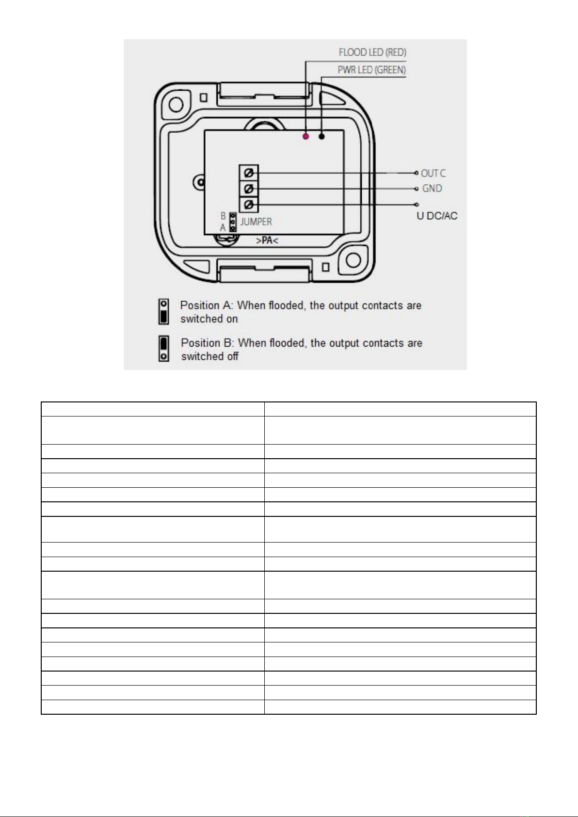
Wiring diagram:
Technical parameters:
Delivery:
Each delivery contains the following unless otherwise agreed by the customer:
•Sensor according to purchase order
•Instruction Manual, including Guarantee Certificate
•Delivery Note
Power supply U
15 to 30 VDC/VAC; recommended 24 VDC/VAC
Temperature range
0 to 80°C around the head
max 100 °C around the sensing electrodes
Output signal
ON/OFF --- relay output
Max. consumption without load
approx. 15 mA
Max. consumption with load
approx. 35 mA
Max. switching current
6 A
Switching voltage
up to 24VDC / 24VAC
Indication
red LED –alarm state
green LED –in operation, inactive alarm state
Switching sensitivity
2 ÷ 5 mS/m
Minimum water conductivity
2 mS/m
Insulation resistance
(between electrodes not connected to PCB)
≥ 500 VDC
Measuring voltage between electrodes
11 VDC
Measuring current between electrodes
0,05 mA
Ingress protection of the head
IP65 according EN 60 529
Electrode material
Stainless steel DIN 1.4301
Diameter / Length of the electrodes
4 mm / 50 mm
Cable length
Head material / Head dimensions
POLYAMID / 90 x 63 x 34 mm
Weight
130 g

Complaints and repairs:
Guarantee and after-guarantee repairs of sensors are ensured by the manufacturer. The product must be delivered
including a copy of the Guarantee Certificate, duly packed and fit to shipment so as not to get damaged during
transportation.
GUARANTEE CERTIFICATE
The product is covered by guarantee for 24 months from the date of purchase.
In this period, the manufacturer will remove all material or manufacturing defects arisen demonstrably during the
applicable warranty period. The manufacturer is liable for the technical and operational parameters of the product given
in the user manual. Any identified defects will be claimed by the buyer without undue delay after their identification or, as
appropriate, after the buyer was able to identify them during his routine care. A completed Warranty Certificate with a
brief description of the defect plus the product must be submitted with the claim.
Warranty does not cover a product:
•That was damaged during transport and inappropriate storage, improper commissioning and/or that has been used for
a purpose other than specified
•That has been used in an improper manner, inconsistent with the user manual and/or generally applicable technical
standards or safety regulations
•That is worn or damaged as a result of normal use of the product, without loss of its operational characteristics and
guaranteed technical parameters
•Into which unskilled intervention, unauthorised structural or other changes (reprogramming, resetting of set
parameters, etc.) have been made
•That is mechanically damaged, e.g. by fall, being hit by a hard object, cleaning with unsuitable agents, power cord
tearing/breaking, breaking or other damage of individual product parts
•That has been exposed to adverse external influence, e.g. object intrusion, wrong supply voltage, influence of
chemical processes, electrical surge (obviously burnt components or printed circuits), dusty, dirty, aggressive or
otherwise unsuitable environment, except normal variation
•That has been damaged by an incidental or natural disaster or as a result of natural or external phenomena, such as
storm, fire, water, excessive heat
•That is claimed without the Warranty Certificate or nameplate.
Rights and obligations regarding the rights arising from defective performance will be governed by the applicable
legislations and the applicable Business Terms and Conditions of SENSIT s.r.o. and this Warranty Certificate.
Date of sale confirmation:
Serial number:
Table of contents
Other Sensit Accessories manuals


