SET POINTS
This feature is useful for tolerance checking (GO/NO GO) or alarm indication in process
control applications. Two limits, high and low, are specified and stored in the non-
volatile memory of the instrument and all readings are compared to these limits. The
results of the comparisons are indicated through the three open-collector outputs
provided on the 9-pin connector, thus
providing "under", "in range" and "over"
signaling. These outputs can be
connected to indicators, buzzers or
relays as required for the application.
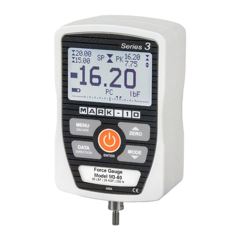
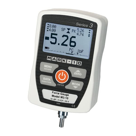
After the Set Point mode is enabled
through the configuration menu (see
Section 3), pressing the MODE key will
sequence through an additional step
indicated by "SP" on the display. To enter
or change the values of the set points
press ENTER. The high set point is
displayed. Use the and keys to increase or decrease the value and MODE for
changing between tension and compression. When the desired value is displayed,
press ENTER and repeat the above steps for the low set point. After entering both
values "donE" will appear on the display. Press ENTER to store the changes or ESCAPE
to quit. In either case "SP" will appear on the display and the ENTER key may be used
for re-entering the set point change mode or the MODE key for proceeding with the
normal operation of the gauge.
AVERAGE MODE
This mode is used for obtaining an average force reading over a specified period of
time. Applications include measurement of peel force, muscle strength, frictional force
and any other tests requiring time-averaged readings. There are three user-program-
mable parameters associated with this mode: trigger force, initial delay and average
time. The programming of these
parameters and the enabling of the
Average mode are done during the
gauge setup. Please refer to the
"Configuration" section for more
information.
Press MODE until "A" is displayed
and then CLEAR or ZERO to begin
testing. The process of averaging
begins as soon as the programmed
trigger force is reached and is
indicated by a flashing "A". The
conclusion of the test is indicated
by an alternating "A" and the calculated value. The readings obtained during the initial
delay will not be part of the average, but the peak value is stored for later recall. A new
test may be started by pressing CLEAR or ZERO.
DELAY AVERAGE TIME
TIME
FORCE
PEAK
AVE
TRIGGER
FORCE
USER - SUPPLIED
40 ma MAX
AS ABOVE
SAME
2N3904
GAUGE
9
8
5
GND
4OUT
_
+
24V MAX
LOAD
Section 6
Section 7
SeriesCG
7
GAUGE CONTROL LANGUAGE
The instrument can be controlled by an external device through the RS-232 channel. The
following is a list of supported commands and their interpretations.All commands must be
terminated with a Carriage Return character (hex 0D) or with a Carriage Return/Line
Feed combination (hex 0D+0A). The gauge responses are always terminated with a
Carriage Return/Line Feed.
A EnableAverage mode
AD Disable Average mode
AM Select Average mode (if enabled)
ATn Average time. n=0.1-300.0 seconds
DELn Initial delay. n=0.1-300.0 seconds
TRFn Trigger force. n=value (+ for compression, - for tension)
SP Enable SetPoint mode
SPD DisableSetPoint mode
SPHn High set point. n=value (+ for compression, - for tension)
SPLn Low set point. n=value (+ for compression, - for tension)
AOFFn Auto-shutoff. n=0,1,5,10,20,30 minutes. 0=always on
AOUTn Auto-transmit every nth reading. n=0,1,2,4,8,16,32,64,128. 0=disabled
LB Switch units to pounds
KG Switch units to kilograms
N Switch units to Newtons
G Switch units grams
ET Enable External trigger mode
ETD Disable External trigger mode
ETE Edge triggered External trigger mode
ETL Level triggered External trigger mode
HL Reading captured on a high to low transition
LH Reading captured on a low to high transition
CUR Current mode (real time display)
PT PeakTensionmode
PC Peak Compressionmode
CLR Clear peaks, start a new average, or external trigger test
Z Zero display and perform the CLR function
? Request the displayed reading
?C Request the current reading
?PT Request the peak tension reading
?PC Request the peak compression reading
?ET Request the reading obtained during the External trigger mode
?A Request the average reading obtained during the Average mode
FLTCn Digital filter for current (displayed readings). n=1,2,4,8
FLTPn Digital filter for peak readings. n=1,2,4,8
FLTAn Analog filter (2.5 Hz). n=1,2. 1=on, 0=off
Section 8
User'sGuide
8
