ASPIRIT ENTERPRISE C6003O User manual

T
Ti
ir
re
e
P
Pr
re
es
ss
su
ur
re
e
M
Mo
on
ni
it
to
or
r
S
Sy
ys
st
te
em
m
C6003O Cars, Pick-ups, SUVs
User Manual
A. Product Overall:
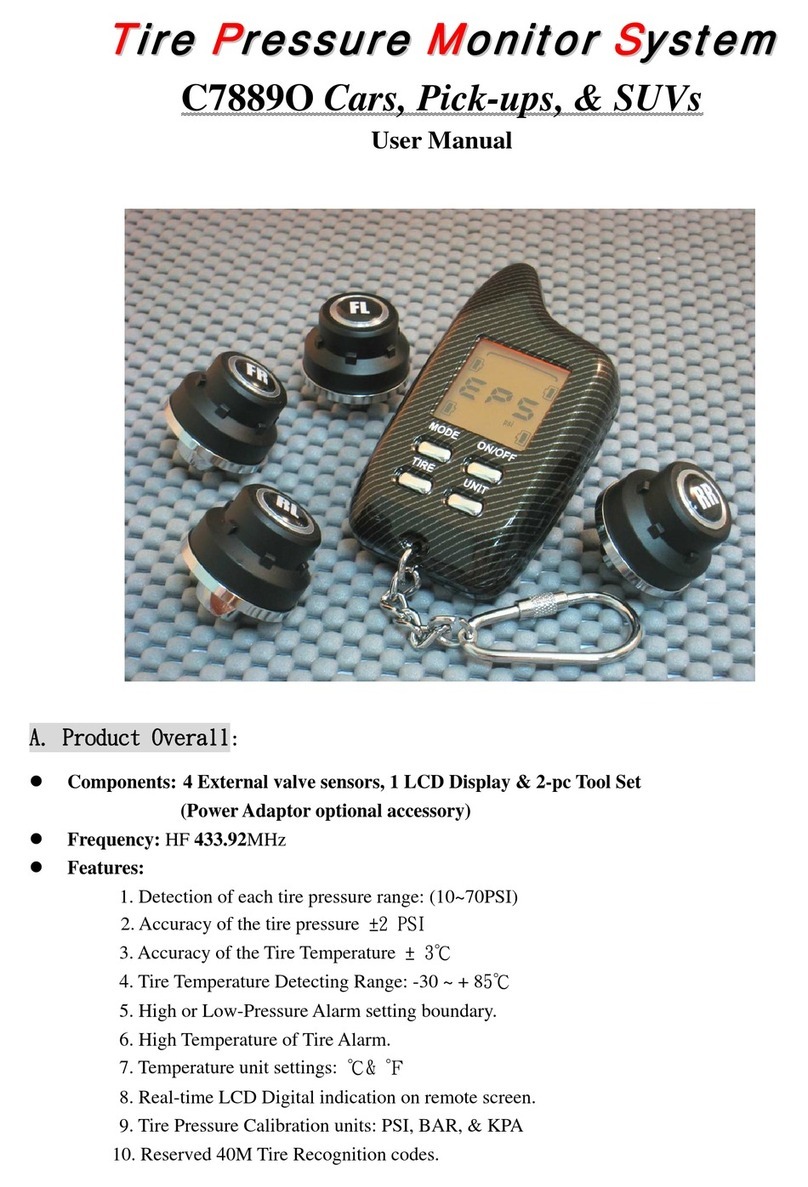
zComponents: 4 External valve sensors, 1 LCD display, & 2-pc Tool set
(PowerAdaptor optional accessory)
zFrequency: HF 433.92MHz
zFeatures:
1. Detection of each tire pressure range: (10~70PSI)
2. Accuracy of the tire pressure ±2 PSI
3. High -Pressure Alarm
4.Low-Pressure Alarm
5. Sensor Low-Battery Alarm.
6. Display Low -Battery Alarm
7. 2 ways of power supplied: Power adaptor or battery application
8. Tire Pressure Calibration Units: PSI , BAR , KPA, Kgf/cm2.
9. Reserved 40M tire recognition codes

zAlarm Types shown on Display:
1. Indication of High-PressureAlarm: LED flashing on specific wheel with High-Pressure value
and “Beep” sound.
2. Indication of Low-PressureAlarm: LED flashing on specific wheel with Low-Pressure value
and “Beep” sound.
3. Indication of Sensor Low-Battery Warning: Red Light on Power & LED on specific wheel on
display panel.
4. Indication of Display Low-Battery Warning: LED flashing indication on the Power light &
“Beep” sound.
zSpecification:
Sensors LCD Display
Dimension ψ22.3* H: 22.5 ±0.5 (mm) 76mm (L) x 42.5mm (W) x 19.5mm (H)
Weight 10.0g ± 0.5g ( w/Battery contained) 36.5g ± 0.5g (Battery Excluded)
Power Supply 3V Lithium CR1632
(1~2 year Lifetime or above 2 years when
under normal condition)
2 x 3A’ BatteryAlkaline type or
(Power Supplied line 12V)
Frequency 433.92MHz 433.92MHz
Operating
Temperature
-30℃~ + 85℃-20℃~+80℃
*Specification is subject to change for product performance without any notice
B. Installation:(Always have the display power on before installation of sensors)
Sensor Indication:
1. Labeled w/ FL: Front Left Wheel
2. Labeled w/ FR: Front Right Wheel
3. Labeled w/ RL: Rear Left Wheel.
4. Labeled w/ RR: Rear Right Wheel
Installation Process:
For Sensors:
1. Make sure the top and bottom are tighten on the sensors
(Applied with enclosed wrench)
2. Remove the original valve from stem。
3. Testing the pressure by applying Tire Gauges.(The suggested pressure value
can be referred to Car user manual to ensure proper pressure).
4. Screw-on the enclosed Hex nut on the valve; then, mount the valve
sensors onto the valve stem. Make sure the Hex nut is being tighten in reverse
clockwise direction to affix with the bottom part of the Valve Sensors。
NOTICE: To Check the valve if it is leaking after installation
,it can be confirmed from the display to see if the
pressure has dropped down.
For LCD Display:
1. Place the LCD display at best view place, then, have the
display power ON (or plugging DC12V supplied cord into cigarette part)
SUGGESTION: Make sure the display power is on to confirm the communication of sensor & display
is normal。

C. Illustration on the LCD Display:
ON/OFF: Power ON or OFF.
CLEAR: Press this button when there is
abnormal alarm or in “MUTE”
To clear the abnormal indication,
press this button for 2~3 seconds.
◎The very 2 down buttons have no use/application so far.
D: Explanation of Circumstances:
◎POWER is OFF ◎POWER on---“Detecting” ◎Display under Low-Battery
1. 2. 3. 4.
◎Most-seen situations about sensors on display:
Pic.1. Sensor-Front Left Wheel pressure problem.
Pic.2. Sensor-Front Right Wheel pressure problem.
Pic.3. Sensor-Rear Left Wheel pressure problem
Pic.4. Sensor-Rear Right Wheel pressure problem.
Pic.5. Sensor Low-Battery: Front Right Wheel LED
On & POWER Red light on
5. 5-1. *(Pic. 5 & 5-1 scenarios interchanged when display
Powerisinaregularmode)
COWEAHTH PRECISION TECH. CO., LTD.
ASPIRIT ENTERPRISE, INC.
Email:tire.monitor@msa.hinet.net

T
Ti
ir
re
e
P
Pr
re
es
ss
su
ur
re
e
M
Mo
on
ni
it
to
or
r
S
Sy
ys
st
te
em
m
M6003O Motorbike
User Manual
A. Product Overall:
zComponents: 2 External valve sensors, 1 LCD display, & 2-pc Tool set
(PowerAdaptor optional accessory)
zFrequency: HF 433.92MHz
zFeatures:
1. Detection of each tire pressure range: (10~70PSI)
2. Accuracy of the tire pressure ±2 PSI
3. High -Pressure Alarm
4.Low-Pressure Alarm
5. Sensor Low-Battery Alarm.
6. Display Low -Battery Alarm
7. 2 ways of power supplied: Power adaptor or battery application
8. Tire Pressure Calibration Units: PSI , BAR , KPA, Kgf/cm2.
9. Reserved 40M tire recognition codes

zAlarm Types shown on Display:
1. Indication of High-PressureAlarm: LED flashing on specific wheel with High-Pressure value
and “Beep” sound.
2. Indication of Low-PressureAlarm: LED flashing on specific wheel with Low-Pressure value
and “Beep” sound.
3. Indication of Sensor Low-Battery Warning: Red Light on Power & LED on specific wheel on
display panel.
4. Indication of Display Low-Battery Warning: LED flashing indication on the Power light &
“Beep” sound.
zSpecification:
*Specification is subject to change for product performance without any notice
B. Installation:(Always have the display power on before installation of sensors)
Sensor Indication:
1. Labeled w/ F.: Front Wheel
2. Labeled w/ R.: Rear Wheel.
Installation Process:
SUGGESTION: Make sure the display power is on so the
communication of sensor & display is normal prior to the installation of sensor。
For Sensors:
1. Make sure the top and bottom are tighten on the sensors
(Applied with enclosed wrench)
2. Remove the original valve from stem。
3. Testing the pressure by applying Tire Gauges.(The suggested pressure value
can be referred to Car user manual to ensure proper pressure).
4. Screw-on the enclosed Hex nut on the valve; then, mount the valve
sensors onto the valve stem. Make sure the Hex nut is being tighten in reverse
clockwise direction to affix with the bottom part of the Valve Sensors。
NOTICE: To Check the valve if it is leaking after installation
,it can be confirmed from the display to see if the
pressure has dropped down.
For LCD Display:
1. Place the LCD display at best view place, then, have the
display power ON (or applying Motorbike DC12V power wire)
Sensors LCD Display
Dimension ψ22.3* H: 22.5 ±0.5 (mm) 76mm (L) x 42.5mm (W) x 19.5mm (H)
Weight 10.0g ± 0.5g ( w/Battery contained) 36.5g ± 0.5g (Battery Excluded)
Power Supply 3V Lithium CR1632
(1~2 year Lifetime or above 2 years when
under normal condition)
2 x 3A’ BatteryAlkaline type or
(Power Supplied line 12V)
Frequency 433.92MHz 433.92MHz
Operating
Temperature
-30℃~ + 85℃-20℃~+80℃

C. Illustration on the LCD Display:
ON/OFF: Power ON or OFF.
CLEAR: Press this button when there is
abnormal alarm or in “MUTE”
To clear the abnormal indication,
press this button for 2~3 seconds.
◎The very 2 down buttons have no use/application so far.
D: Explanation of Circumstances:
◎POWER is OFF ◎POWER on---“Detecting” ◎Display under Low-Battery
1. 2. 3. 3-1.
◎Most-seen situations about sensors on display:
Pic.1. Sensor-Front Wheel pressure problem.
Pic.2. Sensor-Rear Wheel pressure problem.
Pic.3. Sensor Low-Battery: Front Right Wheel LED on & POWER Red light on
*(Pic. 3 & 3-1 scenarios interchanged when display power is in a regular mode)
COWEAHTH PRECISION TECH. CO., LTD.
ASPIRIT ENTERPRISE, INC.
Email:tire.monitor@msa.hinet.net

Notice : The changes or modifications not expressly approved by the party responsible
for compliance could void the user’s authority to operate the equipment.
IMPORTANT NOTE: To comply with the FCC RF exposure compliance requirements, no
change to the antenna or the device is permitted. Any change to the antenna or the device
could result in the device exceeding the RF exposure requirements and void user’s
authority to operate the device.
This manual suits for next models
1
Table of contents
Other ASPIRIT ENTERPRISE Measuring Instrument manuals
Popular Measuring Instrument manuals by other brands

EXFO
EXFO IQS-12008 user guide

Endress+Hauser
Endress+Hauser Proline Promass 80 Description of Device Functions

Combined Energy
Combined Energy CET-HD-PM2-1 Product user manual

JENCO
JENCO 6179M Operation manual

Sloan
Sloan TruFlush TRF 156 Repair Parts and Maintenance Guide

Quantel Medical
Quantel Medical Optimus II Service manual