Sensitron STS3REL User manual

Manuale d’istruzione / Instruction Manual
MT3678 Rev.6 02/05/2022
©2022 SENSITRON S.R.L. - All rights reserved - www. sensitron.it
Scheda a tre relè per SMART3 e SMARTS /
Three-relay card for SMART3 and SMARTS
STS3REL

THIS MANUAL MUST BE CAREFULLY READ BY ALL PERSONS WHO HAVE OR
WILL HAVE THE RESPONSIBILITY FOR INSTALLING, USING OR SERVICING
THIS PRODUCT.
Like any equipment, this product will perform as designed only if installed,
used and serviced in accordance with the manufacturer’s instructions.
OTHERWISE, IT COULD FAIL TO PERFORM AS DESIGNED AND PERSONS
WHO RELY ON THIS PRODUCT FOR THEIR SAFETY COULD SUFFER SEVERE
PERSONAL INJURY OR DEATH.
The warranties made by Sensitron s.r.l. with respect to this product are
voided if the product is not installed, used and serviced in accordance with
the instructions in this user guide. Please protect yourself and others by
following them.
We recommend our customers to write or call us regarding this equipment
prior to use or for any additional information relative to use or repair.
QUESTO MANUALE DEVE ESSERE LETTO ATTENTAMENTE DATUTTI COLORO
CHE HANNO O AVRANNO LA RESPONSABILITA’ DI INSTALLARE, UTILIZZARE
O DI PRESTARE UN SERVIZIO DI ASSISTENZA SU QUESTO PRODOTTO.
Come ogni componente di un sistema, questo prodotto funzionerà corret-
tamente solo se installato, utilizzato e controllato come prescritto dal fab-
bricante.
IN CASO CONTRARIO, POTREBBE NON FUNZIONARE CORRETTAMENTE E LE
PERSONE CHE AFFIDANO LA LORO SICUREZZA A QUESTO PRODOTTO PO-
TREBBERO SUBIRE DANNI PERSONALI O LETALI.
La garanzia riconosciuta da Sensitron s.r.l. su questo prodotto potrebbe
essere nulla se il prodotto non venisse installato, utilizzato e controllato
secondo le istruzioni fornite con il presente manuale. Per favore, protegge-
tevi seguendole attentamente.
Invitiamo i nostri clienti a scriverci o a chiamarci per ogni informazione ri-
guardo questo strumento, il suo uso o una sua eventuale riparazione.

ItalianoEnglish
SUMMARY
1. Introduction..................................................................................................... 3
2. Technical specications............................................................................... 3
3. Layout and conguration ........................................................................... 3
4. Assembly........................................................................................................... 4
SOMMARIO
1. Introduzione.................................................................................................... 1
2. Caratteristiche tecniche............................................................................... 1
3. Layout e congurazione.............................................................................. 1
4. Montaggio........................................................................................................ 2

ITALIANO
Pag. 1
1. Introduzione
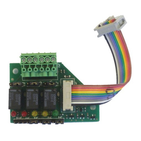
La scheda a 3 relè (STS3REL) per rilevatori gas della serie SMART3/SMART S permette di otte-
nere delle uscite con contatti puliti liberi da tensione.
• La prima uscita è associata alla segnalazione di Fault e di Watch-dog
• La seconda uscita è associabile all’allarme 1 o all’allarme 2 del rilevatore
• La terza uscita è associabile all’allarme 2 o all’allarme 3 del rilevatore
La scheda è dotata di un cavo at con connettore per l’inserimento nell’apposito connettore
presente sulla scheda base del rilevatore.
Quando utilizzata con rilevatori serie SMART S la funzione associata ai 3 relè può essere mo-
dicata nel rilevatore.
2. Caratteristiche tecniche
Portata contatto relè: 1A a 24 Vdc / 0.5A a 125Vac.
La scheda STS3REL è progettata con lo scopo di poter essere inserita anche in sistemi dove
è richiesto un livello di sicurezza funzionale SIL2. Per garantire questa caratteristica sono
necessari tre passaggi:
• I relè devono essere normalmente energizzati.
• Durante l’installazione deve essere collegato all’uscita di ogni relè un fusibile a 1.33 A.
• Vericare il funzionamento dei contatti relè almeno una volta all’anno, testando il rile-
vatore in gas e vericando lo scatto dei relè.
La tabella seguente riporta i dati di adabilità della scheda STS3REL:
PFD λs [1/h] λdd [1/h] λdu [1/h] T1 MTTR
4,36E-05 2,28E-08 0,00E+00 9,90E-09 1 anno 24h
3. Layout e congurazione
JP9 JP6 JP4
RELÈ 3RELÈ 2
RELÈ 1
DL1 DL3 DL2 DL4 DL5
JP8JP5JP3
6
1
JP2: Connettore relè
COM1
S1
COM2
S2
COM3
S3
1 1 1
1 1
JP2
JP1
JP4: sicurezza relè
Chiuso (default): normalmente non energizzati
Aperto: normalmente energizzati
JP9:
1-2 chiusi: relè 3 su allarme 2
2-3 chiusi (default): relè 3 su allarme 3
JP6:
1-2 chiusi: relè 2 su allarme 1
2-3 chiusi (default): relè 2 su allarme 2
JP3, JP5 e JP8: segnale relè 1, 2 e 3
1-2 chiusi: normalmente chiuso
2-3 chiusi (default): normalmente aperto
JP1: Connettore scheda base
DL1 LED verde - acceso quando scheda alimentata
DL2 LED giallo - acceso quando errore nel watchdog
DL3 LED giallo - acceso quando rilevatore in fault
DL4 LED rosso - acceso per allarme 1 o 2
DL5 LED rosso - acceso per allarme 2 o 3
JP9 JP6 JP4
RELAY
3
RELAY
2
RELAY
1
DL1 DL3 DL2 DL4 DL5
JP8JP5JP3
6
1
JP2: Relays connector
COM1
S1
COM2
S2
COM3
S3
1 1 1
JP2
JP1
JP4: security of relays
Closed (default): normallly not energized
Open: normally energized
JP9:
1-2 closed: relay 3 for alarm 2
2-3 closed (default): relay 3 for alarm 3
JP6:
1-2 closed: relay 2 for alarm 1
2-3 closed (default): relay 2 for alarm 2
JP3, JP5 and JP8: signal of relays 1, 2 and 3
1-2 closed: normally closed
2-3 chiusi (default): normally open
JP1: Main board connector
DL1 green LED - ON when the device is powered ON
DL2 yellow LED - ON when watchdog error
DL3 yellow LED - ON when fault
DL4 red LED - ON when alarm 1 or 2
DL5 red LED - ON when alarm 2 or 3
123 123 12
1 1
123 123 12

ITALIANO
Pag. 2
Figura 1) Montaggio scheda relé sulla scheda SMART3
Figura 2) Montaggio scheda relé sulla scheda SMART S
4. Montaggio
1. Il montaggio della STS3REL deve essere eettuato con il rilevatore spento. Inserire le
colonnine nei fori presenti sul circuito base del rilevatore dove indicato.
2. Inserire il connettore posto all’ estremità del cavo at della scheda 3 relè nel connet-
tore apposito presente sulla base dello SMART; rivolgere la sporgenza presente sul
connettore verso l’ interno del circuito. Vedere gure 1 e 2.
3. Avvitare le viti sulle colonnine in modo da ssare la scheda relè. Ultimato il montaggio
si noterà che la morsettiera è rivolta verso l’alto, ossia verso la morsettiera del rilevatore
4. Eettuare i cablaggi.
5. Accendere il rilevatore.
Per i rivelatori della serie SMART3: per il corretto funzionamento della scheda STS3REL, è
necessario aprire il jumper JP5-6 posizionato sulla scheda base del rivelatore (vedi manuale
SMART3).
IMPORTANTE!

ENGLISH
Pag. 3
1. Introduction
The three-relay card (STS3REL) for SMART3/SMART S gas detectors allows the detector to be
provided with tension free changeover contacts.
• The rst output is to be associated to the Fault and Watch-dog alarm
• The second output can be associated to the rst or second alarm threshold
• The third output can be associated to the second or third alarm threshold.
The card comes complete with a at cable and connector to be easily plugged on the detec-
tor’s main board.
When used with the SMART S detector, the function of the relays can be modied by the
detector’s operating menu.
2. Technical specications
Relays contact ratings: 1A a 24 Vdc / 0.5A a 125Vac.
STS3REL board is designed to be installed in systems with a functional safety SIL2. In order
to guarantee this capability the following settings must be implemented
• Relays must be set as normally energized.
• Duringt installation step, connect a 1.33A fuse to each relay’s output.
• Check the relays functionality at least one time per year, by testing detector response
with gas application and checking the relays activation.
The following table describes the STS3REL safety parameters:
PFD λs [1/h] λdd [1/h] λdu [1/h] T1 MTTR
4,36E-05 2,28E-08 0,00E+00 9,90E-09 1 year 24h
3. Layout and conguration
JP9 JP6 JP4
RELÈ 3RELÈ 2
RELÈ 1
DL1 DL3 DL2 DL4 DL5
JP8JP5JP3
6
1
JP2: Connettore relè
COM1
S1
COM2
S2
COM3
S3
1 1 1
1 1
JP2
JP1
JP4: sicurezza relè
Chiuso (default): normalmente non energizzati
Aperto: normalmente energizzati
JP9:
1-2 chiusi: relè 3 su allarme 2
2-3 chiusi (default): relè 3 su allarme 3
JP6:
1-2 chiusi: relè 2 su allarme 1
2-3 chiusi (default): relè 2 su allarme 2
JP3, JP5 e JP8: segnale relè 1, 2 e 3
1-2 chiusi: normalmente chiuso
2-3 chiusi (default): normalmente aperto
JP1: Connettore scheda base
DL1 LED verde - acceso quando scheda alimentata
DL2 LED giallo - acceso quando errore nel watchdog
DL3 LED giallo - acceso quando rilevatore in fault
DL4 LED rosso - acceso per allarme 1 o 2
DL5 LED rosso - acceso per allarme 2 o 3
JP9 JP6 JP4
RELAY
3
RELAY
2
RELAY
1
DL1 DL3 DL2 DL4 DL5
JP8JP5JP3
6
1
JP2: Relays connector
COM1
S1
COM2
S2
COM3
S3
1 1 1
JP2
JP1
JP4: security of relays
Closed (default): normallly not energized
Open: normally energized
JP9:
1-2 closed: relay 3 for alarm 2
2-3 closed (default): relay 3 for alarm 3
JP6:
1-2 closed: relay 2 for alarm 1
2-3 closed (default): relay 2 for alarm 2
JP3, JP5 and JP8: signal of relays 1, 2 and 3
1-2 closed: normally closed
2-3 chiusi (default): normally open
JP1: Main board connector
DL1 green LED - ON when the device is powered ON
DL2 yellow LED - ON when watchdog error
DL3 yellow LED - ON when fault
DL4 red LED - ON when alarm 1 or 2
DL5 red LED - ON when alarm 2 or 3
123 123 12
1 1
123 123 12

ENGLISH
Pag. 4
Figure 1) Assembly of the relay card on the SMART3 main board
Figure 2) Assembly of the relay card on the SMART S main board
4. Assembly
1. Verify the detector has been disconnected before mounting the STS3REL.
2. Insert the supports into the holes on the PCB.
3. Insert the female connector at the edge of the at cable into the male connector on
the main PCB of the detector (see gure 1 and 2 below). Beware that the black triangle
on the female connector (corresponding to pin one) is facing towards the internal part
of the PCB.
4. Tighten the card to the supports with the screws of the relay card.
5. Once the card has been properly mounted the terminal block shall be faced towards
the upper part of the detector, i.e. towards the detector terminal block.
6. The detector can now be wired, connected and powered on.
For the SMART3’s series detectors, in order to properly activate the ST.S3REL card, it is man-
datory to open the jumper JP5-6 on the detector’s main PCB (refer to the SMART3’s detector
manual).
IMPORTANT!

Contact details: SENSITRON s.r.l. Viale della Repubblica, 48 - 20007 - Cornaredo (MI) Italy
LEADER IN SIL2 (SIL3) FIXED GAS DETECTION SYSTEMS
Other manuals for STS3REL
2
Table of contents
Other Sensitron Relay manuals
