Sensitron STS1REL User manual

Manuale d’istruzione / Instruction Manual
MT1071 rev. 4 10/12/2020
©2020 SENSITRON S.R.L. - All rights reserved - www. sensitron.it
Scheda a un relè per SMART3 / One relay card for SMART3
STS1REL

THIS MANUAL MUST BE CAREFULLY READ BY ALL PERSONS WHO HAVE OR
WILL HAVE THE RESPONSIBILITY FOR INSTALLING, USING OR SERVICING
THIS PRODUCT.
Like any equipment, this product will perform as designed only if installed,
used and serviced in accordance with the manufacturer’s instructions.
OTHERWISE, IT COULD FAIL TO PERFORM AS DESIGNED AND PERSONS
WHO RELY ON THIS PRODUCT FOR THEIR SAFETY COULD SUFFER SEVERE
PERSONAL INJURY OR DEATH.
The warranties made by Sensitron s.r.l. with respect to this product are
voided if the product is not installed, used and serviced in accordance with
the instructions in this user guide. Please protect yourself and others by
following them.
We recommend our customers to write or call us regarding this equipment
prior to use or for any additional information relative to use or repair.
QUESTO MANUALE DEVE ESSERE LETTO ATTENTAMENTE DA TUTTI COLORO
CHE HANNO O AVRANNO LA RESPONSABILITA’ DI INSTALLARE, UTILIZZARE
O DI PRESTARE UN SERVIZIO DI ASSISTENZA SU QUESTO PRODOTTO.
Come ogni componente di un sistema, questo prodotto funzionerà corret-
tamente solo se installato, utilizzato e controllato come prescritto dal fab-
bricante.
IN CASO CONTRARIO, POTREBBE NON FUNZIONARE CORRETTAMENTE E LE
PERSONE CHE AFFIDANO LA LORO SICUREZZA A QUESTO PRODOTTO PO-
TREBBERO SUBIRE DANNI PERSONALI O LETALI.
La garanzia riconosciuta da Sensitron s.r.l. su questo prodotto potrebbe
essere nulla se il prodotto non venisse installato, utilizzato e controllato
secondo le istruzioni fornite con il presente manuale. Per favore, protegge-
tevi seguendole attentamente.
Invitiamo i nostri clienti a scriverci o a chiamarci per ogni informazione ri-
guardo questo strumento, il suo uso o una sua eventuale riparazione.

ItalianoEnglish
SUMMARY
1. Introduction..................................................................................................... 3
2. Technical specications and layout ........................................................ 3
3. Assembly........................................................................................................... 3
SOMMARIO
1. Introduzione.................................................................................................... 1
2. Caratteristiche tecniche e layout ............................................................. 1
3. Montaggio........................................................................................................ 1

ITALIANO
Pag. 1
1. Introduzione
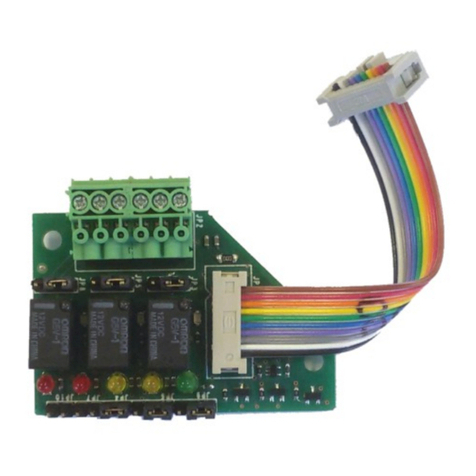
La scheda a 1 relè (STS1REL) per rilevatori della serie SMART3 permette di ottenere un’uscita
con contatto pulito libero da tensione.
2. Caratteristiche tecniche e layout
Portata contatto relè: 50 mA a-24 Vdc; 100 mA a 12Vdc
Figura 1) Layout della scheda STS1REL
3. Montaggio
Il montaggio della STS1REL deve essere eettuato con il rilevatore spento. Inserire la scheda
ad innesto verticale nel connettore lasciando liberi i 2 morsetti più a sinistra del connettore
a 10 poli; assicurarsi che la scheda si sia innestata no a fondo corsa.
Il LED rosso presente sulla scheda seriale deve essere rivolto verso la morsettiera generale
come indicato nella gura 2.
Per i rivelatori della serie SMART3G, per il corretto funzionamento della scheda opziona-
le STS1REL, è necessario aprire il jumper JP5-6 posizionato sulla scheda base del rivelatore
(vedi manuale SMART3G).
IMPORTANTE!
C
C
H
H
I
I
U
U
S
S
O
O
:
:
R
R
E
E
L
L
E
E
’
’
N
N
O
O
R
R
M
M
A
A
L
L
M
M
E
E
N
N
T
T
E
E
E
E
C
C
C
C
I
I
T
T
A
A
T
T
O
O
(
(
D
D
E
E
F
F
A
A
U
U
L
L
T
T
)
)
A
A
P
P
E
E
R
R
T
T
O
O
:
:
R
R
E
E
L
L
E
E
’
’
N
N
O
O
R
R
M
M
A
A
L
L
M
M
E
E
N
N
T
T
E
E
D
D
I
I
S
S
E
E
C
C
C
C
I
I
T
T
A
A
T
T
O
O
Jp4
Relé
Jp4
J
J
U
U
M
M
P
P
E
E
R
R
T
T
R
R
A
A
1
1
E
E
2
2
C
C
O
O
N
N
T
T
A
A
T
T
T
T
O
O
N
N
O
O
R
R
M
M
A
A
L
L
M
M
E
E
N
N
T
T
E
E
A
A
P
P
E
E
R
R
T
T
O
O
(
(
N
N
A
A
)
)
J
J
U
U
M
M
P
P
E
E
R
R
T
T
R
R
A
A
2
2
E
E
3
3
,
,
C
C
O
O
N
N
T
T
A
A
T
T
T
T
O
O
N
N
O
O
R
R
M
M
A
A
L
L
M
M
E
E
N
N
T
T
E
E
C
C
H
H
I
I
U
U
S
S
O
O
(
(
N
N
C
C
)
)
(
(
D
D
E
E
F
F
A
A
U
U
L
L
T
T
)
)
Jp3
1
2
3
Jp3
LED: ACCESO CON RELE’ ECCITATO
1
2
3
1
2
3

ITALIANO
Pag. 2
1
1
2
2
3
3
4
4
5
5
6
6
15
37
26
48
1
1
2
2
3
3
4
4
5
5
6
6
15
37
26
48
SCHEDA
STS1REL
Circuito Smart 3
Relé
LED
Uscita contatto relè
WD/Fault e nessun allarme
Modalità di attivazione del relè
WD/Fault e allarme 2
WD/Fault e allarme 3
WD/Fault e allarme 3
7
8
7
8
7
8
7
8
Nota: Indipendentemente dalla configurazione dei dip switch, all’accensione per 80 sec. il relè segnalerà sempre il guasto
WD= Watch Dog
Figura 2) Montaggio scheda relè e impostazioni jumper

ENGLISH
Pag. 3
1. Introduction
The 1 relay card (STS1REL) for the SMART3 series gas detectors allows the detector to be
provided with 1 voltage free changeover contact.
2. Technical specications and layout
Contact rating: 50 mA at 24 Vdc; 100 mA at 12 Vdc
Figure 1) Layout of the STS1REL card
3. Assembly
Before inserting the STS1REL card, be sure the detector has been powered o. Insert the
vertical plug-in card into the 10-pole connector, paying attention to leave the two left side
poles free. Make sure the card has been fully plugged in.
Turn the side comprising the red LED towards the main terminal board, as shown in gure 2.
for the SMART3G’s series, in order to properly activate the STS1REL relay card it is manda-
tory to open the jumper JP5-6 on the detector’s main PCB (refer to the SMART3G’s detector
manual).
IMPORTANT!
C
C
L
L
O
O
S
S
E
E
D
D
:
:
N
N
O
O
R
R
M
M
A
A
L
L
L
L
Y
Y
E
E
N
N
E
E
R
R
G
G
I
I
Z
Z
E
E
D
D
R
R
E
E
L
L
A
A
Y
Y
(
(
D
D
E
E
F
F
A
A
U
U
L
L
T
T
)
)
O
O
P
P
E
E
N
N
:
:
N
N
O
O
R
R
M
M
A
A
L
L
L
L
Y
Y
D
D
E
E
-
-
E
E
N
N
E
E
R
R
G
G
I
I
Z
Z
E
E
D
D
R
R
E
E
L
L
A
A
Y
Y
Jp4
Relay
Jp4
N
N
O
O
R
R
M
M
A
A
L
L
L
L
Y
Y
O
O
P
P
E
E
N
N
(
(
N
N
O
O
)
)
C
C
O
O
N
N
T
T
A
A
C
C
T
T
I
I
F
F
J
J
U
U
M
M
P
P
E
E
R
R
B
B
E
E
T
T
W
W
E
E
E
E
N
N
1
1
A
A
N
N
D
D
2
2
N
N
O
O
R
R
M
M
A
A
L
L
L
L
Y
Y
C
C
L
L
O
O
S
S
E
E
D
D
(
(
N
N
C
C
)
)
C
C
O
O
N
N
T
T
A
A
C
C
T
T
I
I
F
F
J
J
U
U
M
M
P
P
E
E
R
R
B
B
E
E
T
T
W
W
E
E
E
E
N
N
2
2
A
A
N
N
D
D
3
3
(
(
D
D
E
E
F
F
A
A
U
U
L
L
T
T
)
)
Jp3
1
2
3
Jp3
LED: LIT WHEN THE RELAY IS ENERGIZED
1
2
3
1
2
3

ENGLISH
Pag. 4
1
1
2
2
3
3
4
4
5
5
6
6
15
37
26
48
1
1
2
2
3
3
4
4
5
5
6
6
15
37
26
48
STS1REL
BOARD
Smart 3 PCB
Relay
LED
Output relay contact
WD/Fault and no alarm
Relay activation mode
WD/Fault and alarm 2
WD/Fault and alarm 3
WD/Fault and alarm 3
7
8
7
8
7
8
7
8
Note: During start up condition (80 sec) the relay output is in Fault
WD= Watch Dog
Figure 2) Assembly of the relay card and jumper settings

Contact details: SENSITRON s.r.l. Viale della Repubblica, 48 - 20007 - Cornaredo (MI) Italy
LEADER IN SIL2 (SIL3) FIXED GAS DETECTION SYSTEMS
Table of contents
Languages:
Other Sensitron Relay manuals
Popular Relay manuals by other brands
Chenzhu
Chenzhu GS8500 EX Series user manual

Woodward
Woodward MFR 11 manual
Siemens
Siemens 3RB22 Equipment manual
KAEL
KAEL ke-FKR4 quick start guide

Schweitzer Engineering Laboratories
Schweitzer Engineering Laboratories SEL-251D-1 instruction manual

Vantage Hearth
Vantage Hearth RadioLink AccentPoint Relay Station II APREL installation manual

