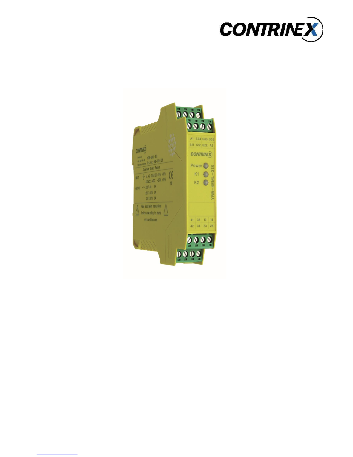
Application manual for YRB-4EML-31S safety relay
Contrinex AG Industrial Electronics 5
Table of contents
1 Introduction..................................................................................................................................................... 7
1.1 Target group for this application manual................................................................................................ 7
2 Safety of machines and systems ..................................................................................................................... 9
2.1 Functional safety ................................................................................................................................... 10
2.2 Practical procedure according to EN ISO
13849
................................................................................... 10
2.2.1 Definition of the safety function ................................................................................................... 10
2.2.2 Determination of the required performance level (PL
r
)
.............................................................. 11
2.2.3 Technical implementation............................................................................................................. 11
2.2.4 Dividing the safety function into subsystems ................................................................................ 12
2.2.5 Determination of the achieved PL for each subsystem................................................................. 12
2.2.6 Determination of the achieved PL for the overall safety function................................................ 14
2.2.7 Verification of the achieved PL...................................................................................................... 14
2.2.8
V
alidatio
n
...................................................................................................................................... 14
2.3 Practical procedure according to EN ISO
62061
................................................................................... 15
2.3.1 Specification of requirements for the safety-related control function (SRCF)............................... 15
2.3.2 Determination of the required safety integrity level
(SIL)
............................................................ 15
2.3.3 Drafting the safety-related electrical control system ................................................................... 15
(SRECS) .......................................................................................................................................................... 15
2.3.4 Determination of the achieved safety integrity for the entire SRECS........................................... 16
2.3.5 Verification of the achieved SIL...................................................................................................... 16
2.3.6
V
alidatio
n
...................................................................................................................................... 17
3 Safety technology basics ............................................................................................................................... 18
3.1 Cross-circuit detection .......................................................................................................................... 18
3.2 Maximum cable lengths ........................................................................................................................ 19
3.3 Stop ....................................................................................................................................................... 20
4 Application examples for YRB-4EML-31S safety relay .................................................................................. 22
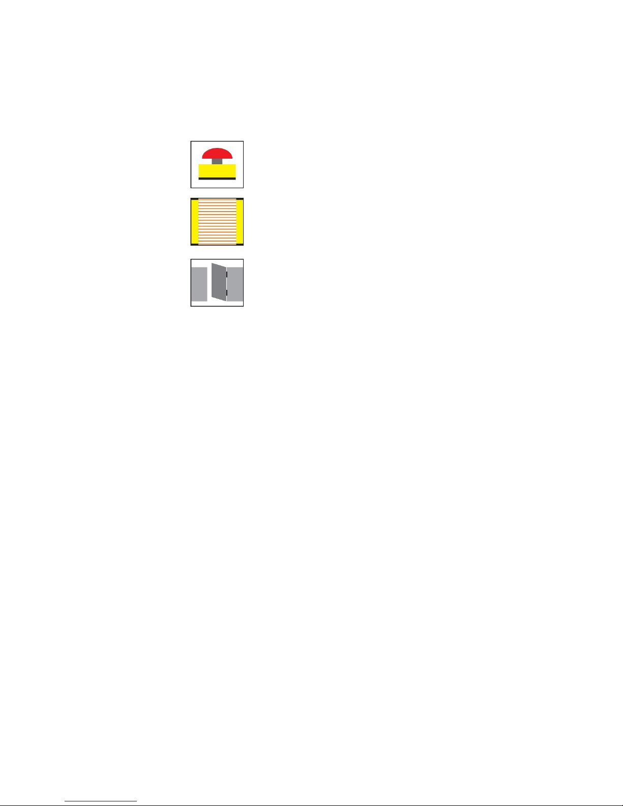
4.1 Emergency stop..................................................................................................................................... 22
4.1.1 YRB-4EML-31S up to PL c/SIL
1
...................................................................................................... 23
4.1.2 YRB-4EML-31S up to PL d/SIL
2
..................................................................................................... 25
4.2 Light curtain (ESPE)................................................................................................................................ 27