sensl HRM-TDC User manual

USER MANUAL
HRM-TDC
SensL © 2011 1
High Resolution Time-to-Digital Converter Module
Document Overview
This document provides the user with a comprehensive
description of the hardware and software of the HRM-
TDC module, including system description, the various
timing modes, software GUI and DLL drivers. The
document is split up into the following sections:
GETTING STARTED
This section provides instructions for unpacking the HRM-TDC and a brief overview.
SYSTEM DESCRIPTION
This section gives a description of the system hardware, the various ports and communication channels, the internal
processor, and the specic timing features.
SENSL INTEGRATED ENVIRONMENT (SIE)
The SIE is a user interface for setting up and controlling the HRM-TDC module. While the interface provides an
extensive range of operating modes and measurement processes, including graphical presentation, it does not fully
cover all features available in the HRM-TDC module. This section of the User Manual includes instructions for the
installation of the necessary software, and detailed description of each part of the SIE and how to set up and use it.
APPENDIX
The HRM-TDC DLL provides a set of functions that will allow full control of the HRM-TDC for all features. For
complex experiments that require control beyond the scope of the SIE, it is expected that the user will write their own
real-time application utilizing the various functions in this DLL. The Appendix of the User Manual covers Registers,
low level DLL functions, high level DLL functions, DLL error reporting and examples, as well as help and examples
for resolving time-tag values,an explanation of the correlation function used and the Labview drivers provided.

SensL © 2011 2
USER MANUAL
HRM-TDC
SensL © 2011 2
> Contents > Getting Started
Contents
Document Overview.................................................................................................................................. 1
Glossary..................................................................................................................................................... 5
Getting Started.......................................................................................................................................... 6
Contact & Support................................................................................................................................. 6
Unpacking the System and Preparing for Use........................................................................................ 6
Safety Considerations............................................................................................................................ 6
System Installation Procedures .............................................................................................................. 6
Signal Inputs and Outputs ..................................................................................................................... 8
I/O Port Connector Pin Allocation .......................................................................................................... 8
HRM-TDC System Description................................................................................................................. 9
Block Diagram....................................................................................................................................... 9
Memory ........................................................................................................................................ 9
Time-to-Digital Converter Module ................................................................................................. 9
High Speed USB 2.0 Interface ...................................................................................................... 9
16-Bit General Purpose I/O Port ................................................................................................... 10
System Processor and Controller.................................................................................................. 10
System Processor and Controller Detailed Description........................................................................... 10
Command Interpreter.................................................................................................................... 10
DMA to USB Fast Transfer Interface.............................................................................................. 11
Time-Bin and Time-Tag Controller................................................................................................. 11
Data Router Module...................................................................................................................... 11
Address Router Module ................................................................................................................ 11
Dual Port Memory Arbiter ............................................................................................................. 11
HRM-TDC Specic Feature Overview .................................................................................................... 12
HISTOGRAM ................................................................................................................................ 13
FIFO ............................................................................................................................................. 13
Histogram – Single-stop (“TCSPC” MODE) ............................................................................................ 14
Histogram – Multi-stop (“Multiscaler/Counter”)....................................................................................... 15

SensL © 2011 3
USER MANUAL
HRM-TDC
SensL © 2011 3
> Contents > Getting Started
FIFO – Single-stop (“TCSPC - with Macro-Time”)................................................................................... 16
FIFO – Multi-stop (“FIFO - Time Tagging”) .............................................................................................. 17
SensL Integrated Environment (SIE) ........................................................................................................ 18
System Requirements............................................................................................................................ 18
Installation ............................................................................................................................................. 18
Using the SensL Integrated Environment (SIE) ....................................................................................... 19
Main Page .................................................................................................................................... 19
Module Information....................................................................................................................... 19
“HISTOGRAM –TCSPC” (Histogram Single-stop).......................................................................... 20
“HISTOGRAM – Multi-scaler” (Histogram Multi-stop) .................................................................... 22
“FIFO – TCSPC with MACRO time” (FIFO Single-stop).................................................................. 23
“FIFO – Time Tagging” (FIFO – Multi-stop)..................................................................................... 26
Correlation .................................................................................................................................... 30
Appendix ................................................................................................................................................... 32
HRM-TDC Registers and Low Level DLL Functions ............................................................................... 32
Initialization Low Level Drivers ....................................................................................................... 32
ARR – Address Route Register ..................................................................................................... 33
DRR – Data Route Register........................................................................................................... 35
LAL, LAH – Load Address LO/HI Register..................................................................................... 36
LFL, LFH – Load Fill Value LO/HI Register..................................................................................... 37
UAL, UAH – Load Address LO/HI Register ................................................................................... 37
MBR – Mode Bits Register............................................................................................................ 38
ESR – Edge Sensitivity Register .................................................................................................... 39
RRR – Routing Reset Register....................................................................................................... 40
MCL, MCH – Memory Count LO/HI Register ................................................................................ 40
FSR – Frequency Select Register .................................................................................................. 41
IDR – I/O Direction Register .......................................................................................................... 41
IVR – I/O Value Register ................................................................................................................ 41
BCL, BCH – Bin Count LO/HI Register ......................................................................................... 42
UCL, UCH – USB Count HI/LO Register ....................................................................................... 42

SensL © 2011 4
USER MANUAL
HRM-TDC
SensL © 2011 4
> Contents > Getting Started
HRS, HRM-TDC Status Register................................................................................................... 43
PCR – Product Code Register ...................................................................................................... 44
SRR – Software Revision Register................................................................................................. 44
MIR – Module ID 1, 2, 3, 4 Register .............................................................................................. 44
WCH – Write Count HI Register .................................................................................................... 45
WCL – Write Count LO Register.................................................................................................... 45
Non-Register Specic Low Level Drivers....................................................................................... 46
High Level DLL Functions ...................................................................................................................... 48
DLL Error Reporting............................................................................................................................... 56
DLL Application Examples ..................................................................................................................... 57
Resolving Free Running FIFO Time-Tag Values ...................................................................................... 66
Free Running Algorithm Explained................................................................................................. 66
Resync Algorithm Explained.......................................................................................................... 68
Correlation Function Algorithm............................................................................................................... 70
Labview Driver details ............................................................................................................................ 71
HRM-TDC LabView Driver VI List .................................................................................................. 71
Sample LabView Application......................................................................................................... 84

SensL © 2011 5
USER MANUAL
HRM-TDC
SensL © 2011 5
> Glossary > Getting Started
Glossary
Here are words and phrases used in this user manual in relation to the HRM-TDC module.
SIE - SensL Integrated Environment - the GUI that runs on the SensL DLL and provides an example
program allowing the user to make measurements with the HRM-TDC.
LSB - Least Signicant Bit: The right most bit in a binary integer, and in the case of the HRM-TDC
it determines the minimum timing resolution possible.
Histogram - The use of consecutive memory locations to store counts that represent points on a graph.
Each memory location represents a time range that can be specied via software, down to
the LSB value of the HRM-TDC (27ps).
FIFO - First In, First Out: in the HRM-TDC, timing data can be stored in memory before being
downloaded to the PC. FIFO is analogous to putting the data into a queue in memory,
whereby the rst loaded in, will also be the rst downloaded to the PC.
TCSPC - Time Correlated Single Photon Counting: A technique used to study properties of molecules
by exciting with a laser source and measuring the subsequent relaxation time through the
acquisition of lifetime curves.
Time bin - The time interval covered by one memory location in one of the HRM-TDC’s Histogram
modes.
Time Tag - The timing value recorded between a START of a STOP signal, in one of the HRM-TDC’s
FIFO modes.
Curve - The data resulting from one of the HRM-TDCs histogramming modes.
Micro time - The timing value between a START signal and any given STOP signal in FIFO single-stop
(TCSPC) mode. In the FIFO multi-stop (time-tagging) mode, it refers to the value of the high-
resolution TDC when the event occured.
Macro time - The time elapsed since the experiment began in FIFO single-stop (TCSPC) mode. In FIFO
multi-stop (time-tagging) mode, it refers to the the coarse timer that, used in conjunction with
the micro-time, allows the user to determine the absolute time of the event.

SensL © 2011 6
USER MANUAL
HRM-TDC
SensL © 2011 6
> Getting Started > Contact & Support
Getting Started
CONTACT & SUPPORT
Supporting documentation can be found on the SensL website at www.sensl.com/documentation/
Downloadable copies of the SensL HRM-TDC software and release note can be found at
www.sensl.com/support/sw/
UNPACKING THE SYSTEM AND PREPARING FOR USE
Unpack the contents and identify each of the components.
• HRM-TDC Module
• Power Supply, with country specic connector
• USB cable
SAFETY CONSIDERATIONS
1. Only use the power supply supplied with the HRM-TDC module.
2. The power supply should be disconnected from the mains supply when the module is not in use.
3. The module is not intended for outdoor use
4. The power supply should not be opened nor should the module covers be removed at any time as there
are no user adjustable components or settings, except via the SensL Integrated Environment Software.
5. Liquids should not be spilled on or into the module.
SYSTEM INSTALLATION PROCEDURES
For software driver and SensL Integrated Environment installation instructions see the SIE User Guide on page 18
of this document.
Please follow the instructions carefully and ensure you have installed the QuickUSB drivers as instructed.

SensL © 2011 7
USER MANUAL
HRM-TDC
SensL © 2011 7
> Getting Started > System Installation Procedures
SYSTEM CHARACTERISTICS AND SPECIFICATIONS
Dimensions 164mm (L) x 96mm (W) x 34 mm (H)
Weight 680g
Power +5V @ 0.65 A
Temperature Operating: 0°C to +50°C
Storage: -20°C to +70°C
Specications
Number of channels per module 4
Time channels per curve 1 to 4,194,304
Number of curves in memory 1 to 4,194,304
Input voltage range LVTTL (5V TTL tolerant)
START/STOP channels input impedance 51kW
Minimum input pulse width 6ns
Minimum Time/Channel 27ps
Histogram/channel depth 65,535 or 4,294,967,295 bits (16 or 32 bits)
Dead time 190ns
Saturated count rate 4.5MHz
Usable count rate 9MHz *
Burst rate timing Up to 100MHz (Mode dependent)
Macro Timing resolution Down to 5ns
Memory size 8Mbytes
Memory format Dual ported linear or dual ported FIFO (mode
dependent)
Readout during operation Fully dual-ported memory (no stop start operation
required)
Multi detector operation Up to 4
Multi module operation Number depends on USB capability of PC
I/O control 16 fully programmable I/O ports
Software SensL Integrated Environment (SIE) and DLL
drivers
PC Interface High speed USB 2.0
* Useful count rate is maximum count rate without loss of greater than 50%

SensL © 2011 8
USER MANUAL
HRM-TDC
SensL © 2011 8
> Getting Started > Signal Inputs And Outputs
SIGNAL INPUTS AND OUTPUTS
Figure 1 HRM-TDC ports and connectors labelled
AChannel 0 Start Input (SMA LVTTL*) BChannel 0 Stop Input (SMA LVTTL*)
CChannel 1 Start Input (SMA LVTTL*) DChannel 1 Stop Input (SMA LVTTL*)
EChannel 2 Start Input (SMA LVTTL*) FChannel 2 Stop Input (SMA LVTTL*)
GChannel 3 Start Input (SMA LVTTL*) HChannel 3 Stop Input (SMA LVTTL*)
I USB connector JLEMO power supply connector (for SensL PSU use only)
K 26-way I/O port connector L Programmable Clock output (SMA LVTTL 50W)
* 5V TTL tolerant
I/O PORT CONNECTOR PIN ALLOCATION
Pins 1 to 16: I/O ports 0 to 15 respectively
Pin 17: Test clock signal ENABLE (LO to disable test clocks)
Pin 18 to 22: Test clock signals (outputs)
Pin 23, 24: +5v
Pin 25, 26: Ground
ABCD
L K
JIEFGH

SensL © 2011 9
USER MANUAL
HRM-TDC
SensL © 2011 9
> Hrm-tdc System Description > Block Diagram
HRM-TDC System Description
BLOCK DIAGRAM
Data
Control
Start 0
Stop 0
High Speed 2.0
USB Interface
Time to Digital
Converter Module
Time to Digital
Converter Module
Time to Digital
Converter Module
Time to Digital
Converter Module
Memory
(8 MB)
16-bit General
Purpose
I/O Port LVTTL
System Processor
and
Controller (FPGA)
Start 1
Stop 1
Start 2
Stop 2
Start 3
Stop 3
Figure 2 An overview of the HRM-TDC operation
The HRM-TDC system consists of 4 ‘time-to-digital’ modules (each having a START and a STOP input), 16 I/O
ports, a high speed USB interface, memory storage and an FPGA based processor, as depicted in Fig. 2. The
purpose of each element is as follows:
Memory
The memory module is an HRM-TDC format plug-in mezzanine board providing 8 Mbytes of memory.
Time-to-Digital Converter Module
This module is the front end of the system and is responsible for resolving the timing between the START and STOP
inputs of each of up to four channels. Each channel is controlled by the FPGA and can be programmed to start and
stop on either LO-HI or HI-LO transitions.
High Speed USB 2.0 Interface
The USB interface is used to command/congure the HRM-TDC as well as download, in real-time, timing data to the
host computer. This USB interface implements high speed USB 2.0 protocol allowing real time continuous logging
of timing data up to rates of 4.5MHz without data loss.

SensL © 2011 10
USER MANUAL
HRM-TDC
SensL © 2011 10
> Hrm-tdc System Description > System Processor And Controller Detailed Description
16-Bit General Purpose I/O Port
This general purpose I/O port is used to allow multi-dimensional curve readings. The position of curve data, within
the system memory, can be dened by these ports. These ports can be set directly by outside control lines (inputs)
or by software to drive outside equipment (outputs).
System Processor and Controller
The ‘System Processor/Controller’ is responsible for implementing all the functionality of the HRM-TDC module.
This module decodes commands from the USB and executes the timing function accordingly. All results are saved
in memory as either time-bins for curve measurements or time-tags for continuous recording. In this latter mode
the memory is congured as a large FIFO to allow continuous downloading of time-tag data up to rates of 4.5MHz.
SYSTEM PROCESSOR AND CONTROLLER DETAILED DESCRIPTION
Figure 3 Overview of the system processor and controller
Command Interpreter
This module is responsible for receiving a set of commands from the host computer and controlling the system
accordingly. HRM-TDC is a fully programmable system with a wide range of parameters that can be user dened.
The Command Interpreter is responsible for setting these parameters and starting the execution of a particular task.

SensL © 2011 11
USER MANUAL
HRM-TDC
SensL © 2011 11
> Hrm-tdc System Description > System Processor And Controller Detailed Description
DMA to USB Fast Transfer Interface
The system memory is dual ported between the USB and the Time-Bin/Time-Tag controller. This module controls
the reading of data from memory to the USB interface by means of high speed DMA block transfers. The Command
Interpreter initializes this module with a start address and block data count. When commanded to start, this module
interfaces with the Dual Port Memory Arbiter to read the pre-programmed data block. The rate of this process is
such that data can be transferred from the memory to the USB port as fast as required. This allows the USB 2.0 high
speed interface to operate at full speed without loss of data.
Time-Bin and Time-Tag Controller
This module is responsible for carrying out the particular Time-Tag or Time-Bin process as dened by the Command
Interpreter. This module communicates with the Timing Modules and saves the results of the measurements in the
dual ported memory. The format of these results is determined by the mode of operation. In time-bin mode, this
module will use the time information from the Timing Modules to determine the particular bin to be incremented. In
time-tag mode this module will treat the memory as a large FIFO, saving time-tag data in consecutive locations. The
format of the time-tag data is determined by the Data Router Module.
Data Router Module
The Data Router Module is a complex programmable multiplexer that allows any of a wide range of inputs to be
routed to any of the 32 memory data bits. In time-bin mode this module is bypassed to allow the Time-Bin and
Time-Tag Controller to directly access the memory for the purpose of incrementing time-bins. In Time-Tag mode this
module determines the format of the time-tag data. The Command Interpreter presets the routing of this module
to dene which bits of the time-tag are Time-Tag data (both Micro and Macro) from the Time-Bin and Time-Tag
Controller and I/O data from external equipments.
Address Router Module
The Address Router Module is a complex programmable multiplexer that allows any of a wide range of inputs, plus
an internal address counter, to be routed to any of the memory address lines. In time-tag mode this module will
normally be programmed to present the internal address counter bits as the memory address. The internal address
counter automatically increments after each memory write, creating a FIFO type interface. In time-bin mode the
Command Interpreter presets the routing of this module to a mix of the address counter, time-tag data and I/O data.
Routing the time-tag data to the address will create a range of consecutive bins separated by the time resolution of
the LSB. The address counter bits can be used to dene the base address of a particular curve whilst the I/O data
can be used by external equipments to move the curve for multi-dimensional measurements.
Dual Port Memory Arbiter
This module controls the data transfers to/from system memory to the USB and Time-Bin/Time-Tag Controller. Each
port presents an address, direction (R/W) and request signal. This module detects the particular request, carries out
the memory access and directs the data to/from the requesting port at the requested address.

SensL © 2011 12
USER MANUAL
HRM-TDC
SensL © 2011 12
> Hrm-tdc System Description > Hrm-tdc Specic Feature Overview
HRM-TDC TYPICAL APPLICATION
Figure 4 Example application using the HRM-TDC
Note: Figure 4 shows a typical application setup utilizing a wide range of the HRM-TDC features. In this example the
experiment is a TCSPC application where a LASER is stimulated by a clock and the time before a photon is detected
is measured. The LASER is continually pulsed at a xed frequency (typically 50MHz). The LASER output will affect a
setup resulting in a photon arriving at the APD Detector such as the SensL PCDMiniSL. It is assumed that the rate
of photons arriving at the APD is far less than the rate of the LASER pulses. As a photon is not guaranteed for each
cycle of the LASER, the system will use the photon event as the start of the TCSPC process and a delayed version
of the LASER pulse as the stop signal. This technique avoids countless dead cycles and simplies the associated
electronics required for recording the events.
The HRM-TDC module measures and records the time delay between clock and photon from the experiment and
uploads the results, in real time, to the host computer via the USB interface. In some cases the experiment will
involve multiple TCSPC curve measurements as the experiment changes the settings of external equipment. The
programmable I/O of the HRM-TDC module is used to cater for such applications. The external equipment, such
as a microscope, can indicate its X,Y movement to the HRM-TDC module allowing multiple curves to be measured.
Alternatively, the HRM-TDC module can be programmed as outputs to control the external equipment and cause
the actual X,Y positioning of the equipment.
HRM-TDC SPECIFIC FEATURE OVERVIEW
The exibility of the HRM-TDC allows it to be used in a variety of modes. The following are examples of how the SIE
software utilizes the START and STOP signals in different ways to cater for different applications.

SensL © 2011 13
USER MANUAL
HRM-TDC
SensL © 2011 13
> Hrm-tdc System Description > Hrm-tdc Specic Feature Overview
HISTOGRAM
Histogram modes use consecutive memory locations to store counts that represent points on a graph. These
memory locations or time bins are incremented based on the value of a time measurement. Each memory location
represents a time range equal to the resolution of the timer. Within the HISTOGRAM category there are two distinct
modes of operation, single-stop and multi-stop.
Single-stop histogram
Following a START event, the rst stop event is measured and the corresponding time bin is incremented. This is
repeated to build up a histogram (curve) in memory showing the distribution of 1st events following a start input.
This mode is also referred to as “TCSPC” mode due to its application in Time Correlated Single Photon Counting.
Multi-stop histogram
Following a START event, all stop events are measured and their corresponding time bins incremented. The next
START input will reset the timer and the following events processed again. This is repeated to build up a histogram
in memory showing the distribution of STOP events following a START input. This mode is also referred to as
“Multiscaler/Counter” mode.
FIFO
FIFO modes continually record the timing of events and save the results in consecutive locations in memory. When
the last location in memory is lled, if not commanded to stop, the module continues to record data starting at the
beginning of memory again. The host PC, via the USB interface, keeps up in time with the module, reading the data
from memory to a le in the host computer. Hence the memory can be regarded as a very large FIFO. Providing the
host PC can keep up with the module, timing data can be recorded indenitely. Within the FIFO category there are
two distinct modes of operation, single-stop and multi-stop.
Single-stop FIFO
In this mode the module carries out the single-stop histogram process as described previously. However, along with
the single-stop measurement, the information stored in the FIFO also has a MACRO time that denes what time
during the experiment the timing measurement was made. This mode is also referred to as “TCSPC with Macro
time”.
Multi-stop FIFO
This mode is also referred to as “FIFO time tagging” and offers 2 options:
Free Running:
Using this option the process is started with a single start pulse. The module will then ll the memory with time
tags dening the time of each stop event with relation to the initial single start pulse. Any further Start inputs will
be ignored.
Resync:
This option uses a 250KHz clock output from the module as the Start input. The clock continuously re-
synchronizes the module to eliminate long term drift between channels. This is the preferred method when it is
required to compare the data from more than one channel.
SensL © 2011 14
USER MANUAL
HRM-TDC
SensL © 2011 14
> Hrm-tdc System Description > Histogram – Single-stop (“tcspc” Mode)
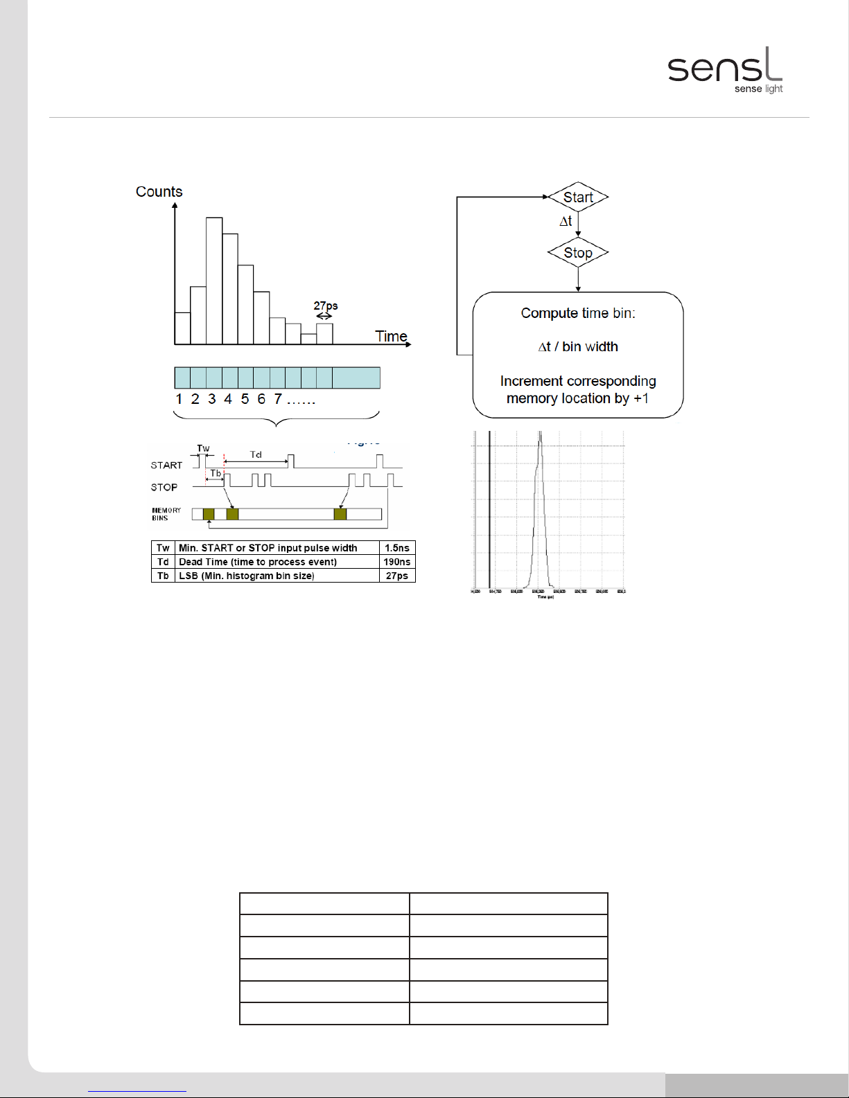
HISTOGRAM – SINGLE-STOP (“TCSPC” MODE)
Figure 5
Histogram modes use consecutive memory locations to store counts that represent successive timing values (Fig.5a).
These memory locations or “time bins” are incremented based on the result of a time measurement between a
START and the rst STOP received. In this single-stop mode, this is repeated to build up a histogram in memory
showing the distribution of rst events (STOPs) following a START input. This process is illustrated in Fig.5b and
Fig.5c, and an example GUI data plot is shown in Fig.5d. Data is saved to the PC in .CSV format. This mode is also
referred to as ‘TCSPC’ in the SIE, due to its application in Time Correlated Single Photon Counting.
Note: In this mode the START of each channel will be the event and the STOP will be a delayed version of the
LASER clock. On receipt of an event the timing value will be read and then the timing module will immediately be
reset. The reset will clear the channel ready for the next event. Each time-stamp from the timing module will be used
as an address to increment a memory location (time-bin). The resolution of the bins and the position of the curve in
memory will be dened by the highly exible Address Routing Module. The timing value, address counter and I/O
bits can all be routed to the memory address lines. This exibility allows many options, from a simple single curve to
multiple curves dened by the address counter and external control from the I/O port.
Min Time Bin Size: 27ps
Max Time Bin Size: 143ms
Max No. Time Bins: 4,194,304
Time Bin Depth: 65,536 or 4,294,967,296
Max Count Rate: 4.5Mcps
Max Image Size: 2048 x 4096
Fig.1c
a) b)
c) d)

SensL © 2011 15
USER MANUAL
HRM-TDC
SensL © 2011 15
> Hrm-tdc System Description > Histogram – Multi-stop (“multiscaler/counter”)
HISTOGRAM – MULTI-STOP (“MULTISCALER/COUNTER”)
Figure 6
In this mode, multiple STOP events following a single START event are recorded and their corresponding time bins in
the histogram incremented (Fig.6a). The following START input will reset the timer and the following STOP events will
be again recorded until another START is received. The process is illustrated in Fig.6b and Fig.6c. This is repeated to
build up a histogram in memory. Data is saved in .CSV format. The GUI will display a plot similar to that in Fig.5d. This
mode is also referred to as “Multiscaler/Counter” in the SIE. Please note that FIFO is not employed in this mode.
The Td (dead time) parameter is applicable in histogram multi-stop mode and limits the maximum frequency
achievable. Tm is the minimum time between any start and a subsequent stop.
Note: In this mode the START signal is a low frequency clock (less than 7 MHz). The STOP signals will be the events.
Unlike the single-stop mode, the 27ps timing module is not reset after the rst event. Due to the long clock period it
will be possible for the same channel to receive a number of events per clock cycle. Hence, in this mode the time-
bins will ll up to plot the occurrence of events over the period of the clock cycle. Each new START signal will reset
the 27ps timing module. This allows the system to build up a plot of all the events within the START pulse cycle.
Once again the exibility of the Address Routing Register provides a wide range of options from single to multiple
curves.
Min Time Bin Size: 27ps
Max Time Bin Size: 143ms
Max No. Time Bins: 4,194,304
Time Bin Depth: 65,536 or 4,294,967,296
Max Count Rate: 4.5Mcps
Max Image Size: 2048 x 4096
a) b)
c)
Fig.2b

SensL © 2011 16
USER MANUAL
HRM-TDC
SensL © 2011 16
> Hrm-tdc System Description > Fifo – Single-stop (“tcspc - With Macro-time”)
FIFO – SINGLE-STOP (“TCSPC - WITH MACRO-TIME”)
Figure 7
FIFO modes continually record the timing of events and save the results in consecutive locations in memory as
shown in Fig.7a. When the last location in memory is lled, if not commanded to STOP, the module continues to
record data starting at the beginning of memory again. The host PC, via the USB interface, keeps up in time with the
module, reading the data from memory to a le in the host computer. Hence the memory can be regarded as a very
large FIFO. Providing the host PC can keep up with the module, timing data can be recorded indenitely.
In this mode the module carries out the Single-STOP process as described previously and illustrated in Fig.7b and
Fig.7c. However, along with the timing of the Single-STOP event, a MACRO time (the time during the experiment that
this measurement is made) is also recorded. Both times are recorded in the FIFO. An example of the data recorded
is shown in Fig.5d. Data is saved in .CSV format. This mode is also referred to as ‘TCSPC (with Macro Time)’ in
the SIE, due to its application in Time Correlated Single Photon Counting.
Note: In this mode the START of each channel will be the event and the STOP will be a delayed version of the LASER
clock. On receipt of an event the timing value will be read and the MICRO time will be immediately reset. The reset
will clear the channel ready for the next event. All subsequent STOP pulses will be ignored until a new START pulse
arrives. Each time-stamp will be a 32-bit word giving the time since the last START (MICRO-time Tt1 or Tt2in Fig.7c)
and the value of a free running clock dening the time within the experiment (MACRO-time Tc). Due to the highly
exible Data Routing Module the resolution and number of bits for the micro time, macro time and channel ID bits is
selectable using the USB selection registers. When this process begins, 32-bit timing values will be inserted into the
shared memory. The memory will be congured as a large FIFO interfacing to the USB interface. Suitable handshake
signals are implemented allowing continuous transfer of time-tags from the FIFO to the PC via the USB port. With
counts of up to 4.5MHz this process can run indenitely without loss of data.
Fig.3c
Fig.3d
a) b)
c) d)

SensL © 2011 17
USER MANUAL
HRM-TDC
SensL © 2011 17
> Hrm-tdc System Description > Fifo – Multi-stop (“fo - Time Tagging”)
FIFO – MULTI-STOP (“FIFO - TIME TAGGING”)
Figure 8
In this mode the process is started with a single START pulse. The module will then ll the memory with time tags
dening the time of each STOP event with relation to the initial single START pulse. Any further START inputs will be
ignored. This mode is illustrated in Fig.8a and Fig.8c and is also referred to as ‘Time Tagging’. Data is saved as a
.CSV le. A typical data le is shown in Fig.8b.
There is a further ‘Re-Sync’ option within this mode that uses a 250KHz clock output from the module as the START
input. The clock continuously re-synchronizes the module to eliminate long term drift between channels. This is the
preferred method when it is required to compare the data from more than one channel.
Note: In this mode all STOP events will be time-stamped and saved to memory. Each time-tag will be comprised
of two 32-bit words. These two words will provide timing value, with a resolution of 27ps, and the channel ID.
The memory will be congured as a large FIFO interfacing to the USB interface. Suitable handshake signals are
implemented allowing continuous transfer of these time-tags from the FIFO to the PC via the USB port. Hence, in
this mode, continuous time tagging to the host PC can be achieved indenitely.
Fig.4b
Fig.4c
a)
b)
c)

SensL © 2011 18
USER MANUAL
HRM-TDC
SensL © 2011 18
> Sensl Integrated Environment (sie) > System Requirements
SensL Integrated Environment (SIE)
The SIE is a user interface for setting up and controlling the HRM-TDC module. While the interface provides an
extensive range of operating modes and measurement processes, including graphical presentation, it does not fully
cover all features available in the HRM-TDC module.
The SIE communicates with the module via a low level DLL. This DLL has been designed to provide a set of functions
that will allow full control of the HRM-TDC for all features. For complex experiments that require control beyond the
scope of the SIE, it is expected that the user will write their own real-time application utilizing the various function in
this DLL. For details of the DLL functions, see the Appendix in this document.
SYSTEM REQUIREMENTS
• Windows XP SP2 operating system
• 1 GByte of RAM
• At least one spare High Speed USB 2.0 port
• .NET Framework installed (included)
• JAVA runtime environment installed (included)
• Microsoft Visual C++ runtime components (included)
INSTALLATION
To install the TDC software and USB drivers, follow these steps:
• Go to www.sensl.com/support/sw/ and download both the ‘Release Note’ PDF and the ‘HRM-TDC
Software’ EXE les.
• Run the HRM-TDC_Install_XpXX.exe (where the XpXX is the revision number) le and follow the
instructions. After the GUI and DLLs are installed, you will be prompted to install QuickUSB drivers which
are necessary for communication with the TDC.
• Now power up the HRM-TDC module and connect the USB cable.
• The PC will recognize that new hardware has been added. Depending on the operating system the drivers
may be located automatically, or it may be necessary to select them manually by directing the PC to the
directory c:\Program Files\SensL\HRM-TDC\QuickUSB* where the necessary le will be located.
• The PC is ready to launch the TDC software. It can be found in the directory C:\Program Files\SensL\
HRM-TDC *
* This assumes you have used the default directory settings for your installation.

SensL © 2011 19
USER MANUAL
HRM-TDC
SensL © 2011 19
> Sensl Integrated Environment (sie) > Using The Sensl Integrated Environment (sie)
USING THE SENSL INTEGRATED ENVIRONMENT (SIE)
Main Page
When the SIE software is launched it will search the USB for available HRM-TDC modules and initialize them ready
for use. Once this has been carried out the main SIE page will appear as shown in Figure 9. A list of available devices
will be shown. To inspect and select the various operating modes available, right click on the module name and then
select the particular mode you require (see Fig. 9).
Figure 9 SIE Main Page screen
Module Information
This page displays the conguration information unique to this module. This information includes the module ID
number and the various measurement modes. This page also allows the user to upgrade the internal FPGA image.
To upgrade the FPGA image the user must rst click on the Update FPGA button. This will launch the Update Wizard
as shown in Figure 10. Use the Browse button to nd the RPD le for upgrading. Finally click the Update Device
button to start the upgrade.
WARNING:
USB communication must be maintained during this process. Do NOT disconnect the USB cable during the update.

SensL © 2011 20
USER MANUAL
HRM-TDC
SensL © 2011 20
> Sensl Integrated Environment (sie) > Using The Sensl Integrated Environment (sie)
Updating the FPGA should only be carried out if you are instructed to do so by SensL. This procedure requires a
valid RPD le as provided by SensL.
Failure to carry out this process correctly may render the module inoperable resulting in the need to return it to SensL
for reconguration.
Figure 10 SIE Module Information screen
“HISTOGRAM –TCSPC” (Histogram Single-stop)
When this page is launched the top half will display a graph page. Left click on this graph to reveal the conguration
settings. The size of the conguration and graph area can be adjusted by dragging the partition to suite. Figure 11
show this page with the partition adjusted to reveal the entire conguration controls.
Programmable Clock Output
The Programmable Clock Output is made available for all modes and is used to set the frequency and duty cycle of
the internal programmable clock. This clock is available at an SMA output for test purposes. This clock is provided
for testing and diagnostics. The clock will exhibit a level of jitter that would not be suitable for accurate measurements
as part of an experiment.
External Clock Period
This should be set to the period of the external LASER clock.
Table of contents
Popular Control Unit manuals by other brands


Interacoustics
Interacoustics Callisto AC440 Instructions for use

Pilz
Pilz PNOZ m0p operating instructions

Emerson
Emerson PACSystems IC695ACC302 Important product information

GEM
GEM R470 Tugela operating instructions

TrakPower
TrakPower V-Balance manual

Asco
Asco 8317 Series Installation & maintenance instructions