Sensoray 2464 User manual
SENSORAY | p. 503.684.8005 | email:info@SENSORAY.com | www.SENSORAY.com
7313 S Tech Center Drive | Portland, OR 97203
Multistandard Video Capture Device
s
Models 2464/3364
Hardware Manual
Ver. 1.0.0 | July 2017

2
Table of Contents
Limited warranty ....................................................................................................... 3
Introduction .............................................................................................................. 4
System Requirements ................................................................................................ 5
Block Diagrams ......................................................................................................... 6
Connectors ...............................................................................................................
Specifications ............................................................................................................ 9
SDI option ............................................................................................................. 9
DVI option .......................................................................................................... 10
Recommended adaptors .......................................................................................... 11
Analog Audio Accessory Board ................................................................................. 12
Software................................................................................................................. 13
Firmware updates ................................................................................................... 14
Model 3364 firmware update ................................................................................ 14
Model 2464 firmware update ................................................................................ 14
Revision history ...................................................................................................... 16

3
Limited warranty
Sensoray Company, Incorporated (Sensoray) warrants the hardware to be free from defects
in material and workmanship and perform to applicable published Sensoray specifications
for two years from the date of shipment to purchaser. Sensoray will, at its option, repair or
replace equipment that pro es to be defecti e during the warranty period. This warranty
includes parts and labor.
The warranty pro ided herein does not co er equipment subjected to abuse, misuse,
accident, alteration, neglect, or unauthorized repair or installation. Sensoray shall ha e the
right of final determination as to the existence and cause of defect.
As for items repaired or replaced under warranty, the warranty shall continue in effect for
the remainder of the original warranty period, or for ninety days following date of shipment
by Sensoray of the repaired or replaced part, whiche er period is longer.
A Return Material Authorization (RMA) number must be obtained from the factory and
clearly marked on the outside of the package before any equipment will be accepted for
warranty work. Sensoray will pay the shipping costs of returning to the owner parts that are
co ered by warranty. A restocking charge of 25% of the product purchase price will be
charged for returning a product to stock.
Sensoray belie es that the information in this manual is accurate. The document has been
carefully re iewed for technical accuracy. In the e ent that technical or typographical errors
exist, Sensoray reser es the right to make changes to subsequent editions of this document
without prior notice to holders of this edition. The reader should consult Sensoray if errors
are suspected. In no e ent shall Sensoray be liable for any damages arising out of or related
to this document or the information contained in it.
E
XCEPT AS SPECIFIED HEREIN, SENSORAY MAKES NO WARRANTIES, EXPRESS OR
IMPLIED, AND SPECIFICALLY DISCLAIMS ANY WARRANTY OF MERCHANTABILITY OR
FITNESS FOR A PARTICULAR PURPOSE. CUSTOMER’S RIGHT TO RECOVER DAMAGES
CAUSED BY FAULT OR NEGLIGENCE ON THE PART OF SENSORAY SHALL BE LIMITED
TO THE AMOUNT THERETOFORE PAID BY THE CUSTOMER. SENSORAY WILL NOT BE
LIABLE FOR DAMAGES RESULTING FROM LOSS OF DATA, PROFITS, USE OF PRODUCTS,
OR INCIDENTAL OR CONSEQUENTIAL DAMAGES, EVEN IF ADVISED OF THE
POSSIBILITY THEREOF.
Third party brands, names and trademarks are the property of their respecti e owners.

4
Introduction
Models 2464/3364 capture ideo from an SDI, DVI, VGA or component source. Model
2464 has Ethernet interface, whereas model 3364 has a USB 3.0 interface. Model 3364
captures uncompressed HD/SD ideo in resolutions up to 1080p60, and will o erlay
and compress resolutions up to 1080p30. It can simultaneously send both compressed
and uncompressed ideo to the host computer. Model 2464 captures compressed ideo
and sends it o er the Ethernet in se eral different formats.
Analog audio can be captured from a microphone or line source using an optional
3364TA accessory board. Audio may be sent uncompressed, or it may be compressed
and multiplexed into a transport stream along with compressed ideo, or both
simultaneously.
The 3364 is a UVC (USB Video Class) de ice, which means it does not require a de ice-
specific dri er and can be easily controlled using popular ideo APIs such as
DirectShow and Video4Linux. Sensoray pro ides Software De elopment Kits (SDKs)
for se eral operating systems to accelerate application de elopment. Our fully
functional demo program illustrates model 3364's capabilities and ser es as an excellent
starting point for custom designs.
The ideo processor implements efficient H.264 ideo compression, producing output
data formatted as either MPEG transport stream (MPEG-TS) or in MP4 or AVI file
formats. Audio compression is performed using AAC-LC. The stream multiplexer
employs high precision hardware timestamps to ensure perfect audio- ideo sync on
players. Snapshot capture is also supported, with MJPEG compression a ailable for
both snapshots and AVI streams.
For ideo resolutions up to 1080p30, the 3364 can pass through unaltered or downsized
ideo while adding Unicode text and graphical o erlays (which may uploaded in real
time ia USB). Audio pass-through is a ailable with an optional, attached 3364TA
board. Embedded audio can also be extracted from SDI signal.
The units ha e one input and one output ideo connector. Depending on the model
number, both connectors are either DVI or SDI. DVI models can capture ideo from a
DVI, VGA or component ideo source (with appropriate adaptors), and output DVI.
SDI models accept SDI signals per SMPTE 259M(C), SMPTE 292M, and SMPTE 424M.
Models 2464 and 3364 are a ailable as a bare boards or in a robust metal enclosure.

5
System Requirements
For model 3364 a computer with nati e USB 3.0 port is recommended. PCIe USB 3.0
extension cards may not pro ide bandwidth sufficient for 1080p60 ideo.
Supported operating systems:
Windows 7, 8, 10;
Linux 2.6, 3.x, 4.x.
Model 2464 requires a 100Base-TX Ethernet connection. Power-o er-Ethernet (POE) is
supported, as well as an external 5V power supply. The default Ethernet address is
192.168.24.64, net mask 255.255.0.0.

6
Block Diagrams
Fig.1. Model 3364 block diagram.
7
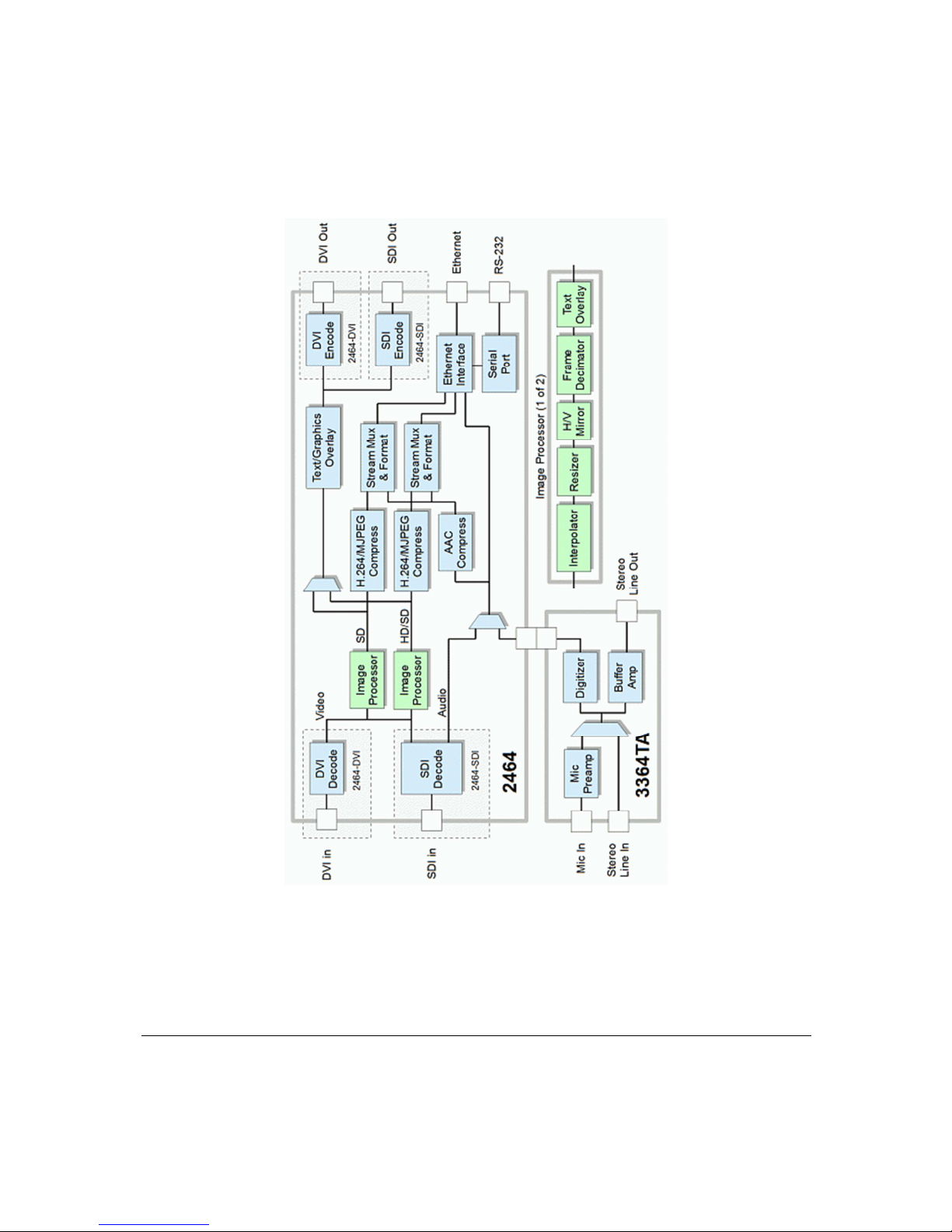
Fig.2. Model 2464 block diagram.

8
Connectors
Input/output connectors for SDI and DVI ersions, with and without optional audio
board (3364TA).

9
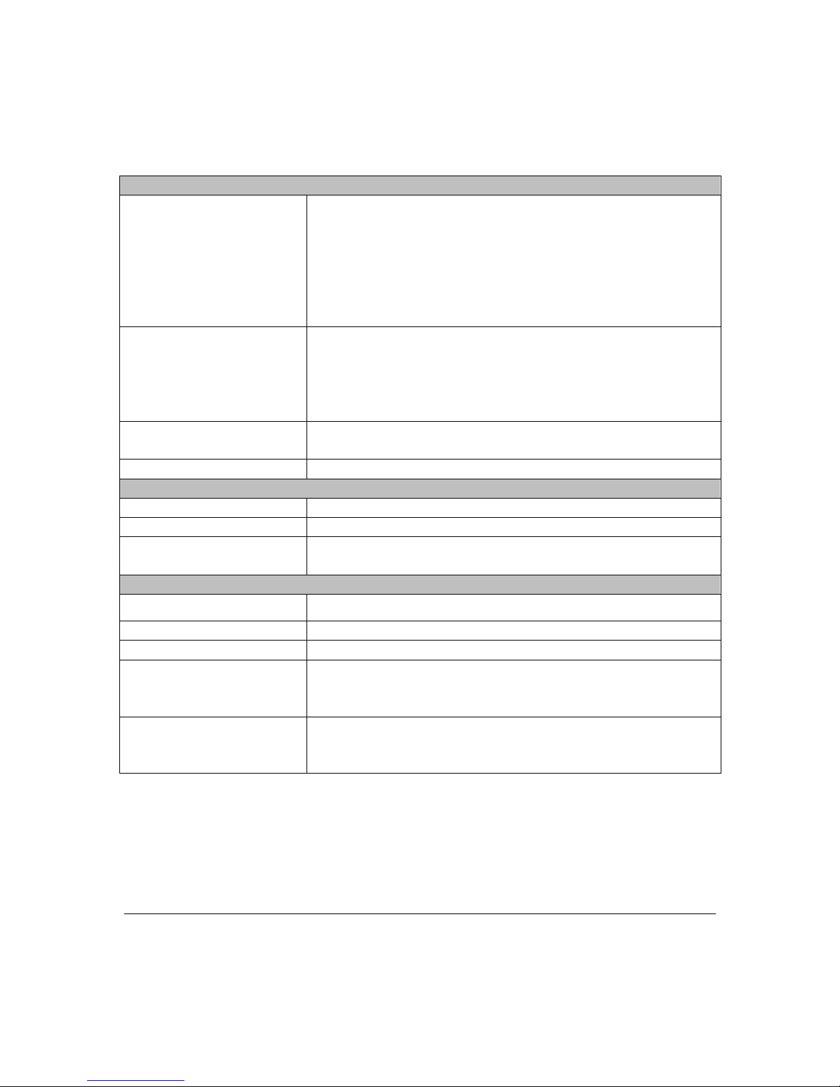
Specifications
SDI option
Video Input/Output
Data rates 270 Mbps, 1.483 Gbps, 1.485 Gbps, 2.97 Gbps
Standards
SMPTE 259M(C), SMPTE 292M, SMPTE
424M
Maximum
resolution/frame rate
1920x1080p60 (uncompressed, 3364 only)
1920x1080p30 (compressed)
Connectors
BNC, 75 Ohm
Output ideo streams
H.264
High Profile @ Le el 3 (MP4, AVI, transport stream)
JPEG Single snapshots, AVI
Raw (uncompressed) UYVY (3364 only, full resolution at full frame rate a ailable
with USB 3.0
-
capable hosts only)
Electrical, mechanical and en ironmental
Dimensions 71x100 mm (PCB outline, does not include connectors)
Mass 40 g (without an enclosure)
Operating temperature 0º to 70º C
Interface
3364
2464
USB 3.0, USB 3.0 micro B connector
100 Base-TX Ethernet, RJ-45
Power
3364
2464
USB bus powered
5 V power supply or POE
10
DVI option
Video Input/Output
Input resolutions/frame
rates (DVI, VGA,
component, composite)
720x480i60
720x576i50
1280x720 at p30, p25, p60, p50
1920x1080 at i60, i50, p30, p25, p24
1920x1200p30
1680x1050p30
1600x1200p30, 1600x900p30
Output
resolutions/frame rates
(DVI)
720x480p59.94
720x576p50
1280x720p30, p50, p60
1920x1080i50, i60
1920x1080p24, p25, p30
Maximum
resolution/frame rate
1920x1080p60 (uncompressed, 3364 only)
1920x1080p30 (compressed)
Connectors
BNC, 75 Ohm
Output ideo streams
H.264 High Profile @ Le el 3 (MP4, AVI, transport stream)
JPEG
Single
snapshots, AVI
Raw (uncompressed) UYVY (3364 only, full resolution at full frame rate a ailable
with USB 3.0
-
capable hosts only)
Electrical, mechanical and en ironmental
Dimensions 71x100 mm (PCB outline, does not include connectors)
Mass
40 g
(without an enclosure)
Operating temperature 0º to 70º C
Interface
3364
2464
USB 3.0, USB 3.0 micro B connector
100 Base-TX Ethernet, RJ-45
Power
3364
2464
USB bus powered
5 V power supply or POE
11
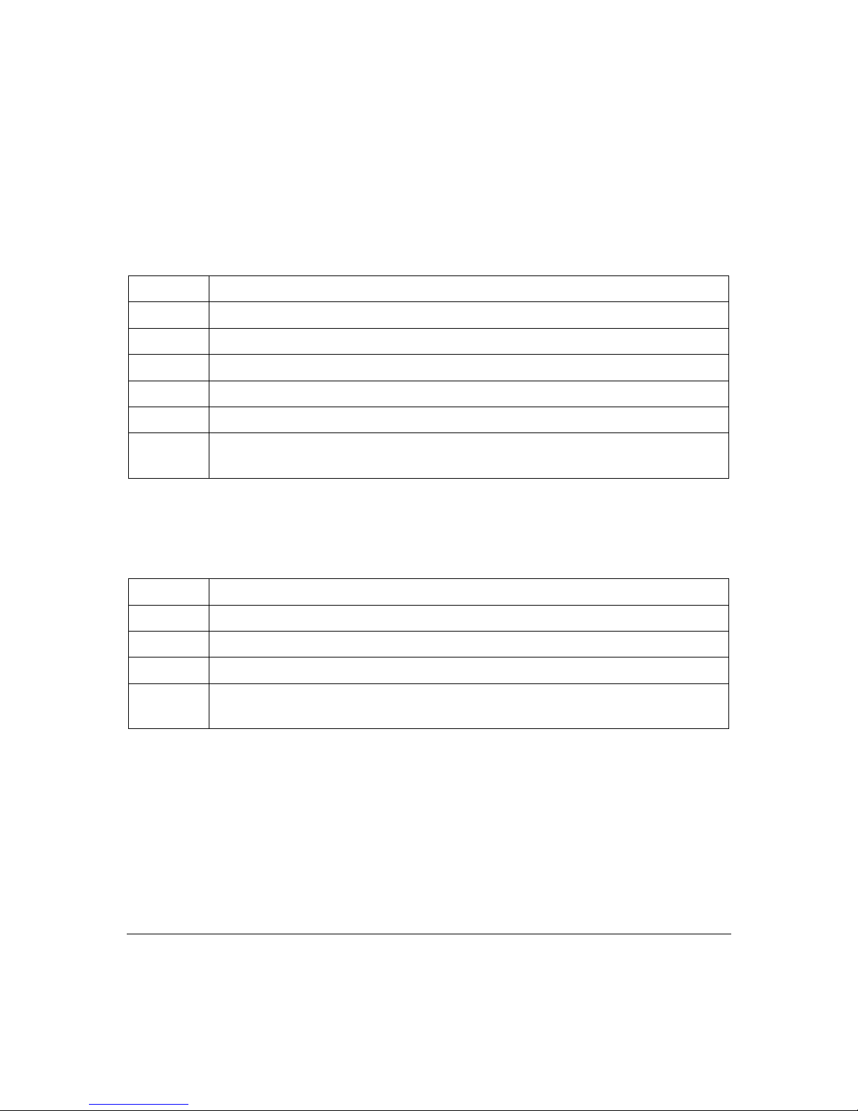
Recommended adaptors
DVI to VGA: Dynex DX-D1114, or similar. The following pins of the DVI connector
carry VGA signals:
Pin Signal
25 Red
26 Green
27 Blue
28
Hsync
8
Vsync
3,11,15,19,
22,29,30,32
Ground
DVI to component: Monoprice DVI-I-3-RCA adaptor/cable, or similar. The following
pins of the DVI connector carry component signals:
Pin Signal
25 Red
26
Green
27
Blue
3,11,15,19,
22,29,30,32
Ground
DVI to composite: composite input is taken from the RED channel signal (pin 25 of the
DVI connector; ground is pins 29, 30).

12
Analog Audio Accessory Board
Analog audio can be captured and played back (along with the ideo) with the help of
an accessory board, model 3364TA. It is a ailable separately, or as part of an enclosed
ersion, DVI or SDI.
Audio embedded in the SDI signal can be extracted as well.
13
Software
Software (Windows and Linux)
Dri er
UVC ideo
SDK Library wrappers around the DirectShow
(Windows) or V4L2 (Linux) APIs

14
irmware updates
Both models 2464 and 3364 feature flash memory that contains the firmware used to
operate the hardware on the de ice. This firmware can updated in the field to fix
problems or add new features.
Model 3364 firmware update
Firmware can be updated by selecting an Update option in the demo application or by
calling the corresponding SDK function. Upon those actions the de ice reconnects as a
USB mass storage de ice with the name Update2263. (If the AutoPlay menu appears,
choose the “Open folder to iew files option”). In this mode, a new firmware file may
be copied to the Update2263 folder. While the file is being written to the flash memory,
the red LED blinks. Do not uplug the de ice while the red LED is blinking. After the
update is complete, the Update2263 folder is closed, and the 3364 reconnects as a UVC
de ice. To cancel the update mode without updating firmware, right click the
Update2263 remo able de ice in Computer and click Eject. In the unlikely e ent that a
firmware update was interrupted in a way that pre ents the de ice from operating, an
original firmware mode (Safe Boot mode) is a ailable. To enter Safe Boot mode, press
and hold the button through the hole below the indicator LEDs while connecting the
USB cable. The red LED will illuminate, indicating the original firmware has entered
firmware update mode and a new firmware image may be applied. After the procedure
is complete, in order to switch to the newly updated firmware, the power needs to be
cycled by disconnecting and reconnecting the USB cable.
Model 2464 firmware update
The firmware update is initiated using web interface. That requires a computer, located
on the same network as the 2464. Using any browser connect to the 2464, and select
Firmware Update, which will bring up the window that displays the ersions of the
de ice's firmware components and the serial number. To update the firmware, choose
the file (s2464.fw pro ided by Sensoray) and press Submit. The firmware update should
take about 30 seconds to complete. Do not unplug the de ice while the firmware update
is in process. If a firmware update is interrupted, the de ice will attempt to load from a
backup firmware image. During the update the red LED flashes and update status is
displayed in the Firmware Status field of the web page. If the update has completed
successfully a message “Firmware result: ok” is displayed in a pop-up window. All
de ice settings are preser ed across the firmware update. To reset the all parameters on

15
the de ice, click the Reset Parameters button. That will reset the network settings as
well, but the change to those will take effect only after the power is cycled. This allows
setting an IP address different from the default (192.168.24.64) e en after parameters
reset, if necessary.

16
Revision history
Version Notes
1.0.0, July 2017 Initial release.
This manual suits for next models
1
Table of contents
Other Sensoray TV Tuner manuals


