A2B Electronics MyM micro master 3T User manual

User manual MyM DVB-3T , rev B eng Page 1
English
MyM
3T
User Manual
•
NICAM or A2 stereo
•12-volt ower su ly
•Low ower consum tion
•
Com act unit with
2
DVB
-
T t
uners
•MPEG-2 and MPEG-4 com liant
•3 analogue modulators
•Two CI for decry tion or multidecry tion

User manual MyM DVB-3T , rev B eng Page 2
1Contents
1
Contents
............................................................................................................................... 2
2 Un acking Your MyM
.............................................................................................................. 2
3 Introduction
.......................................................................................................................... 3
4 Information about digital terrestrial television
....................................................................... 3
5
Installation Part one
............................................................................................................. 4
6
Connectors and buttons
......................................................................................................... 4
7
Installation Part two
............................................................................................................. 5
7.1 Connection to one TV ............................................................................................................................... 5
7.2 Connection to a Cable network.............................................................................................................. 5
7.3 Automatic installation and channel search.......................................................................................... 6
7.4 TV channel search .................................................................................................................................... 6
8
Menu settings
....................................................................................................................... 7
8.1 Basic settings............................................................................................................................................. 7
8.1.1. Information................................................................................................................................. 7
8.1.2 Choosing channels (Channel 1, 2,3) ......................................................................................... 7
8.1.3 Channel search ........................................................................................................................... 7
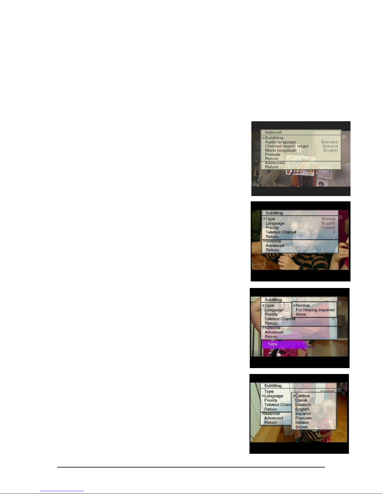
8.1.4 National ............................................................................................................................................. 8
8.1.5 National – Subtitling .................................................................................................................. 8
8.1.6 National – Au io language .............................................................................................................. 9
8.1.7 National – Menu language............................................................................................................... 9
8.2 Advanced settings...................................................................................................................................... 9
8.2.1 Aspect ratio (Picture format) ........................................................................................................ 9
8.2.2 Output channels ............................................................................................................................. 10
8.2.3 Quality ............................................................................................................................................. 10
8.2.5 Channel in icator........................................................................................................................... 11
8.2.6 Output au io type.......................................................................................................................... 11
8.2.6.1 TV System for au io .............................................................................................................. 11
8.2.7 Loopthrough.................................................................................................................................... 12
8.2.8 CI 1 an CI 2 .................................................................................................................................... 12
9
Multi le installation
............................................................................................................ 12
9.1 Installation of multi le MyM’s .............................................................................................................. 12
9.2 Connecting a Set-To -Box with the MyM ............................................................................................ 13
10
Su ort and trouble-shooting
.............................................................................................. 14
10.1 Trouble-shooting................................................................................................................................... 14
11
Technical s ecification
....................................................................................................... 15
12
Declaration of Conformity
................................................................................................... 16
2 Unpacking Your MyM
When un acking the carton following items should be included.
1. MyM
2. Power ada tor
3. User Manual

User manual MyM DVB-3T , rev B eng Page 3
3 Introduction
Thank you for urchasing the MyM Micro Master, a quality roduct develo ed and
manufactured by A2B Electronics.
The MyM is a unique solution that allows you to watch digital television on all your
TV sets. The MyM receives all terrestrial digital rograms, and re-transmits 3
rograms simultaneously to all your TVs.
This User Manual describes how to install and connect your MyM quickly and easily .
In the unlikely event that you ex erience any difficulties lease refer to Cha ter
10, Su ort and Trouble Shooting.
4 Information about digital terrestrial television
Today there are digital terrestrial channels available, both free to air and
encry ted channels.
The terrestrial digital channels are transmitted in muxes. A mux (or multi lex) is a
ackage of channels that are transmitted on the same frequency. Each mux
normally contains between 4 and 7 channels. Frequently a mux will contain both
free to air and ay TV channels.
The MyM receives transmissions from 2 muxes, and re-transmits 3 of the digital
channels in analogue with Nicam or A2 stereo to all connected receivers (TV-sets,
VCR’s etc.) in the cable TV network. There is also a loo through of the digital
muxes, which makes it ossible to connect a Set To Box (STB) after the MyM.

User manual MyM DVB-3T , rev B eng Page 4
5Installation art one
The MyM should be mounted correctly to ensure excellent erformance over a long
eriod of time.
Please note that it is im ortant to mount the MyM vertically for correct airflow.
Attach the MyM to a suitable surface using the holes on the back side. We
recommend that you use 2 screws (3.5mm x 20 mm). There is also a wall mount
late that can be locked for rotection of the CAM’s.
Install the MyM for easiest connection of the cables. If the MyM is installed in the
attic, mount it close to the aerial. Also, make sure you have a 230V AC ower
outlet. For more information about how to install the MyM lease refer to Cha ter
7 Installation.
6Connectors and buttons
Connectors and buttons
1. Aerial in
2. Antenna loo through
3. TV out
4. DC- ower (12 V)
5. RJ-45 for u dates
1)
6. LCD o eration indicator
7. Arrow u for menu navigation
8. Arrow down for menu navigation
9. OK button for showing menus and
for menu choice
1) See www.a2b.se for information about new software.
1
2
3
4
5
6
7
8
9

User manual MyM DVB-3T , rev B eng Page 5
7Installation art two
7.1 Connection to one TV
If you only want to connect one TV, or one TV combined with a VCR / PVR, the
most straight-forward installation is to mount the MyM on the wall close to the TV.
1. Connect the aerial cable to the aerial
in ut on the MyM
2Connect the one end of a RF cable to
the RF out ut on the MyM, and connect
the other end to the aerial in socket on
your TV.
3Connect the ower ada tor (only use
the ada tor delivered with the MyM).
4The MyM will now start an automatic
channel search. When the channel
search is finished the LED on the MyM
will turn green and you will need to do
a channel search on your TV set. See
Cha ter 7.3 Automatic installation and
channel search, for more information.
Note! Do not use any other the power a aptor than the original one with the MyM.
7.2 Connection to a Cable network
The MyM should be connected close to the aerial, before the signals are s lit to the
cable network.
If there is an am lifier connected to the
s litter you should first try to install
the MyM without the am lifier, because
the MyM has an embedded am lifier.
If there are very long cables in the
cable network, an am lifier can be
needed and should then be connected
after the MyM.
1
2
3
S litter
M
yM
TV TV
TV TV

User manual MyM DVB-3T , rev B eng Page 6
7.3 Automatic installation and channel search
The MyM will automatically start a channel search when it is connected to a TV
aerial and the ower ada tor is connected. The MyM will search for the strongest
transmissions, and after that it will start transmitting three channels according to
the table below:
Channel Frequency
S11 231,25 MHz
S13 245,25 MHz
S15 259,25 MHz
The channel search takes about 60 seconds. When the channel search is com lete,
and the MyM have found FTA channels, the LED on the MyM switches to green.
NOTE! In normal operation the LED flashes green.
7.4 TV channel search
Once the channel search on the MyM is com lete you
will need to do a channel search on all TV’s and VCR’s
in the cable network. Many TV sets have an automatic
channel search facility - for more information lease
refer to the TV and VCR User Manuals. Channels
coming from the MyM will be highlighted by a text box
with “MyM 1” in the u er right corner. This text box
will disa ear automatically after 8 hours. You can
also remove the text box manually via the menu system of the MyM, see Cha ter 8
Menu settings, for more information.
If you need hel to install your MyM, lease contact your local dealer/installer. You
can also visit our web site for more information: www.a2b.se
LED

User manual MyM DVB-3T , rev B eng Page 7
8Menu settings
The MyM has a menu system for changing
settings and functionality. The menus are shown
on the TV screen. Press the OK button on the MyM
(see Cha ter 6 Connectors and buttons) to dis lay
the menus. The icture to the right shows the
main menu. Use the arrow u and arrow down
buttons on the MyM to navigate the menus. Exit
the menu by moving the indicator to “Return” and
then ress the OK button on the MyM.
8.1 Basic settings
In the basic settings you can find information about your MyM, choose what
rograms are transmitted by the MyM, and start a new channel search.
8.1.1. Information
The information box dis lays the hardware
version and the software version of your MyM.
It also dis lays the serial number of your
MyM.
8.1.2 Choosing channels Channel 1, 2,3)
This menu is used for selecting which digital
television channels are transmitted by the MyM on
Channels 1, 2 and 3.
•Move the indicator (using the arrow buttons
on the MyM) to the Channel you want to
change.
•Press the OK button on the MyM to show all
the digital television channels.
•Select the digital television channel and
ress the OK button again.
8.1.3 Channel search
The first time the MyM is installed it will do an
automatic channel search to tune in all available
digital channels. This menu can be used for
starting a new channel search, for exam le if you
take the MyM to a new location.

User manual MyM DVB-3T , rev B eng Page 8
Connect the TV aerial before starting the channel search. To follow the channel
search rocess tune a TV to channel S11 (231,25 MHz). During the channel search
all the signals that come from the aerial are shown at the bottom of the screen by
individual channels (frequencies) and signal strength. The digital muxes have green
indicators. Other signals have blue indicators. Please refer to Cha ter 8.2 Advanced
Installation, for more information about signal quality and how to how to adjust
the TV aerial.
All the channels that are received and identified are dis layed in the background.
8.1.4 National
This menu is used to change the country settings. You can
choose your references for subtitling, audio language,
channel search, menu language and resets.
8.1.5 National – Subtitling
Use this menu to set your references for subtitling. It is
ossible to set the ty e of subtitling, choose the subtitle
language and select between DVB-T or teletext subtitling,
and set the teletext character set. This menu can also be
used to switch subtitling off (None).
8.1.5.1 Type
Use this menu to choose between normal subtitling or
s ecial subtitling for the hearing im aired. This offers
enlarged subtitles and colour coded text. Alternatively all
the subtitling can be switched off. The MyM is reset to
“Normal”.
8.1.5.2 Language
In this menu you select what language that should be used
for subtitling.
NOTE! There are more choices than you can see in the
win ow. Scroll up or own to see all choices.

User manual MyM DVB-3T , rev B eng Page 9
8.1.5.3 Priority
Subtitling can be transmitted in different formats; via
“teletext subtitling or “DVB subtitling”. The format is
automatically selected by the MyM. Sometimes both
formats are transmitted and the MyM then automatically
chooses the format according to the riority set here.
8.1.6 National – Audio language
This menu is used to set your reference for audio
language, when a TV rogram is broadcast in more than 1
language.
8.1.7 National – Menu language
This menu is used to set your reference for the language
used in all the Menus in the MyM.
8.2 Advanced settings
In the advanced settings menu you will find settings for
icture format, out ut channels, signal quality, Auto MUX
search, Channel indicator, Out ut audio ty e and
Loo through.
8.2.1 Aspect ratio Picture format)
The icture format can be set to 4:3 or 16:9 (Widescreen).
If the main TV is 4:3 choose 4:3 to watch 4:3 rograms in
full screen and widescreen rogrammes (16:9) in the
letterbox format where the full width of the icture is
shown and the to and bottom of the icture are black.
Choose 16:9 if the main TV is widescreen to watch 16:9
rogrammes in full screen.

User manual MyM DVB-3T , rev B eng Page 10
8.2.2 Output channels
Use this menu to choose the out ut frequencies for the
MyM. After automatic installation you will find the reset
channels on VHF out ut at channels S11, S13 and S15
res ectively. This menu allows you to choose between
VHF (S10 to S41) or UHF (E21 to E69) as out ut channels.
8.2.3 Quality
This menu is used to test the signal quality and the aerial
rece tion quality. It may be necessary to adjust or
u grade the TV aerial to ensure good icture and sound on
all channels. For more information see Cha ter 8.2.3.1
Rece tion.
The MyM has an inbuilt s ectrum analyser to hel o timise
the aerial installation. For more information see Cha ter
8.2.3.2 Antenna Quality.
8.2.3.1 Reception
Use this menu to measure the rece tion quality of each
channel. If these are not o timal it is ossible that the
icture and sound quality will deteriorate in oor
rece tion conditions and it may be necessary to adjust the
aerial. The information refers to the 2 installed muxes for
the 3 channels.
The menu shows the channels numbers and frequencies of
the 2 installed muxes. Good rece tion quality requires a
strong incoming signal. For more information on the o timal signal strength see
Cha ter 8.2.3.2 Antenna Signal. It may be necessary to adjust the aerial for
o timal signal strength. The signal quality C/N (Carrier to Noise) value is a
measurement of the relationshi between the aerial signal and disturbance in the
channel. This should be higher than 20 dB. The BER (Bit Error Rate) measures the
number of ratio of the number of faulty bits received to the total number of bits
received. The BER should be as low as ossible and less than 2.00E-4 (2*10
-4
) to
ensure good quality icture and sound.

User manual MyM DVB-3T , rev B eng Page 11
If all the arameters for the incoming signal are good but there are still roblems
with the icture or sound quality it is likely that there is a roblem with the cable
that connects the TV / VCR to the MyM.
8.2.3.2 Antenna quality
The MyM has an inbuilt s ectrum analyser. This
shows the level of the incoming signals on the VHF
and UHF band (47 to 862 MHz). The icture to the
right shows the signal level of the incoming
channels. The two chosen muxes for the installed
channels are green. The recommended level for the
incoming channels is between 35 dBµV and 75 dBµV
(between the 2 red horizontal lines).
Check that the green columns are between the 2 red horizontal lines. If not it may
be necessary to adjust or u grade the TV aerial.
8.2.5 Channel indicator
The MyM Channel indicator can be switched between
on and off. When the channel indicator is on, a text
box with ”MyM 1” will be shown in the u er right
corner of the icture. After installation the channel
indicator is automatically switched on for 8 hours to
make it easier to do a channel search on the TV.
During normal o eration, the channel indicator is off.
8.2.6 Output audio type
In this menu it’s ossible to choose between different
Audio ty es like Nicam, A2 or A2*.
8.2.6.1 TV System for audio
Here you select which TV system
that will be selected for the sound.
Most common in Western Euro e is
B/G.

User manual MyM DVB-3T , rev B eng Page 12
8.2.7 Loopthrough
In this menu you can choose whether you want the
antenna signals to ass through the MyM. If you select
mode "On" then the FM, VHF and UHF band to be
im orted and thus these signals will be available in the
antenna network after the MyM. A ro riate to ut in
the "On" mode if the MyM is connected to a network with
digital TV boxes or TV sets with built-in digital receiver.
8.2.8 CI 1 and CI 2
The CI 1 and CI 2 menus gives you the ossibility to get
information about CAM and Smartcard. CAM Interface 1
(CI 1) is used for decry tion of services that is selected
for Out ut channel 1 and 2. CAM Interface 2 (CI 2) is used
for decry tion of one service for Out ut channel 3.
9Multiple installation
9.1 Installation of multiple MyM’s
You can link MyM’s to view more rograms on all your TVs. The maximum number
of MyM’s you can cascade is 4. The limit is set by the S/N value that has to be
above a certain level to give a good icture quality.
To link 2 MyM’s:
•Install the first MyM
•Do a channel search on
the TV
•Change out ut channels in the
MyM no 1.
•Link the MyMs with a cable from
“Ant 2” connection on the first
MyM to “Ant 1” connection on the
second MyM. Connect the out ut
of the two MyM’s with a combiner
(see icture).
•Power u and install the second MyM
•Do another channel search on the TV and find the MyM channel one for each
MyM. Please remember that you can’t use neighboring out ut channels, not
even if they are on different MyM’s.
M
yM #1
MyM #2

User manual MyM DVB-3T , rev B eng Page 13
9.2 Connecting a Set-Top-Box with
the MyM
The MyM has a loo -through facility that
makes it ossible to connect digital Set
To Boxes (STB) after the MyM for
households in the Cable network that
want to watch other channels than those
su lied with the MyM.
TV TV
M
yM
STB

User manual MyM DVB-3T , rev B eng Page 14
10 Support and trouble-shooting
If you need more hel with installation, lease contact your local dealer. You can
also find more information on our web site: www.a2b.se
10.1 Trouble-shooting
Consider purchasing a
Set Top Box for Pay
TV programs
The MyM only
receives free-to-air
digital terrestrial
programs
No Pay-TV
reception
Consider purchasing a
TV with Nicam/A2
stereo sound
No stereo decoder
in your TV
Does your TV set
have stereo? Is stereo
selected?
No stereo sound
Install the Multibox
vertically according to
the instructions
Overheating due to
faulty installation
Is the MyM lying
down?
Flickering sound
and blockings in
the picture
Adjust or replace the
aerial for a better signal
Low signal level
from the aerial
Flickering sound
and blockings in
the picture
Adjust or replace the
aerial for a better signal
Low signal level
from the aerial
Is the picture OK?
Flickering sound
Go to ”Return” with the
arrow buttons, then
press the [OK] button
on the Multibox
Menu not switched
off
The TV picture
shows a menu
Do a channel search
on the TV
Channel search
not done on TV
Indicator LED green
No sound or
picture
Adjust or replace the
aerial for a better signal
No or poor signal
from the aerial
Indicator LED red
No sound or
picture
Action
Probable cause
Analysis
Error
Remove the aerial
signal amplifier
The input level to
the MyM or to the
TV is too high
Are you using an
aerial signal amplifier?
Flickering sound
and/or blockings
in the picture

User manual MyM DVB-3T , rev B eng Page 15
11 Technical specification
2 x DVB-T TERRESTRIAL RECEIVER
Frequency range 47-862 MHz
Connector Ty e F female, 75 ohm
In ut level range Nom. 35 – 75 dBµV
Bandwidth 7/8 MHz
Number of tuners 2
3 x M EG DECODER – VIDEO - AUDIO
Video standard MPEG2 MP@ML, MPEG4
H.264 AVC
Audio standard AAC HE or MPEG1
Layer II AC-3 (o tion)
As ect ratio Letterbox, Anamor hic,
Teletext Insertion in VBI
Subtitling Teletext or DVB subtitling
3 x MODULATOR
Modulation standard PAL B/G, I, D/K (DSB)
Audio FM-mono, NICAM stereo
A2 or A2*
Out ut channels 160 to 862 MHz
Pre-selected:
S11, S13, S15
Out ut level ty . 80 dBuV, fixed
Loo -through 47 - 862 MHz
Selectable On/Off
Built-in aerial am lifier 5 dB
RF out ut connector Ty e F female, 75 ohm
DECRY TION
Decry tion interface Common Interface
(PMCIA 5VDC)
Decry tion ty e Single or Multidecry tion CAM’s su orted
OTHERS
AC Power su ly 230 VAC ty (94-264 VAC)
AC Power consum tion Ty . 18 W
DC out ut ower 12 VDC +/- 10%
DC ower consum tion Ty . 15 W
Size 301x215x53mm (excl. connectors)
Weight a rox. 900 g
O erating tem erature -20 to +45°C
We reserve the right to technical changes without prior notice.

User manual MyM DVB-3T , rev B eng Page 16
12 Declaration of Conformity
Declaration of Conformity
EC Directives
MyM 3T complies to the relevant parts of the directives and standards below.
Directives
•Electro magnetic compatibility directive (EMC) 89/339/EEC
•Low voltage directive (LVD) 73/23/EEC
•CE-marking directive 93/98/EEC
Standards
EMC: Emission - EN61000-6-3:2001
Immunity - EN61000-6-1:2001
Safety : EN 60 950-1:2001
Further information on
www.
a2b
.se
6553
0
0
-
01
B
Table of contents