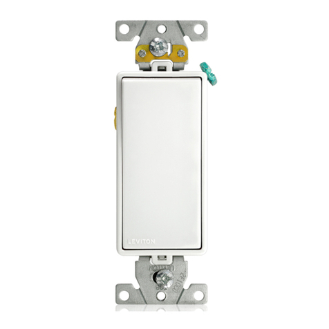
SENSORWORX SWX-801 Series Installation instructions

LOW VOLTAGE
MOMENTARY SWITCH &
0-10V DIMMER
INSTALLATION & OPERATION INSTRUCTIONS
OVERVIEW
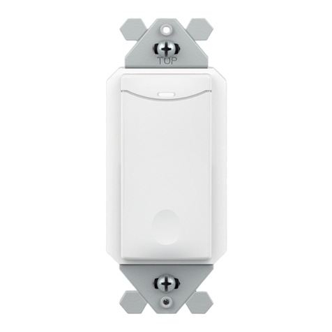
The SENSORWORX low voltage decorator wall station functions as a momentary switch with a pulse length
of 250 msec. Typically, it is utilized along with any SENSORWORX power pack with the auxiliary switch input
option (e.g. model SWX-900-AX). Using a four-conductor low voltage wire (typically 18 AWG), low voltage power,
common, and relay status is wired from the power pack to the switch. The switch output is then wired back to the
power pack’s auxiliary switch input. For applications requiring Vacancy (e.g., Manual On) operation, the switch
signals the power pack to turn on lighting after the unit’s button is pressed. To achieve multi-way switching, two
or more single button units can be wired in parallel.
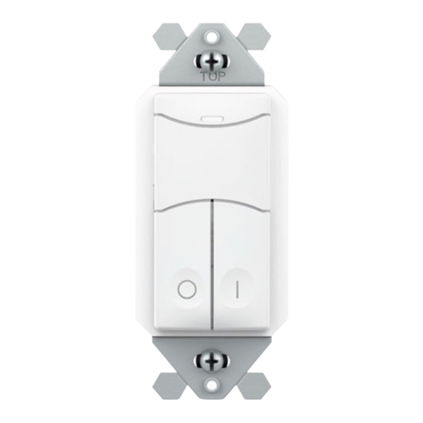
For three button units with integrated dimming, an additional 0-10V output wire is provided to connect directly to
xtures. By default, the lights will always come on to the last dim level, however the unit can be programmed to
turn-on to a preset level in order to accommodate partial-on applications.
FEATURES
Decorator Style Fits Common Wall Plates
(not included)
Less than 1” Depth in Wall
Multi-way Switching Capable (e.g., 3-way, 4-way)
Intuitive Operation
Matches Styling of SWX Wall Switch Sensor
Locator LED when Lights are Off
Modern Look and Intuitive
Easy-Tap Button for On/Off, Raise, & Lower
Five Segment LED Indication of Dim Level
Congurable Dimming Parameters (High/Low
Trims, Turn on Levels, Fade Rates, and Curve
Types)
Settings are Adjustable Without Removing Cover
Plate
CATALOG NUMBERS DESCRIPTIONS
SWX-801-xx LOW VOLTAGE MOMENTARY SWITCH
SWX-803-xx LOW VOLTAGE 0-10V DIMMING SWITCH
SPECIFICATIONS
ELECTRICAL
OPERATING VOLTAGE
5-24 VDC
CURRENT DRAW
2mA
DIMMING LOAD (Model # SWX-803 only)
50mA, (0-10 VDC ballasts or drivers compliant
with IEC 60929 Annex E.2)
MOMENTARY PULSE LENGTH
250 msec
PHYSICAL
SIZE
2.74”H x 1.68”W x 1.39”D
(6.96 x 4.27 x 3.53 cm)
Fits Decorator Switch Plate Opening
DEPTH IN WALL
0.94” (23.88 mm)
WEIGHT
2.5 oz
MOUNTING
Single Gang Switch Box
ENVIRONMENTAL
OPERATING TEMP
32°F to 122°F (0°C to 50°C)
RELATIVE HUMIDITY
0-95% Non-Condensing,
Indoor Use Only

YEL
BRN
SWITCH OUTPUT
RED
BLK
BRN
RED
RED
BLK
BLK
BLU
YEL
BLK
BLU
WHT
WHT WHT
N
277V
120V 120V/
277V
OR
CONTROL INPUT
COMMON
+VDC
SWITCH INPUT
RELAY STATUS
LOAD
CLASS 1
WIRING
CLASS 2
WIRING
* CAP UNUSED BLACK OR YELLOW WIRE
*
*
SWX-900-AX
POWER
PACK
SWX
LOW
VOLTAGE
SENSOR
SWX-801
SWITCH
YEL
RELAY STATUS INPUT
**
** IF NO SENSOR, CONNECT
WHITE WIRE TO RED WIRE
RED
BLK
COMMON
+5-24 VDC
SWITCH OUTPUT
BRN
SWX-801
SWITCH
YEL
RELAY STATUS INPUT
RED
BLK
COMMON
+5-24 VDC
VIO
0-10 VDC DIMMING OUTPUT
CONTROL OUTPUT
BRN
SWX-803
DIMMER
SWITCH
YEL
RELAY STATUS INPUT
WIRING
MANUAL ON APPLICATION (VACANCY)
Default operation of the SWX-900-AX is Automatic On (Occupancy) operation. For proper vacancy operation,
the SWX-900-AX’s OPERATIONAL MODE setting needs to be congured for MANUAL ON (VACANCY).
Additional SWX-801 switches can be wired in parallel to achieve 3-way (or more) operation.
STANDARD WIRING
WHT
+
VIO VIO
0-10 VDC DIMMING OUTPUT
BRN
YEL
RELAY STATUS
RED
BLK
RED
BLK
BLU
YEL
BLK
BLU
WHT WHT
N
277V
120V 120V/
277V
OR
CONTROL INPUT
COMMON
+VDC
CLASS 1
WIRING
CLASS 2
WIRING
*
–
*
SWX-900-AX
POWER PACK
SWX
LOW
VOLTAGE
SENSOR
GRY
* CAP UNUSED BLACK OR YELLOW WIRE
BRN
RED
SWITCH OUTPUT
BLK
SWX-803
DIMMER
SWITCH
SWITCH INPUT
0-10V DIMMABLE LOAD
YEL
RELAY STATUS INPUT
** IF NO SENSOR, CONNECT
WHITE WIRE TO RED WIRE
**
MANUAL ON (VACANCY) OR PARTIAL-ON w/ FULL DIMMING CONTROL
Lights turn on to last selected level (default) or to preset level (e.g., partial on).
If no sensor is present, tie power pack low voltage red to low voltage white wire.
Default operation of the SWX-900-AX is Automatic On (Occupancy) operation.
For proper vacancy or partial-on operation, the SWX-900-AX’s OPERATIONAL
MODE setting needs to be congured for MANUAL ON (VACANCY).

FRONT SIDE
BREAK-OFF
BRACKET EARS
BREAK-OFF
BRACKET EARS
LED INDICATOR
BUTTON
SENSOR FACE**
2.74”
SUPPLIED MOUNTING SCREWS
FOR MOUNTING TO
SINGLE GANG SWITCH BOX
1.39”
0.94”
1.69”
BREAK-OFF
BRACKET EARS
BREAK-OFF
BRACKET EARS
5 LED INDICATORS
RAISE
ON/OFF BUTTON
LOWER
SENSOR FACE**
2.74”
1.69”
** SENSOR FACE IS FIELD REMOVABLE IN ORDER TO CHANGE COLORS. CONTACT FACTORY FOR ADDITIONAL FACES
INSTALLATION
Designed to mount in 1-gang wall box with 3.28” hole spacing. Units can also share multiple gang wall boxes with other devices.
** SENSOR FACE IS FIELD REMOVABLE IN ORDER TO CHANGE COLORS. CONTACT FACTORY FOR ADDITIONAL FACES
CONFIGURATION SETTINGS
CONFIGURATION PROGRAMMING
1From the lists of Conguration Functions below, note the Button Position and number (#) of the Function to be changed. For example, HIGH TRIM setting is the Right Button, #3.
2Enter programming mode by pressing and holding the CENTER button until the blue LED begins rapid ashing.
3Press and release the applicable button for the chosen function. For example, press the RIGHT button 3 times for the HIGH TRIM setting.
4The LED will ash back the setting number of the current value as it appears in each function’s detailed table of values (see following pages). For example, the default HIGH TRIM is
setting #2 (10V) for the RIGHT button.
5Press and release the applicable button the number of times equal to the new setting #. For example, RIGHT button 3 times (for 9V).
6The LED will ash back the new setting number as conrmation.
7To save and exit programming mode, press and hold the function’s applicable button again until the LED ashes rapidly. The LED will then blink white twice as conrmation of success.
NOTE IF THE LED DOUBLE FLASHES TWICE BLUE AT ANY POINT, REPEAT THE ABOVE PROCEDURE.
CENTER BUTTON
FUNCTION NAME BUTTON POSITION FUNCTION #
LED Center 7
Factory Reset Center 8
LEFT BUTTON
DIMMING
FUNCTION NAME BUTTON POSITION FUNCTION #
Turn Off Scheme Left 2
Low Trim Left 3
Fade Off Time Left 4
RIGHT BUTTON
DIMMING
FUNCTION NAME BUTTON POSITION FUNCTION #
Turn On Dimming Level Right 2
High Trim Right 3
Fade On Time Right 4
Dimming Curve Type Right 5
CONFIGURATION FUNCTIONS
5 LED INDICATORS

CONFIGURATION SETTINGS CONT.
LEFT FUNCTION #2 TURN OFF SCHEME
LEFT BUTTON
SETTING # VALUES NOTES
2Unit fades to low trim and signals
relay to open Default for all models
3
Unit fades dimming output down to 0
volts (i.e. below a connected driver’s
electronic off level). Relay remains
closed
4Unit fades dimming output down to
low trim level. Relay remains closed
RIGHT FUNCTION #2 TURN ON DIMMING LEVEL
RIGHT BUTTON
SETTING # VALUES NOTES
2 Fade on to 100% of High Trim
3 Fade on to 50% of High Trim
4 Fade on to last user level Default
5 Fade on to current (custom) level Saves unit’s current dim level
LEFT FUNCTION #3 LOW TRIM
LEFT BUTTON
SETTING # VALUES NOTES
2 Saves current level as low trim
3 0%
Exact output voltage level depends on
Dimming Curve selected (e.g. Linear,
Log). Light output at each level depends
on driver/ballast and luminaire.
4 10% (Default)
5 20%
6 30%
7 40%
8 50%
RIGHT FUNCTION #3 HIGH TRIM
RIGHT BUTTON
SETTING # VALUES NOTES
2 Saves current level as high trim
3 100% (default)
Exact output voltage level depends on
Dimming Curve selected (e.g. Linear,
Log). Light output at each level depends
on driver/ballast and luminaire.
4 90%
5 80%
6 70%
7 60%
8 50%
LEFT FUNCTION #4 FADE OFF TIME
LEFT BUTTON
SETTING # VALUES NOTES
2 0.75 Sec
3 1.5 Sec Default for all models
4 3 Sec
5 5 Sec
6 15 Sec
RIGHT FUNCTION #4 FADE ON TIME
RIGHT BUTTON
SETTING # VALUES NOTES
2 0.75 Sec
3 1.5 Sec Default for all models
4 3 Sec
5 5 Sec
6 15 Sec
LEFT FUNCTION #5 MANUAL DIMMING RESPONSE CURVE
RIGHT BUTTON
SETTING # VALUES NOTES
2 Linear Default for all models
3 Log
4 Square Log
CENTER FUNCTION #7 LED FUNCTION
CENTER BUTTON
Single button switch (SWX-801) has an LED that is white when lights are on and is a blue locator LED when lights
are off. Dimming switch (SWX-803) has ve white LEDs that indicate the current dim level. Locator LED can also
be programmed to be be white and/or brighter. Locator LED can also be disabled
SETTING # DESCRIPTION NOTES
2 White LED when lights on, blue locator LED when off, normal brightness Default
3 Blue LED when lights on, white locator LED when off, normal brightness
4 All LED functionality disabled.
5 White LED when lights on, blue locator LED when off, increased brightness
6 Blue LED when lights on, white locator LED when off, increased brightness
CENTER FUNCTION #8
RESTORE FACTORY DEFAULTS
CENTER BUTTON
SETTING # DESCRIPTION
3 Restore Factory Defaults
This manual suits for next models
1
Other SENSORWORX Switch manuals
