SENSORWORX SWX-852-B Series Installation instructions

WIRELESS
REMOTE DIMMER
& SWITCH
INSTALLATION & OPERATION INSTRUCTIONS
SPECIFICATIONS
ELECTRICAL & WIRELESS
BATTERY TYPE
Requires one CR123(A) Lithium Battery
(provided in box)
BATTERY LIFE
Designed for 10 Year Life
Non-Volatile Memory (saves all
settings regardless of battery state)
Blink Warning @10% Life
RANGE
80’ line of site w/o obstruction (walls)
40’ with obstruction (walls/oors)
FREQUENCY
915 MHz ISM Band
WIRELESS LINKING
Simple 3 sec. Push Button Process
SECURITY
All Wireless Data is Encrypted
CODE COMPLIANCE
These switches can be used to meet
ASHRAE 90.1, IECC, & Title 24 energy
code requirements.
ENVIRONMENTAL
OPERATING TEMP
32°F to 122°F (0°C to 50°C)
RELATIVE HUMIDITY
0-95% Non-Condensing,
Indoor Use Only
PHYSICAL
SIZE
2.74”H x 1.68”W x 1.39”D
(6.96 x 4.27 x 3.53 cm)
Fits Decorator Switch Plate Opening
WEIGHT
2.5 oz
MOUNTING
Single Gang Switch Box
MISC
COMPATIBLE LOAD CONTROLLERS
SWX-851 Wall Switch
SWX-950 Series Power Packs
FEATURES
à Pairs in Seconds with Wireless
Controllers
à 10 Year Battery Life Design
à Decorator Style Fits Common Wall
Plates (not included)
à Matches Styling of other SWX
Sensors & Wired Wall Stations
à Enables Multiway Switching &
Dimming (e.g., 3-way, 4-way)
à Intuitive Operation
OVERVIEW
The SENSORWORX®remote dimming and on/off wall stations are battery powered
devices that provide manual operation of wirelessly controlled lighting. These attractive
wall stations greatly reduce total installation time and wireless pairing fuss. Requiring
just a few seconds per device, SENSORWORX wireless sensors can be linked to one or
more wireless load controllers (such as the SWX-851 wireless wall switch, or a SWX-
950 series wireless power pack). Additionally, these devices can be congured to work
together with other wireless or wired wall stations to provide dimming and switching
control from multiple locations.
MODEL NUMBERS DESCRIPTION
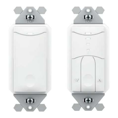
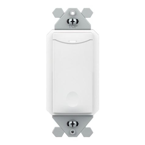
SWX-852-B-xx WIRELESS REMOTE 2 BUTTON ON/OFF WALL STATION,
BATTERY POWERED
SWX-854-B-xx WIRELESS REMOTE DIMMING & ON/OFF WALL STATION,
4 BUTTON, BATTERY POWERED
LINE VOLTAGE 0-10V DIMMING
WIRELESS
REMOTE
DIMMER
SWITCH
WIRELESS
DIMMING
POWER
PACK
WIRELESS
CEILING
SENSOR
APPLICATIONS
Adding a wireless remote wall switch to a room controlled by a wireless power
pack (SWX-950) and a wireless sensor (e.g. SWX-201-B) enables code compliant
vacancy (manual on) operation. When linked with a wireless dimming power pack
(SWX-950-D2), a remote wireless dimmer is perfect for providing user control
of 0-10V dimmable lighting. Additional remote dimmer switches can be linked
enabling user control from multiple locations. Linking a remote wireless switch to
a wireless wall switch load controller (SWX-851) enables 3-way user control as
well.
à Classrooms
à Open Areas
à Conference Rooms
à Hallways
à Small Ofces
à Copy Rooms
à Private Restrooms
à Break Rooms
* xx = color (WH, IV, AL, GY)

à The switch/dimmer runs on one CR123(A) Lithium Battery (included).
à Install battery prior to mounting. Polarity is indicated on the battery compartment
door.
à If the unit’s battery life reaches 10%, the LED will rapidly blink blue after every
button press.
à Replacement batteries are available at most retailers or home centers where
batteries are sold or from SENSORWORX.
BATTERY INFORMATION
COMPATIBLE WIRELESS DEVICES
The below chart lists the devices that can be used in a SENSORWORX wireless application. Note that sensors and remote switch & dimmer devices are transmit only devices and
therefore must be linked to a load controller for switching or dimming of lighting.
MODEL # DESCRIPTION WIRELESS TYPE POWER TYPE
SWX-201-B Small Motion 360° Sensor, PIR Transmit Battery
SWX-401-B Wide View Sensor, PIR Transmit Battery
SWX-402-B Long Range Hallway Sensor, PIR Transmit Battery
SWX-851-xx Wall Switch Load Controller, No Neutral Required, <xx = color> Transmit & Receive 120-277 VAC
SWX-852-B-xx Remote Switch (On/Off), <xx = color> Transmit Battery
SWX-854-B-xx Remote Dimming Switch (On/Off, Raise/Lower), <xx = color> Transmit Battery
SWX-950 Power Pack Load Controller, 20A Receive 120/277 VAC
SWX-950-D2 Power Pack Load Controller, 20A, 0-10V Dimming Receive 120/277 VAC
SWX-950-AX Hybrid Wireless/Wired Power Pack Load Controller, 20A Transmit & Receive 120/277 VAC
SWX-950-AX-D2 Hybrid Wireless/Wired Power Pack Load Controller, 20A, 0-10V Dimming Transmit & Receive 120/277 VAC
MOUNTING
BRACKET
CHASE NIPPLE
BATTERY
COMPARTMENT
BATTERY
COMPARTMENT
BATTERY
COMPARTMENT
LOCK NUT
CHASE NIPPLE
LOCK NUT
LOCKING 3-POSITION
TILT ADJUSTMENT
MOUNTING
BRACKET
LOCKING 3-POSITION
TILT ADJUSTMENT
SERRATED END
FOR CUTTING
THROUGH
CEILING TILE
SERRATED END FOR CUTTING
THROUGH CEILING TILE
INSTALLATION INSTRUCTIONS
à Designed to mount in 1-gang wall box with 3.28” hole spacing.
à Units can also share multiple gang wall boxes with other devices.
LED INDICATOR
LED INDICATOR
DIMMING UP
DIMMING DOWN
ON BUTTON
OFF BUTTON
ON BUTTON
OFF BUTTON
LED INDICATOR
LED INDICATOR
DIMMING UP
DIMMING DOWN
ON BUTTON
OFF BUTTON
ON BUTTON
OFF BUTTON
SWX-852 SWX-854
OPERATION NOTES
à Wireless remote switches and dimmers only transmit when a button is being pressed.
à The unit’s blue LED will light only when a button is pressed.
à The dim up and dim down buttons may be held down to increase dimming rate.

STEP 1
WALL SWITCH OR POWER PACK
STEP 2 & STEP 3
WIRELESS REMOTE SWITCH & DIMMER
STEP 4
WALL SWITCH OR POWER PACK
SWX-851
HOLD
FOR 3 SEC
SWX-950
HOLD
FOR 3 SEC
SWX-854
HOLD
FOR 3 SEC
SWX-852
HOLD
FOR 3 SEC
SWX-851
PRESS ONCE
SWX-950
PRESS ONCE
OR OR
WIRELESS PAIRING
Pairing a remote dimmer/switch with a wireless wall switch load controller or power pack load controller is quickly done via the following procedure:
1. Enter pairing mode by holding down the wireless load controller’s button for 3 seconds until the LED starts alternating white then blue.
2. At the battery powered remote dimmer/switch, hold down the ON button for 3 seconds until the LED starts alternating white then blue. Releasing will pair the device with the
controller in pairing mode (see note 1 below). The lights will toggle once as conrmation.
3. If additional remote dimmers or switches need to be linked, repeat step 2.
4. When all devices have been paired, close pairing mode on the wireless load controller by pressing the button 1 time. Pairing will also be automatically closed after 15 minutes of no
new devices being linked.
Note 1: When in pairing mode, the alternating LED colors on the wireless load controller will periodically pause and blink out the total number of paired devices. There will be no blinks
during the pause until the rst device is linked.
CONFIGURATION MISC.
UNPAIRING FROM LINKED LOAD CONTROLLERS
To unpair a wireless remote dimmer or switch from all wirelessly linked load controllers execute the following “FORGET ME” procedure.
ENTERING A “FORGET ME” COMMAND
1Enter programming mode by pressing and holding the ON button for at least 6 seconds until the LED begins ashing blue only, then release.
2Press and release the unit’s pushbutton 8 times, then wait 2 seconds.The White LED will blink back 2 times, pause and repeat.
3Interrupt the blink back and press the ON button 4 times. The LED will blink back 4 times as conrmation, pause then repeat.
4Interrupt the conrmation blink back and press and hold the ON button until blue LED changes to white, then release. The LED will then blink white twice as conrmation of success.
Note: To Exit without saving during any step, release button and wait until the unit double ashes blue.

Five-Year Limited Warranty.
Complete Warranty Terms Located at: sensorworx.com/warranty
INS854 | REV 001–200611
SENSORWORX | 2a Research Parkeway, Wallingford CT 06492
203.678.4224 | www.sensorworx.com
© 2020 BLP Technologies, Inc. All rights reserved.
FCC INFORMATION (FCC ID: 2AVRY-SWX0001)
ISED CANADA INFORMATION (IC: 26012-SWX0001)
This device complies with Part 15 of the FCC Rules. Operation is subject to the following conditions:
1. This device many not cause harmful interference, and
2. This device must accept any interference received, Including interference that may cause undesired operation
Changes and Modications not expressly approved by BLP Technologies can void your authority to operate this equipment under Federal Communications Commission’s rules.
In order to comply with FCC/ISED RF Exposure requirements, this device must be installed to provide at least 20 cm separation from the human body at all times.
This equipment has been tested and found to comply with the limits for a Class B digital device, pursuant to Part 15 of the FCC Rules. These limits are designed to provide reasonable protection against
harmful interference in a residential installation. This equipment generates uses and can radiate radio frequency energy and, if not installed and used in accordance with the instructions, may cause harmful
interference to radio communications. However, there is no guarantee that interference will not occur in a particular installation. If this equipment does cause harmful interference to radio or television
reception, which can be determined by turning the equipment off and on, the user is encouraged to try to correct the interference by one of the following measures:
• Reorient or relocate the receiving antenna.
• Increase the separation between the equipment and receiver.
• Connect the equipment into an outlet on a circuit different from that to which the receiver is connected.
• Consult the dealer or an experienced radio/TV technician for help
This device contains licence-exempt transmitter(s)/receiver(s) that comply with Innovation, Science and Economic Development Canada’s licence-exempt RSS(s). Operation is subject to the following two
conditions:
1. This device may not cause interference.
2. This device must accept any interference, including interference that may cause undesired operation of the device.
In order to comply with FCC/ISED RF Exposure requirements, this device must be installed to provide at least 20 cm separation from the human body at all times.
L’émetteur/récepteur exempt de licence contenu dans le présent appareil est conforme aux CNR d’Innovation, Sciences et Développement économique Canada applicables aux appareils radio exempts de
licence. L’exploitation est autorisée aux deux conditions suivantes :
1. L’appareil ne doit pas produire de brouillage;
2. L’appareil doit accepter tout brouillage radioélectrique subi, même si le brouillage est susceptible d’en compromettre le fonctionnement.
3. An de se conformer aux exigences d’exposition RF FCC / ISED, cet appareil doit être installé pour fournir au moins 20 cm de séparation du corps humain en tout temps
This manual suits for next models
1
Other SENSORWORX Switch manuals
