Sensory Analytics Specmetrix SA User manual


2 | P a g e
R e v 5 - 1 9
Table of Contents
System Description and Usage.................................................................................................................. 7
Product Safety........................................................................................................................................... 7
System Specifications.........................................................................................................................8
Performance Specifications ...................................................................................................................... 8
Environmental Specifications-Customer must provide ............................................................................ 8
Installation and Site Requirements........................................................................................................... 9
Utilities ...................................................................................................................................................... 9
Electronics Mounting and Conduit Work................................................................................................ 10
Probe Installation.................................................................................................................................... 10
Laser Detection Setup ............................................................................................................................. 11
Network and Machine Communications ................................................................................................11
Emergency Stop ...................................................................................................................................... 11
System Start-Up Procedure..................................................................................................................... 12
System Shut down Procedure.................................................................................................................13
Signing On ............................................................................................................................................... 14
SA Services ......................................................................................................................................14
Change User ....................................................................................................................................14
SA UI Configuration..........................................................................................................................15
ColorBands.............................................................................................................................................. 15
CrossWeb ................................................................................................................................................ 15
CrossWeb Line Count
.......................................................................................................................... 15
Default User ............................................................................................................................................ 15
Default Password ................................................................................................................................ 15
Default User Id .................................................................................................................................... 15
Inline ....................................................................................................................................................... 16
Cross web Position Update Rate ......................................................................................................... 16
Decimal Places .................................................................................................................................... 16
Downweb Graph Count....................................................................................................................... 16
Graph Configs Cross Web / Die / Down Web / Lanes / Polar.............................................................. 16
Display Thickness on Bar Graph .......................................................................................................... 16
Invert Crossweb Graph .......................................................................................................................16
Smooth? ..............................................................................................................................................16

3 | P a g e
R e v 5 - 1 9
Smoothing Count ................................................................................................................................ 16
Smoothing Level..................................................................................................................................17
Multi-line Graph Display .....................................................................................................................17
Posted Readings Averaged..................................................................................................................17
Polar Graph Config ..............................................................................................................................17
Traverse Left-side Name ..................................................................................................................... 17
Traverse Right-side Name...................................................................................................................17
Logging .................................................................................................................................................... 17
Logging Interface................................................................................................................................. 17
Login Security.......................................................................................................................................... 17
Login Timeout ..................................................................................................................................... 17
Probe Colors............................................................................................................................................ 18
SA ACS ..................................................................................................................................................... 18
SA Blown Film Settings............................................................................................................................ 18
SA Inline (Fixed Differential) ................................................................................................................... 18
Show Base Value ................................................................................................................................. 18
Show Total Value ................................................................................................................................ 18
SA Menu.................................................................................................................................................. 18
Menu Scaling....................................................................................................................................... 18
Shutdown Method .............................................................................................................................. 18
SA Offline (DFT-QA)
................................................................................................................................. 18
SA PLC Traverse Settings......................................................................................................................... 18
Pic Traverse User Options ................................................................................................................... 18
(Fixed Width) Lane Width ................................................................................................................... 18
(Left/Right) Web Percentage .............................................................................................................. 19
Constant Lane Count........................................................................................................................... 19
Relative Distance Unit......................................................................................................................... 19
Web Division Type............................................................................................................................... 19
SA Sheet Type Settings............................................................................................................................ 19
SpecMetrix® SA Data Manager ...................................................................................................................20
General Information ............................................................................................................................... 21
Command Bar ..................................................................................................................................... 21
Data Services Group............................................................................................................................ 21

4 | P a g e
R e v 5 - 1 9
New Group ..........................................................................................................................................21
Database Group ..................................................................................................................................21
Delete Group....................................................................................................................................... 22
Screen Control (Recipe Module Only).................................................................................................22
Filter Region ........................................................................................................................................ 22
Selection Region.................................................................................................................................. 22
View Detail Region .............................................................................................................................. 23
Module Navigation Region.................................................................................................................. 23
Recipes ....................................................................................................................................................24
Recipe Assistant ......................................................................................................................................25
Getting Started with the Recipe Assistant .............................................................................................. 25
Lanes (SpecMetrix® Traversing Only)...................................................................................................... 31
Adding / Editing a Lane Definition .......................................................................................................... 32
Users ....................................................................................................................................................... 34
User Permission levels and their privileges ............................................................................................ 34
Plants....................................................................................................................................................... 35
SpecMetrix® SA Inline Measurements...............................................................................................37
Main User Interface ................................................................................................................................ 37
Adjustable Target Set.......................................................................................................................... 38
Statistics Tab ....................................................................................................................................... 38
Distance to Target............................................................................................................................... 38
Debug .................................................................................................................................................. 39
User Interface Tabs ................................................................................................................................. 40
Thickness Graph.................................................................................................................................. 40
Average Reads..................................................................................................................................... 40
Thickness Data .................................................................................................................................... 41
Historical ............................................................................................................................................. 41
Traversing................................................................................................................................................ 42
Cross Web ........................................................................................................................................... 42
Lane Graph.......................................................................................................................................... 43
Die Graph ............................................................................................................................................ 43
Light Tower ............................................................................................................................................. 44
In-line Wave Analysis Tool................................................................................................................45

5 | P a g e
R e v 5 - 1 9
Getting Started............................................................................................................................................ 45
Logging Inline Graph ...........................................................................................................................45
Loading Files........................................................................................................................................ 45
Controls............................................................................................................................................... 46
Calculated Thickness........................................................................................................................... 47
Normalized Data ................................................................................................................................. 47
Raw Data ............................................................................................................................................. 48
Peak Data ............................................................................................................................................ 48
PA Settings .......................................................................................................................................... 52
Layer Settings...................................................................................................................................... 53
Specification & Graph Setup ............................................................................................................... 54
Overview Grid ..................................................................................................................................... 55
Gravimetric ......................................................................................................................................... 55
Making changes with Analysis Tool ........................................................................................................ 56
WHAT TO CHANGE AND HOW IT AFFECTS YOUR READING ..................................................................................................... 56
Peak Tolerance.................................................................................................................................... 56
Fringe Variance ...................................................................................................................................56
Height Threshold................................................................................................................................. 56
Custom Smoothing.............................................................................................................................. 57
Momentum ......................................................................................................................................... 57
Waveform Type................................................................................................................................... 57
Starting/Ending Wavelength............................................................................................................... 57
Index of Refraction.............................................................................................................................. 57
Min/Max Thickness............................................................................................................................. 57
Target Spec.......................................................................................................................................... 57
+/- Tolerance....................................................................................................................................... 57
SpecMetrix® On-Line Support...........................................................................................................58
Other SA Menu Buttons .......................................................................................................................... 59
System Maintenance .............................................................................................................................. 60
Suggested Cleaning Interval................................................................................................................ 60
Maintenance Procedures for Lab and In-line systems........................................................................ 60
Lamp Replacement for In-line Systems............................................................................................... 60
Probe Cleaning ....................................................................................................................................62

6 | P a g e
R e v 5 - 1 9
General Maintenance Checklist ..............................................................................................................62
Calibration...............................................................................................................................................62

7 | P a g e
R e v 5 - 1 9
System Description and Usage
The SpecMetrix® In-line coating thickness measurement system is designed to measure the thickness or
coat weight of wet or dry coatings applied to flat sheets, continuous coil or plastic film and coatings on
many other substrates. Each system is comprised of one or multiple probes connected by fiber optic
cable to a controls enclosure mounted near the coating line so that the supplied probe cables can
terminate in the controls enclosure. The probes are usually mounted between the coater and the oven
for wet coating measurement and after the oven for dry coating measurement. The enclosure has a
data connection to the SpecMetrix® Display Unit, which can be up to 150 feet (~50 meters) away.
SpecMetrix® systems use proprietary ruggedized optical interference technology to measure the
absolute wet or dry coating thickness. This is a non-contact and non-destructive technology that only
requires minimal prior knowledge of the refractive Index of the coating to evaluate the coating thickness
measurement in microns. When measuring wet coatings, the dry coat weight in units such as MgSI,
Mg4SI, lbs./ream or GSM is then calculated from the wet or dry thickness using data from the coating
manufacturer such as wet density (lbs./gallon or gram/liter) and % solids by weight and %solids by
volume.
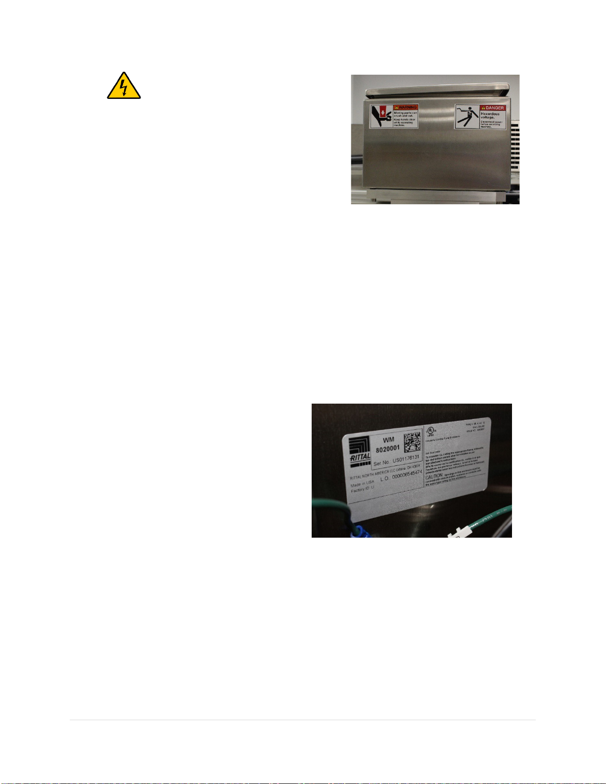
Product Safety
Before using your SpecMetrix® System
Your SpecMetrix® System is very safe to use. However, like all electronic equipment, you must follow
these common-sense guidelines to ensure your safety and future integrity of the unit.
•
Please read and follow instructions
It will be helpful if you review this document completely before you attempt to install and use
your SpecMetrix® System.
•
Retain this manual for future reference
Keep this manual handy for others to read and refer to when they operate the unit
•
Obey Warnings
Please follow all the precautions described in this manual. If you modify or use the SpecMetrix®
System in a manner not intended, the built-in safety features may be impaired.
•
Protect from water and moisture
Do not use your SpecMetrix® System in an area where there is a potential hazard of electric
shock from spilled water or other uncontrolled moisture.
8 | P a g e
R e v 5 - 1 9
•
Electrical Warning
A professional licensed electrician should perform all
electrical work/installation.
•
Installation Requirements
1. SpecMetrix traversing systems must be
installed inside a cage.
2. Indoor and dry location use only
3. Environmental temperature: 0-50C (32-122F)
4. System mounting elevation: Max 2m (6.5ft)
5. The weight of total system ~1000lbs (453kg, ICU weight 125lbs)
System Specifications
Performance Specifications
1. Coating Thickness Range 0.5 to 250 microns
2. Typical Accuracy 3%
3. Non-contact measurement range 15-33mm
Environmental Specifications-Customer must provide:
•
Dedicated Circuit
•
Single-Phase with neutral and ground
•
50/60Hz
•
120/240VAC
•
15Amp Circuit (min 14AWG (1.63mm
diameter wire)
•
SpecMetrix ICU can be hard-wired to the
main power input or a wall socket
•
Primary Operator Workstation will require
one or two wall sockets depending on the
configuration that must be in the same
dedicated circuit
•
All Ethernet cables must be minimum CAT 6 Shielded
•
ICU can be maximum of 65.5 feet (~20 meters) “cable-routing” distance away from actuators
•
Ethernet cables with a distance more than 45.72m/150ft MUST be converted to an armored
fiber optic multi-mode
•
Highly Recommended to use a 1000VA or better UPS.
1. SpecMetrix® Display Unit 6 amps @ 120VAC, 4 Amp @ 240VAC
2. Operating Humidity 10%-90% relative, non-condensing
3. ICU enclosure protection IP65/66
4. SpecMetrix® display protection IP65/66
9 | P a g e
R e v 5 - 1 9
SpecMetrix® Display Unit Requirements
SpecMetrix® will provide a display unit with at least the minimal requirements installed which are
Windows 7 64-bit (SP 1), 16GB Memory, and SSD storage.
Installation and Site Requirements
Utilities
The SpecMetrix® In-line system requires a dedicated 120VAC/240VAC AC 15-amp grounded mains
supply adjacent to the Display Unit and the In-line Control Unit. This means a direct connection back to
the fuse Unit.
The instrumentation should not be spurred off a thyristor-
controlled heater or motor due to the electrical interference
this would cause.
The Control Unit and Display Unit can be run on the same 15-
amp circuit. The Display Unit requires a standard
120VAC/240VAC receptacle; the Control Unit can either be
directly connected via conduit or use a standard
120VAC/240VAC single-phase receptacle.
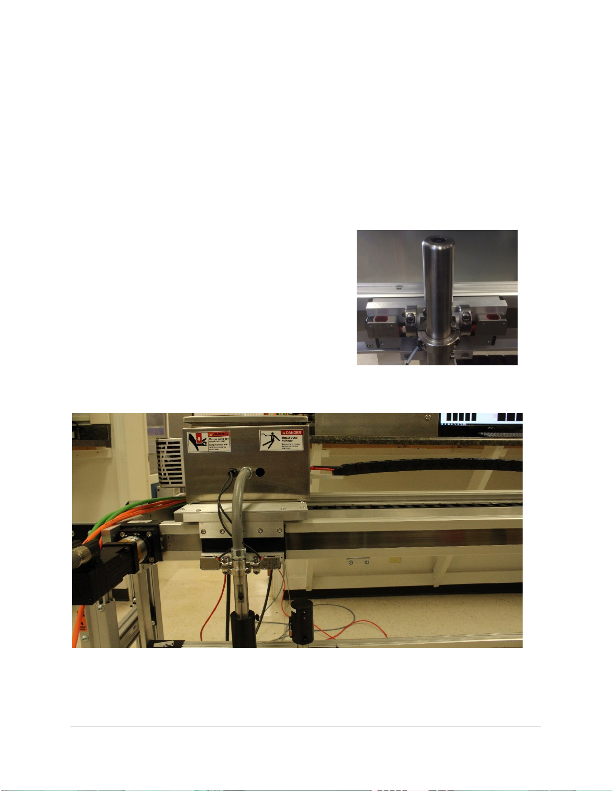
Ruggedized Probe Assembly
10 | P a g e
R e v 5 - 1 9
Electronics Mounting and Conduit Work
An on-site maintenance technician needs to be available to work with SA personnel to mount the probe
holder fixtures to the equipment frame. These attachments will vary depending on the type of system
purchased, and machine configuration.
The control Unit will require four 3/8” holes on a 20” x 20” area to mount.
The SpecMetrix® Display Unit can either be mounted to a supplied pedestal frame or a supplied swing-
arm mount system.
Sensory Analytics will supply the flexible conduit to be installed between the probes and Control Unit,
with the customer providing the means to tie or clamp the conduit down.
The customer is expected to supply and install conduit for an Ethernet connection between the Display
Unit and the Control Unit, and from the Control Unit to the customer’s network if external data storage
is required. Must use minimum CAT 6 Shielded Cable.
SA will supply, install and terminate the Ethernet cable unless agreed otherwise with plant personnel.
The probes are optical devices with no electrical connections and so can be mounted in an explosive
environment. The Control Unit, however, contains electrical components and is not designed for use in
an explosive environment. The fiber optic cables have a standard length of 30 feet and can be up to 60
feet long, and so the Control Unit can be mounted up to 50 feet from the probes and production line.
The Display Unit can be mounted up to 150 feet from the Control Unit.
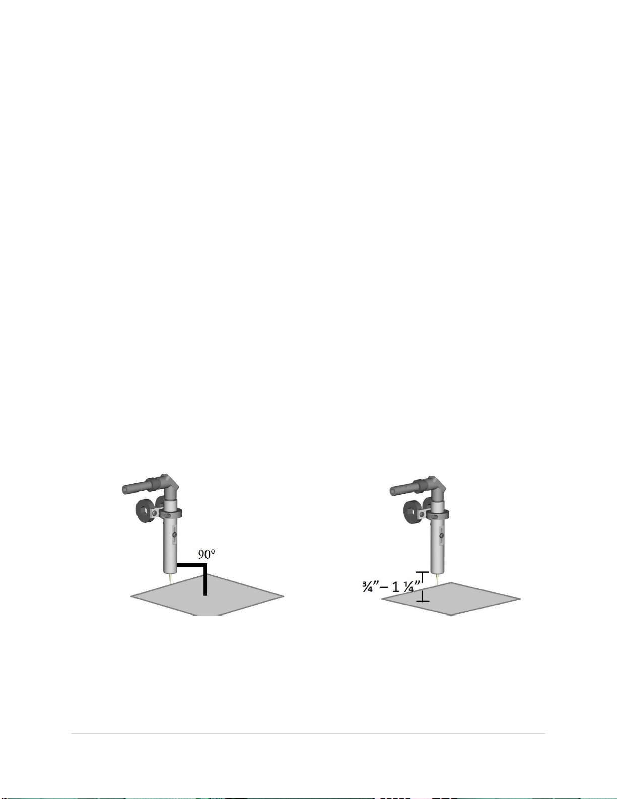
Probe Installation
Typically, Sensory Analytics technicians will install the probes ¾” – 1 ¼” over the web at a 90° angle using
a Hex bar and collar clamps. If a plant has constructed their own mechanism for probe mounting, the
mechanism must allow for probe height adjustment from ½ inch to 2 inches from the web.
11 | P a g e
R e v 5 - 1 9
Laser Detection Setup
Make sure laser is set to factory settings. (Hold the down
button and press the up button 5 times you should see an
“RST” on the LCD of the sensor, press up to get a “no” on
the LCD, then press “up” again and you will see “yes”, then
press “down” this will get you back to factory settings).
Move the sensor off of film, press the side button for 1 sec.
(It will flash “set”). Then press and hold side button till
“set” goes away. Do this for both sensors.
Network and Machine Communications
The SpecMetrix® Display Unit motherboards are designed with 2 or 3 Ethernet ports for various network
& peripheral communication needs. The Ethernet ports are configured for communication by Sensory
Analytics technicians or by plant IT engineers. When multiple devices need to communicate across
different networks or subnets, it is imperative to make sure the correct Ethernet cables are plugged into
the appropriate Ethernet port.
Plant network engineers are permitted to change the login configuration to use plant network
authentication. The requirement for any user account that will be given access to the SpecMetrix®
Display Unit is to have local admin access as well as proper access to read/write to any network path
that is defined as a file repository. It is permitted, and recommended, to use file mapping to network
paths.
For the main electrical cable, run a properly terminated (Line, Neutral, and Ground) power cable to the
side of the ICU to the clamshell connector provided on the panel mount. (connections are labeled). All
internal power is already wired appropriately.
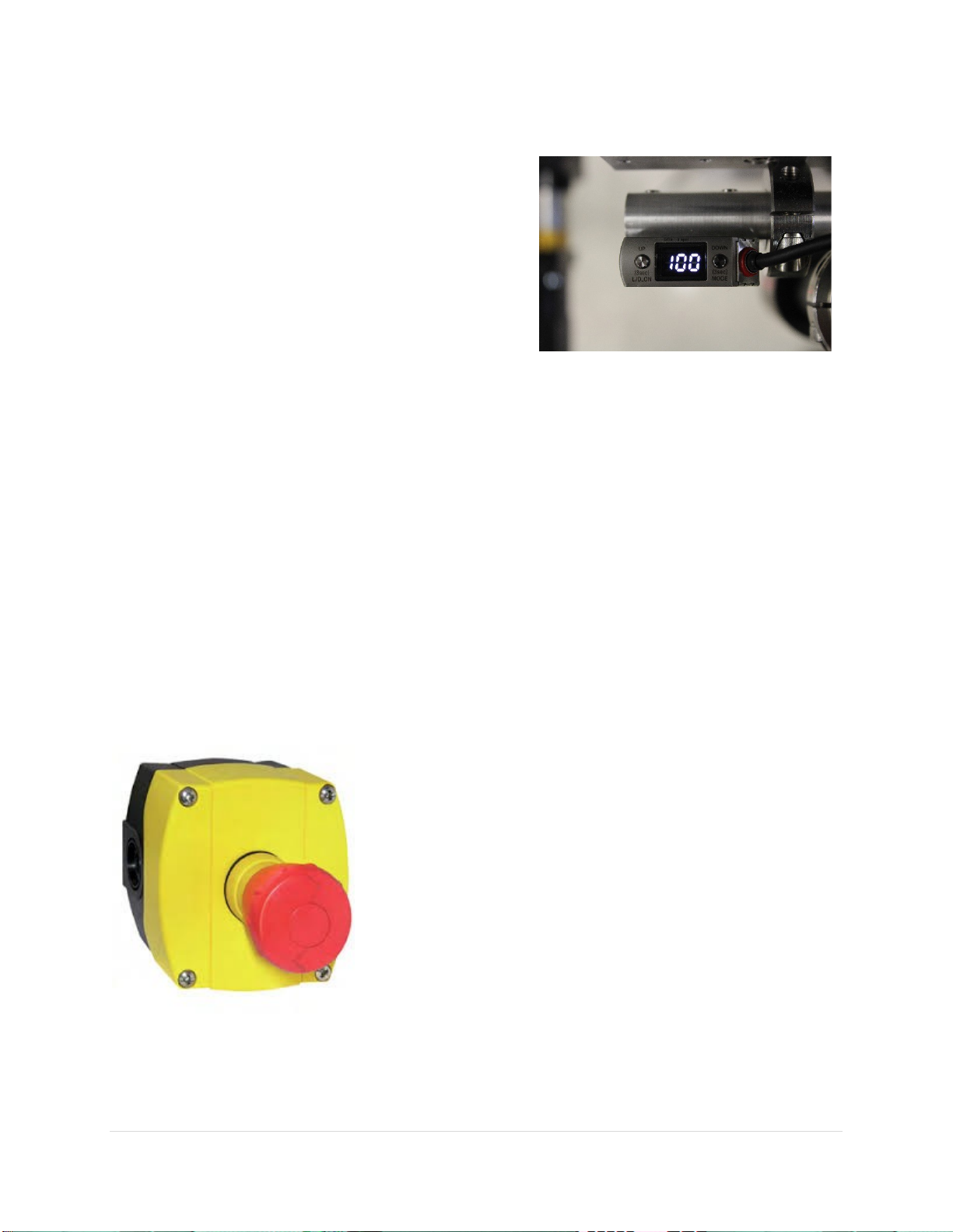
Emergency Stop
SpecMetrix Traversing systems come with an Emergency Stop (E-
Stop) push button (refer to provided electrical schematics for
wiring).
When the E-Stop is engaged, it will disengage controls to the
servo drives causing them to cease motion. A signal is also sent
to ‘Stop’ the Inline software from measuring.
While the E-Stop is engaged the servo drives will not be able to
move the probe head, and SA Inline cannot measure. The probe
head can be moved by hand when the E-Stop is engaged.
Ensure the probe is free from obstruction before releasing the E-
Stop. The E-Stop is released by turning the red mushroom head to
the “right” which will release the button and pop it out. Once the E-Stop is released, the probes will
move to their park position.

12 | P a g e
R e v 5 - 1 9
System Start-Up Procedure
Turn the Disconnect on the main electrical cabinet to the “ON”
position. The green light on the front should illuminate.
Wait a minute for the background
services to start. Then press the SA
service red tile. The screen will gray out
while starting the service.
Once the SA service tile goes green, the
system is ready to use.

13 | P a g e
R e v 5 - 1 9
System Shut down Procedure
Select the green “SA Service” Tile. Then Select “Yes” to properly shut down the SA service.
Select the red “Windows Shutdown” tile. This will start the computer shutdown process. Then select
“Yes” to shut down the computer.
Turn the Disconnect to the “OFF” position to power down the
ICU.
14 | P a g e
R e v 5 - 1 9
Signing On
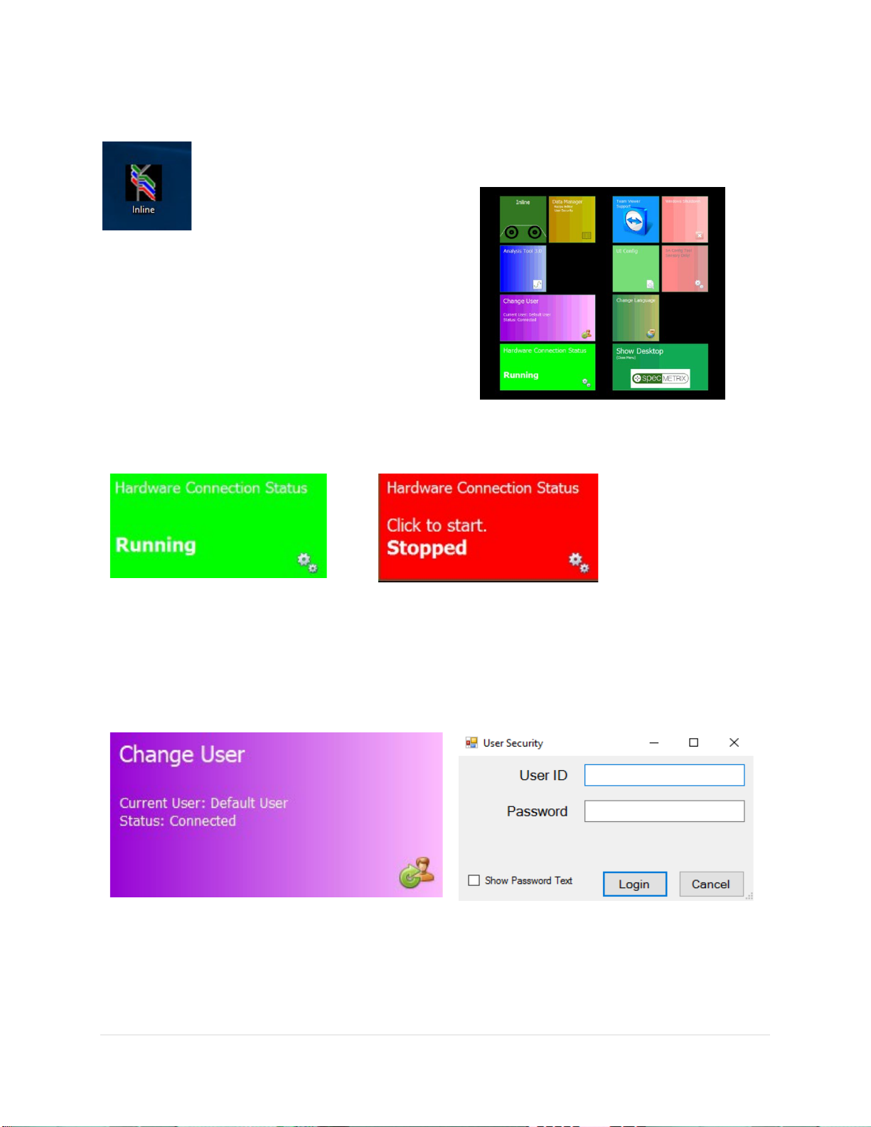
Double-click the Sensory Menu icon on the desktop.
Full SA Menu window will open as seen in the image below. The arrangement of your
tiles may vary slightly.
Full SA Menu window will open as seen in the image
below. The arrangement of your tiles may vary slightly.
SA Services
Make sure the Server Status is running (Indicated as a Green Color). If Server Status is Stopped (Red
Color), click the Server Status Tile once.
Change User
By Default, SA will be logged in as a Base Level User named Default. This allows for limited view only
rights into SA.
To log in as a different user click on the “Change User” Tile. You will see a popup window appear in the
upper left corner of the screen for you to enter your credentials.
There are five different user levels one can have. There is a User, Supervisor, Local Admin, Corporate,
and Corporate Admin. This will be discussed in greater detail later in this guide.

15 | P a g e
R e v 5 - 1 9
SA UI Configuration
SA UI Configuration – Used to adjust graph settings, minimum and
maximum measurement ranges, target specifications. They are also used to
change aspects of the In-line system such as the color of the High/Low
measurement on the display, or to apply alternative smoothing to a graph,
and the option to set your graphs to be tabbed or side-by-side in multi-line
systems. In most cases, values can be changed by clicking on the value field
until the desired setting appears. Select the SAVE button to save any
changes made. Requires Local Admin Access or higher.
ColorBands
Percentage of the graph the at the band occupies. By default, GREEN = 50, YELLOW = 25, RED = 25
CrossWeb
CrossWeb Line Count
Number of Cross Lines to display
Default User
Default Password
Enter a valid password for assigned PlantID auto login when SA initializes
Default User Id
Enter a valid username for assigned PlantID auto login when SA initializes

16 | P a g e
R e v 5 - 1 9
Inline
Graphing options for CrossWeb Graph, Die Graph, DownWeb Graph, and Lane Graph
Cross web Position Update Rate
[1-10] Lower value increases the number of Positions Line updates but can cause screen
unresponsiveness and lag.
Decimal Places
The number of decimal places measurement readings will display.
Downweb Graph Count
Scrolling size: the graph number of graph points displayed for each probe on the down web graph.
*Note: Setting this value very high will cause the graph to respectively draw across very slowly (Max
3600; 1-hour of date for single probe).
Graph Configs Cross Web / Die / Down Web / Lanes / Polar
Configuration options
Display Thickness on Bar Graph
Display the thickness of the region inside the Bar on the graph.
Invert Crossweb Graph
This will flip the graph on its x-axis.; Options are True or False.
Smooth?
Setting this to True will apply a smoothing algorithm to the averages. This may cause slight
differences between numbers plotted on a graph and the value displayed in the Probe Reading.
Options are True or False.
Smoothing Count
Increasing this number will smooth the plot lines from point to point on graphing displays. Set
to 5 by default.
17 | P a g e
R e v 5 - 1 9
Smoothing Level
A higher level will show more stable results but will take longer to show changes in the coating.
Multi-line Graph Display
How multiple graphs are drawn in relation to one another. Options include None, SidebySide, Tabbed,
and Combination*. * Combination Type exclusively for Traversing systems.
Posted Readings Averaged
Count of reading cycles to use for calculating the held average. Only used for Average Reads Tab. Values
shown may not represent recent data. The default is set to 5.
Polar Graph Config
This portion of the config file does not pertain to the Traversing System
Status Display Type
Configuration options for Cross Web
Traverse Left-side Name
A label for the left side of traversing sides
Traverse Right-side Name
A label for the right side of traversing sides
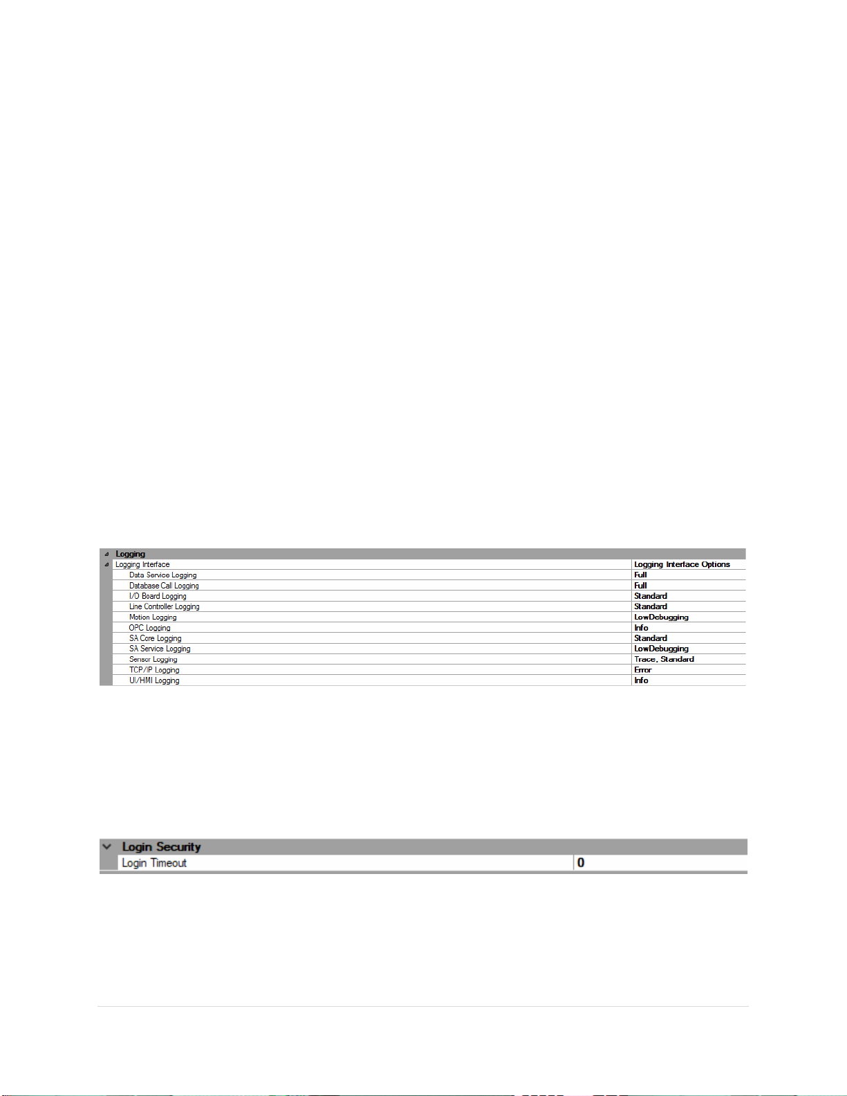
Logging
Logging Interface
Set condition levels for the following Logging Interface; Data Service, Database Call, I/O Board, I/O
Boards, Line Controller, Motion, OPC/PLC, SA Core, SA Service, Optical Sensor, TCP/IP, and UI/HMI.
Logging Conditions: OFF, FULL, INFO, WARNING, DEBUG LOW DETAIL, DEBUG HIGH DETAIL, TRACE,
EXCEPTIONS, ERROR, STANDARD, LOW DEBUGGING
Login Security
Login Timeout
The number of minutes before login will timeout back to [User-level]. Valid range is 1-20. A value of 0
will set at 10 minutes, anything over 20 will set at 20 minutes.

18 | P a g e
R e v 5 - 1 9
Probe Colors
Change the color of the Probe Readings where by default high values are Blue and low values are Red.
Operators can click on value field to pick any color desired from the pull-down menu.
SA ACS
This portion of the config file does not pertain to the Traversing System
SA Blown Film Settings
This portion of the config file does not pertain to the Traversing System
SA Inline (Fixed Differential)
Show Base Value
Shows the Base Value in probe control
Show Total Value
Shows the Total Value in probe control.
SA Menu
Menu Scaling
Changes the scale size of the SA Menu Tiles
Shutdown Method
Shutdown method when [System Shutdown] button is selected from SA Menu
SA Offline (DFT-QA)
This portion of the config file does not pertain to the Traversing System
SA PLC Traverse Settings
Pic Traverse User Options
(Fixed Width) Lane Width
Equidistant length for each lane to divide web starting at ‘detected’ edge. All webs may not
divide evenly, and the last LANE may only be a portion of the distance.

19 | P a g e
R e v 5 - 1 9
(Left/Right) Web Percentage
Equidistant length for each lane to divide web starting at ‘detected’ edge. All webs may not
divide evenly, and the last LANE may only be a portion of the distance.
Constant Lane Count
All webs will be divided equidistantly into this specific number of lanes. Unless the number of
divisions is less than 1-inch (25mm) widths.
Relative Distance Unit
Distance Units for setting Fixed Width Length
Web Division Type
(Left-Center-Right) - Segments Left and Right side of the detected web by 'Web Percentage' with
a remaining percentage for the center. (Fixed Width) - Once the Web Width is determined, the
web will be divided equidistantly on the 'Lane Width' distance.
SA Sheet Type Settings
This portion of the config file does not pertain to the Traversing System

20 | P a g e
R e v 5 - 1 9
SpecMetrix® SA Data Manager
SA Data Manager – Add and edit recipes, User security, Lane and Plant
configurations. Function access will vary depending on User Access
Level.
The SA Data Manager interface allows you to Add/Edit recipes, setup lane definitions for traversing
systems, User security, and the Plant Database.
Table of contents


