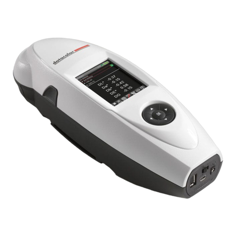
Datacolor CHECK II User manual

Datacolor
Datacolor CHECK II
Quick Start Guide

Datacolor CHECK II Quick Start Guide (October 2008)
User’s Guide Part No. 4230-0401M
Patent Information
Name of originator: Applied Color Systems, Inc.
Date: March 26, 2002
Title of patent document. Portable Color Measuring Device
Patent number: U.S. Patent No. 6,362,886
All efforts have been made to ensure the accuracy of the information
presented in this format. However, should any errors be detected,
Datacolor appreciates your efforts to notify us of these oversights.
Changes are periodically made to this information and are incorporated
into forthcoming versions. Datacolor reserves the right to make
improvements and/or changes in the product(s) and/or program(s)
described in this material at any time.
Copyright © 2008 Datacolor. ALL RIGHTS RESERVED. This material
may not be reproduced or duplicated, in whole or in part, without the
express written permission of Datacolor.
Microsoft® and Microsoft Windows® are registered trademarks of
Microsoft Corporation. All other registered trademarks are the property
of their respective owners.
To obtain information on local agents, contact either of the offices listed below, or
visit our website at www.datacolor.com.
Manufacturer:
Datacolor
5 Princess Road
Lawrenceville, NJ 08648
Phone: 609.924.2189
Web site: www.datacolor.com
Americas (Lawrenceville, NJ)
Telephone:
Fax:
1 (609) 924 2189 / 1 (800) 982 6496
1 (609) 895 7472
Switzerland (Dietlikon)
Telephone:
Fax:
+(41) 1 835 3711
+(41) 1 835 3820
Asia (Hong Kong)
Telephone:
Fax:
+(852) 2420 8283
+(852) 2420 8320

CHECK II Quick Start Guide Contents i
Contents
Contents ..................................................................................i
Datacolor CHECK II................................................................1
Introduction.......................................................................1
Datacolor Portables Desktop Program.......................1
Documentation...........................................................1
Accessories.......................................................................2
Calibration Data.........................................................4
General Information..........................................................4
Operation...................................................................4
Power Source............................................................4
Running from Power Adapter.....................................4
Running from the Internal Battery..............................5
Sleep and Active Mode..............................................6
Replacement Parts ....................................................6
Labels........................................................................6
Safety Warnings ........................................................6
Instrument Maintenance ............................................6
Instrument Controls and Indicators...................................7
Front View..................................................................7
Back View..................................................................7
Measure Button .........................................................7
Instrument Cable...............................................................8
Cable Components....................................................8
Cable Assembly.........................................................9
Cable Connections ..................................................10
Serial Port Connection.............................................11
USB Port Connection...............................................11
Stapler Foot and Aperture Selection...............................12
Dual Aperture Units .................................................12
Stapler Foot Installation...........................................13
Aperture Selection ...................................................14
Interface Features...........................................................16
Display Screen.........................................................16
Persistent Icons.......................................................17
PDA Graffiti Pad and Control Panel.........................19
Control Panel...........................................................20

ii Contents CHECK II Quick Start Guide
Routine Functions................................................................23
Overview.........................................................................23
Instrument Calibration.....................................................23
Calibration Requirements ........................................23
Calibration Procedure..............................................24
Calibration Interval...................................................25
Measuring Samples ........................................................25
Measure Standard/Measure Batch ..........................25
Sample Type............................................................25
Sample Names........................................................26
Storing and Retrieving Samples ..............................27
Performing Color Evaluations .........................................28
Overview..................................................................28
Color Difference Results..........................................29
Other Types of Evaluations......................................29
Evaluation Screen Legend.......................................30

CHECK II Quick Start Guide Introduction 1
Datacolor CHECK II
Introduction
Datacolor CHECK II is a portable spectrophotometer, intended for use
as a device for measuring, specifying and evaluating color in both
laboratory and production settings. It is offered in three different
configurations: Datacolor CHECK II, Datacolor CHECK IIPLUS and
Datacolor CHECK IIPRO, which differ in hardware, software and storage
capacity.
Datacolor CHECK II incorporates a PDA, customized with color
management software, as its interface. It also employs wireless
communications technology to transfer measurement data to desktop
computers.
In addition to its stand-alone functions, Datacolor CHECK II can be
connected, or ―tethered‖ to a Desktop PC to be used as the primary
measuring instrument for other Datacolor programs.
Datacolor Portables Desktop Program
The Datacolor Portables Desktop program is included as part of the
Datacolor CHECK II package. This program is used to transfer or
synchronize data between a stand-alone instrument, and a Datacolor
CHECK II database created on the computer. See Datacolor CHECK II
User’s Guide for detailed information regarding the features and
operation of this program.
Documentation
In addition to this guide, a comprehensive reference manual, Datacolor
CHECK II User’s Guide, is provided as a PDF file on the Datacolor
Portables CD.

2 Accessories CHECK II Quick Start Guide
Accessories
Standard accessories for Datacolor CHECK II include the following:
.
Hex Driver
Spare stylus/
reset tool
Stapler Foot Assembly
See Stapler Foot Installation
for instructions.
Black trap
White
Calibration
Tile
Green
Diagnostic
Tile
White
calibration
Diskette/CD

CHECK II Quick Start Guide Accessories 3
Power Adapter / Power Cord
Communications Cable
(Serial Cable)
(USB Cable)
In addition, you will find a Datacolor CHECK II User Guide, and four
CDs:
Palm® CD. You must install this software to transfer data
between the Datacolor CHECK II and the Datacolor Portables
Desktop software on a Desktop PC.
Datacolor Portables Desktop CD. This contains the
Datacolor Portables Desktop software. You must install this
program to transfer data between the Datacolor CHECK II
™and the Desktop PC.
Instrument Driver CD. Required to use the Datacolor CHECK
II as a measuring device for other Datacolor programs
USB Drivers and Documentation CD. If you will be
connecting the Datacolor CHECK II to a USB port, you must
install this software.

4 General Information CHECK II Quick Start Guide
Calibration Data
If the calibration data is deleted from the instrument, or if you received a
replacement calibration tile, you must install the white tile data. This
requires the data CD. See Datacolor Portables Program, Installing
White Tile Data for detailed instructions to install this data.
WARNING
If you have changed the white calibration tile, you must install the
measurements for the new tile you are using. If you do not, the
instrument calibration and any measurements made are not valid.
General Information
Operation
This product is to be used only in a manner specified by the
manufacturer, and according to the instructions for operation and
maintenance provided herein.
If the equipment is used in a manner not specified by the manufacturer,
the protection provided by the equipment may be impaired.
Power Source
The unit must be used with the power adapter or lithium ion batteries,
provided only by Datacolor.
Power adapter (Datacolor part no. 4050-0065) has a maximum output of
6.5 volts DC, 1.5 amps.
The power cord supplied must be used.
Replaceable lithium ion batteries (Datacolor part. no. 1200-1299) are
the only batteries compatible with Datacolor CHECK II. Do not use any
other rechargeable or non-rechargeable batteries.
The battery is fully charged before it leaves the factory. However, it
may lose some of its charge by the time it arrives at your location.
Connect the Datacolor CHECK II to the power adapter as soon as
you receive the unit. See “Instrument Cable” for instructions on how to
attach the power adapter to the unit.
Running from Power Adapter
Whenever Datacolor CHECK II is connected to the power adapter, it
automatically recharges the battery at the same time it is providing
power to the unit. You can make measurements while the battery is
recharging. When the battery is totally discharged, it takes
approximately 4 hours to fully recharge it.

CHECK II Quick Start Guide General Information 5
NOTES
When you connect the unit to the external power adapter, the
instrument will not recharge if the instrument is asleep (the LED
indicator on the front is not lighted). Press the Measure button on the
back of the unit to activate the instrument.
The instrument will never enter Sleep mode while it is connected to the
external adapter. The PDA will time out, but the instrument will remain
active (the LED indicator on the front of the unit will be lighted).
Running from the Internal Battery
When the battery icon contains a single bar, the battery level is low, and
a text message displays, prompting you to charge the battery.
When the remaining power drops to a critical level, a second ―low
battery warning‖ displays, and the battery icon will not contain any bars.
When this message displays you have battery power remaining for
approximately 30 measurements. BACK UP your data NOW, if you
have not already done so. If you do not, you will not have enough
power to complete the backup process.
When the LED indicator on the front of the unit repeatedly cycles
through the green/red/amber color sequences the unit is ready to shut
down. You DO NOT have enough power to complete a backup. You
should immediately connect the unit to the external power adapter.
WARNINGS
When the battery is totally discharged, everything on the PDA
interface is lost!!! Back up your data regularly to the flash memory
card so that you do not lose any important information.
If the LED indicator remains amber or red for an extended period of
time, the instrument needs to be reset. To reset, press the Measure
button on the back of the unit until the light goes out. You can then
resume using the instrument.

6 General Information CHECK II Quick Start Guide
Sleep and Active Mode
To conserve the internal battery power, both the instrument and the
PDA are programmed to timeout, or go into Sleep mode when no
activity is detected over a specified time period.
The Sleep function is controlled separately for each component. As a
result, the instrument can remain active (―awake‖) while the PDA is
asleep, and the PDA can remain active (―awake‖) while the instrument is
asleep.
Replacement Parts
This instrument uses high voltage during operation, and should only be
serviced by qualified personnel.
Labels
There are several labels on the unit including the following.
The WARNING symbol indicates that the user should refer to the
documentation before using the instrument.
Datacolor CHECK II instrument model and serial number.
Safety Warnings
Light Source. Do not stare directly into the open port located at the
bottom of the instrument, when a measurement is in progress. Staring
directly into the light source can result in eye discomfort similar to that of
staring at a camera flash.
CAUTIONS
(1) Disconnect all power before servicing.
(2) The power cord supplied must be used.
(3) There are no user serviceable parts for this system.
Instrument Maintenance
There are no user-serviceable parts for this equipment.

CHECK II Quick Start Guide Instrument Controls and Indicators 7
Instrument Controls and Indicators
Front View
Back View
Measure Button
When you press the RED Measure button on the back of the unit (see
above photo) the instrument automatically makes a measurement
without prompting you for any information.
Power Button
Flash Memory
Card Slot
Recessed Screw
(Remove for Battery Replacement)
Serial Port
Strap Attachment
Strap Attachment
Aperture Switch
Measure Button
Stapler Foot
Locking Key
Stapler Foot
Power Adapter
Status
PDA Interface
Graffiti Pad
Control Panel
Thumb Recess
LED Indicator
Stapler Foot

8 Instrument Cable CHECK II Quick Start Guide
Instrument Cable
A custom cable is included with the instrument. This cable comes as 3
separate components that you must assemble.
It is used for two functions:
To connect the Datacolor CHECK II ™to its power adapter.
To connect Datacolor CHECK II to a port on a PC.
Cable Components
When assembled, the Datacolor CHECK II cable has 3 connectors on it.
One connects to the instrument, one connects to a port on the
computer, and one connects to the power adapter.
NOTE
Two communications cables are supplied with the instrument.
One is used to connect the unit to a serial port, and the other is used to
connect to a USB port. You will only use one of these cables, based
on the type of communications port available on your computer.
Serial
Communications Cable
USB
Communications Cable
NOTE
If you will not be using the Datacolor CHECK II with other Datacolor
software programs, you can use either communications cable.
8-pin radial
connector (to
back of
instrument)
coaxial cable
(to power adapter)
Connector to
port on
computer

CHECK II Quick Start Guide Instrument Cable 9
Power Adapter. This component includes a coaxial connector, and a
power adapter with power cord receptacle.
Power Adapter Cord. Includes plugs to power outlet and to power
adapter.
CAUTION
The power cord supplied with the unit must be used.
Cable Assembly
WARNING
Disconnect the power adapter from the wall outlet before connecting
Datacolor CHECK II to the adapter or PC.
1. Plug the coaxial connector from the Datacolor CHECK II
connector (1) into the coaxial connector from the power
adapter (1).
2. Insert the adapter power cord into the adapter (2).
3. Plug the radial connector (3) into the port on the back of
the Datacolor CHECK II.
When assembled correctly, your cable should look like the diagram
below:
Coaxial
connector
Power cord
receptacle
Power outlet
Power adapter plug
1
2
3

10 Instrument Cable CHECK II Quick Start Guide
Cable Connections
DC adapter (1)
Connector to instrument (2)
Connector to port on PC (3)
The 8-pin radial connector (2) plugs into the port on the back of the
instrument. The USB/Serial connector (3) connects to a port on a
computer.
Serial Port Cables
The serial D connector is used to connect to the serial port on a
computer.
LEFT. 8-pin Serial D Connector
(to serial port on computer)
RIGHT. 8-pin Radial Connector
(to back of unit)
Back of Datacolor CHECK II
USB Port Cables
The USB connector is used to connect to a USB port on the back of the
computer.
LEFT. USB Connector
(to USB port on computer)
RIGHT. 8-pin Radial Connector
(to back of Datacolor CHECK II)
Back view of
Datacolor CHECK II
1
3
1
2
1

CHECK II Quick Start Guide Instrument Cable 11
NOTE
To use Datacolor CHECK II with a USB port, you must install software
onto the system. For instructions to install the USB drivers, see
Datacolor CHECK II User’s Guide
Connecting the Instrument to the Power Adapter
The cable must be completely assembled in order to run Datacolor
CHECK II from the power adapter.
1. Insert the 8-pin radial connector into the port on the back
of the instrument. Looking at the rear of the instrument,
the flat edge of the connector shield faces to the right.
2. Plug the power cord into an outlet.
Connecting the Instrument to a Desktop PC
The Datacolor CHECK II can be connected to a desktop PC for use as
the measuring instrument for other Datacolor programs, and for data
synchronization.
For use as a color measuring device, you must connect the
instrument using a cable, to either a serial or USB port.
For data synchronization, you can use either a wired or
wireless connection. If you use a wired connection, you can
use either a serial or USB port. See Datacolor CHECK II
User’s Guide to configure the unit and perform this data
transfer.
Serial Port Connection
1. Insert the radial connector into the port on the back of the
Datacolor CHECK II. Looking at the rear of the
instrument, the flat edge of the connector shield faces to
the right.
2. Insert the serial D connector into the serial port on the
back of the computer.
USB Port Connection
You must install software to allow communication between the
Datacolor CHECK II and the USB port. See Datacolor CHECK II User’s
Guide for USB software installation instructions.
1. Insert the radial connector into the port on the back of the
instrument. Looking at the rear of the instrument, the flat
edge of the connector shield faces to the right.
2. Insert the USB connector into the USB port on the back of
the computer.

12 Stapler Foot and Aperture Selection CHECK II Quick Start Guide
Stapler Foot and Aperture Selection
Dual Aperture Units
There are three possible aperture sizes available on Datacolor CHECK
II. A dual aperture unit includes any two of the selections listed below:
Aperture
Selection
Aperture
Plate at Port
Switch
Identification
Stapler Foot
Assembly ID
Large Area View
LAV
L
LAV
Small Area View
LAV
S
SAV
Ultra-Small Area View
LAV
U
USAV
Extra-Ultra Small
Area View*
LAV
U
XUSAV
*Extra-Ultra Small Area View uses the same switch position as Ultra-Small
Area View. The only difference is the size of the viewing area targeted by the
stapler foot for XUSAV. The switch position used is U (Ultra-Small Area
View), and the stapler foot used is XUSAV.
Dual aperture instruments have an aperture switch on the back of the
unit.
If you have a single (fixed) aperture unit, there is no aperture switch on
the back.
The stapler foot is attached to the bottom of the unit.
It is used to target the area measured. The aperture
size is clearly identified on the stapler foot, and
should always match the aperture switch setting you
are using.
Aperture Switch

CHECK II Quick Start Guide Stapler Foot and Aperture Selection 13
Stapler Foot Installation
A stapler foot assembly is provided for each aperture. This is attached
to the bottom of the unit.
WARNING
Exercise caution when installing the stapler foot.
Below are pictures of the stapler foot assembly and the bottom of the
unit where it is installed.
Bottom of Unit
Stapler Foot Assembly
To install the stapler foot, do the following:
1. Slide the locking key on the
stapler foot to the right to close
it.
2. Orient the stapler foot assembly
so that the front of the stapler
foot assembly is parallel to the
front of the unit.
3. Align the red dot on the stapler
foot with the gray dot on the
instrument.
Locking Key
Slides left/right to lock/
unlock jaw of stapler foot.
Aperture ID. The aperture size
is clearly identified on the stapler
foot
Red Dot (not shown)
Used to align foot with instrument
during installation.
Sphere Opening

14 Stapler Foot and Aperture Selection CHECK II Quick Start Guide
4. Turn the stapler foot clockwise to lock it into position. The
red dot on the stapler foot will line up with the red dot on
the instrument.
5. To remove the stapler foot from the unit, turn the stapler
foot counterclockwise.
6. Turn the aperture switch to the selection that matches the
stapler foot installed on the unit.
Aperture Selection
1. Install the stapler foot assembly, using the instructions in
this guide.
2. Dual aperture units are fitted with a silver switch on the
back of the unit.
Aperture
Position
Indicator

CHECK II Quick Start Guide Stapler Foot and Aperture Selection 15
3. Turn the switch to the position that matches the stapler
foot aperture size.
4. Calibrate the instrument. Following calibration, the
aperture icon on the PDA screen should match the switch
position on the back of the unit, and the aperture
identification on the stapler foot assembly.
Aperture Setting
Small Area View
Large Area View
Ultra-Small Area View
NOTE
When you change the aperture selection, the aperture
icon on the display is not updated until you make a
measurement.

16 Interface Features CHECK II Quick Start Guide
Interface Features
Below is the Datacolor CHECK II user interface. It is composed of three
sections:
Touch Screen
Graffiti Pad
Control Pad
Datacolor CHECK II utilizes many standard PDA navigation
conventions. Some of these functions have been customized to
accommodate features specific to Datacolor CHECK II.
Display Screen
Table of contents
Other Datacolor Measuring Instrument manuals

Datacolor
Datacolor 200 User manual

Datacolor
Datacolor ELREPHO User manual

Datacolor
Datacolor SpyderTV User manual

Datacolor
Datacolor Elrepho 3000 User manual

Datacolor
Datacolor 800 User manual

Datacolor
Datacolor SpyderPRINT User manual

Datacolor
Datacolor ColorReader EZ User manual

Datacolor
Datacolor ColorReaderPRO DC10-1 User manual

Datacolor
Datacolor 20D User manual

Datacolor
Datacolor 45 User manual