SPECTRO SPECTROLAB User manual

DasverknüpfteBildk ann nichtangezeigtwerden.Möglicherweisewurdedie Dateiverschoben, umbenanntoder gelöscht.StellenSie sicher, dass d ie Verkn üpfung aufd ie
korrek teD ateiu nd den ko rrekten Sp eicheror tzeig t.
SPECTROLAB
Stationary metal analyzer
Original operating instructions


SPECTROLAB — 30.07.2015 — 3
Table of Contents
1Description of instrument....................................................................................5
1.1Description.......................................................................................................................... 5
1.2Function.............................................................................................................................. 5
1.3Overview............................................................................................................................. 6
1.3.1Instrument (front)................................................................................................... 6
1.3.2Instrument (back)................................................................................................... 7
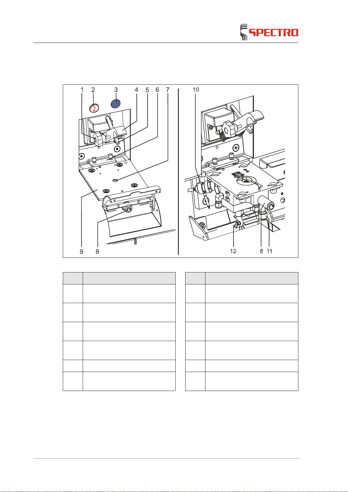
1.3.3Spark stand ........................................................................................................... 8
2Safety..................................................................................................................9
2.1Symbols used ..................................................................................................................... 9
2.2User information................................................................................................................ 10
2.3Intended use..................................................................................................................... 11
2.4Prohibited operating conditions ........................................................................................ 11
2.5Residual risks.................................................................................................................... 11
3Technical data...................................................................................................14
4Transportation/Setting-up .................................................................................15
4.1Space requirements.......................................................................................................... 16
4.2Storage ............................................................................................................................. 16
4.3Gas supply........................................................................................................................ 17
5Initial start-up ....................................................................................................18
5.1Preparing the instrument for use ...................................................................................... 18
6Operation..........................................................................................................19
6.1Overview of controls ......................................................................................................... 19
6.2Switching on the instrument.............................................................................................. 20
6.2.1Argon saving module........................................................................................... 20
6.3Switching offthe instrument............................................................................................... 21
6.4Measuring procedure........................................................................................................ 22
6.4.1Preparing the measuring procedure.................................................................... 23
Re-profiling the optics and standardizing the instrument (only LAVM12)........... 23
Re-profiling the optics.......................................................................................... 23
Standardizing the measuring device (only LAVM12).......................................... 24
iCALising the measuring device (iCAL) (only LACM12)...................................... 24
Changing the base (multi-base instruments only)............................................... 24
6.4.2Proceed with the measurement........................................................................... 25
7Maintenance .....................................................................................................26
7.1Maintenance schedule...................................................................................................... 26
7.2Maintenance Reminder..................................................................................................... 26
7.3General Maintenance........................................................................................................ 27
7.4Clean the light inlet window of the optics (MgF2)............................................................. 28

— 4 SPECTROLAB — 30.07.2015
7.5Clean the light inlet window of the optional air optics (LAVM12)......................................29
7.6Cleaning the spark stand ..................................................................................................31
7.7Clean exhaust hose ..........................................................................................................33
7.8Changing the electrode.....................................................................................................35
7.9Replacing the standardizing or re-profiling samples (LAVM12)........................................37
7.10Replacing the iCALization sample (LACM12....................................................................37
7.11Replacing the filters...........................................................................................................38
7.11.1Replacing the insert of the filter bottle.................................................................39
7.11.2Inspecting the gas-washing bottle .......................................................................40
7.11.3Replacing the filter mats......................................................................................41
8Status messages..............................................................................................42
9Troubleshooting................................................................................................ 43
9.1Error messages.................................................................................................................45
9.2Diagnosis tool....................................................................................................................45
10Spare parts and consumables..........................................................................46
11Pos: De-commissioning....................................................................................46

Description of instrument
SPECTROLAB — 30.07.2015 — 5
1 Description of instrument
1.1 Description
Designation: SPECTROLAB SPECTROLAB
Model: LAVM12 LACM12
Type: 76004140 76004141
1.2 Function
Sample material is evaporated by spark discharge inside the unit. In this process,
the released atoms and ions are excited and emit light. This light is directed into
the optical systems and measured using sensors.
Calibration data are already stored in the unit's memory. The measured values are
compared with these data. The measured values are converted into
concentrations and then displayed on the screen.

Description of instrument
— 6 SPECTROLAB — 30.07.2015
1.3 Overview
1.3.1 Instrument (front)
Fig. 1
No. Component No. Component
1 Sample clamp 6 Status display of spark discharge
(Plasma generator)
2 Filter mat electronic room 7 Filter mat spark discharge
(Plasma generator)
3 Unlocking mechanism for
protective cover 8 Door opener (access to gas-
washing bottle and filter bottle)
4 Filter mat for cooling system 9 Gas-washing bottle and filter
bottle (inside instrument)
5 On/Off switch
Spark discharge (Plasma
generator)
10 Access to spacer

Description of instrument
SPECTROLAB — 30.07.2015 — 7
1.3.2 Instrument (back)
Fig. 2
No. Component No. Component
1 Argon connection 3 Electronic unit with fuse
2 PC data transmission connection

Description of instrument
— 8 SPECTROLAB — 30.07.2015
1.3.3 Spark stand
Fig. 3
No. Component No. Component
1 Locking wheel for contact 7 Electrode and spark stand insert
(below the spark stand plate)
2 On/Off switch for spark discharge
(Plasma generator) 8 Spacer
3 Status display of spark discharge
(Plasma generator) 9 Sparky stand plate
4 Clamp (swinging) 10 Optical fibre for air optical system
(only for LAVM12)
5 Contact (movable) 11 Outlet to filter system
6 Replaceable window (in the light
channel to the optical system) 12 Electrode holder

Safety
SPECTROLAB — 30.07.2015 — 9
2 Safety
Every user of the instrument must have understood these operating instructions.
This applies in particular to the safety regulations.
2.1 Symbols used
The following symbols are used in these abbreviated operating instructions and on
the instrument.
If required, additional important information is available in connection with these
symbols.
Caution! Risk of injury!
Caution! Risk of electric shock!
Caution! Risk of burns!
Caution! Danger of poisoning!
Caution! UV radiation!
Notice!
Warns of activities or conditions that may adversely affect the
safety or function of the instrument.
Note
Displays information that is important for the correct and safe use
of the instrument

Safety
— 10 SPECTROLAB — 30.07.2015
2.2 User information
Caution! Risk of injury and health hazard!
Non-compliance with the operating and safety instructions may lead to injuries
and can cause a health hazard.
Carefully read the manual and always comply with the safety instructions.
The instrument - in its transport packaging - may only be transported by
expert organizations or by specifically trained personnel.
If an instrument is positioned on a sloped surface and equipped with wheels, it
may roll away during the operation. Secure the instrument while in operation.
This applies also when the instrument is being transported.
Unpacking, installation, setup and connection of the instrument may only be
performed by service personnel that is authorized by the manufacturer.
The instrument may only be connected to the mains power supply with a
protective grounding conductor.
The instrument may be operated only in a dry environment (protection class
IP 22, DIN 40050).
Prior to opening the instrument, disconnect the power. The instrument is only
completely disconnected from power if the power plug is removed.
Never tamper with the safety devices! If it is suspected that a safety device
does not work properly, shut down the instrument immediately. Please contact
your Service Center.
Compliance with the information labels on the instrument is mandatory.
While operating and maintaining the instrument, compliance with all safety
and accident prevention regulations is mandatory. This is specified in DIN EN
61010 or a comparable national standard.
Compliance with the relevant safety regulations when using tools and
operating equipment is mandatory.
Carry out only the maintenance work that is described in chapter "" of the
instruction manual. The operating personnel is not permitted to proceed with
any other maintenance work. Any further services (e.g. technical
maintenance) or repairs must only be performed by service personnel that are
authorized by the manufacturer.
The safety measures must be checked following every technical maintenance
or repair activity. This check must be performed according to VBG4/DIN EN
61010 or a comparable national standard.
Compliance with the maintenance schedule specified by the manufacturer is
mandatory, All maintenance activities must be recorded. This will maintain the
operational safety of the instrument.
Only genuine spare parts must be used when repairing the instrument. The
use of non-genuine spare parts will make the CE Declaration of Conformity
null and void.

Safety
SPECTROLAB — 30.07.2015 — 11
2.3 Intended use
This instrument analyzes and identifies metals. Only such metals may be analyzed
for which the instrument has been calibrated by the manufacturer or by qualified
technical personnel.
2.4 Prohibited operating conditions
Do not operate the instrument if one of the following conditions exists:
If the instrument is faulty or damaged.
If the instrument is not maintained at regular intervals.
If the ambient conditions do not comply with the specification.
If the area where the instrument is used is not a commercial/industrial
premise.
2.5 Residual risks
This instrument has been manufactured in accordance the latest state-of-the-art
technology. Nevertheless, a residual risk cannot be completely excluded.
Caution! Risk of injury and health hazard!
The light inlet window of the optional air optics is located below the spark
stand. When removing the light inlet window, mechanical parts in this area
may cause injuries.
Protective gloves must be worn.
The instrument is operated with argon. Argon is heavier than air. It can
accumulate in a closed room, especially on the floor or lower-lying areas.
Ensure to provide adequate ventilation. If necessary, install oxygen
sensors.

Safety
— 12 SPECTROLAB — 30.07.2015
Caution! Toxic!
The sparking process produces a black precipitate (metal condensate). The
condensate could be toxic or flammable, depending on the sample material.
Protective gloves and safety goggles must always be worn when
cleaning in the spark stand and when cleaning the gas-washing bottle
the filter bottle. This also applies when replacing the filter insert.
When disposing of the condensate, compliance with legal regulations is
mandatory.
Metal vapors may be generated from the sample material. Depending on the
sample material, these vapors may be toxic, e.g. in case of heavy metals.
Ensure that protective equipment is worn in such cases, e.g. a
breathing apparatus and extraction equipment is installed. The
protective methods must ensure that the applicable threshold limit
values (TLV) and/or comparable national standards are not exceeded.
Caution! Risk of electrical shock!
When the instrument is switched on, there is a risk of an electric shock when
the electrode is touched or when the sample is removed during a
measurement.
Never touch the sample while a measurement is in progress.
Avoid any contact with the electrode when the instrument is switched
on.
Shut down the source (plasma generator) during all work on the spark
stand.
For voltage ranges, see page 13.
Caution! Risk of burns!
Contacting the electrode increases the risk of burn injuries. During normal
operation, the electrode will heat up to several hundred degrees.
Never touch the electrode with your bare hands, even after shutting
down the spectrometer. Always use pliers.
A sample can get hot if it is measured several times.
Touch the sample only after is has sufficiently cooled.

Safety
SPECTROLAB — 30.07.2015 — 13
Caution! Fire hazard!
The sparking process produces a black precipitate (metal condensate). The
condensate could be toxic or flammable, depending on the sample material.
Protective gloves and safety goggles must always be worn when
cleaning in the spark stand and when cleaning the gas-washing bottle
the filter bottle. This also applies when replacing the filter insert.
When disposing of the condensate, compliance with legal regulations
and fire prevention instructions is mandatory.
Caution! UV radiation!
The arc on the spark stand generates UV radiation.
Use the appropriate sample adapter for samples that are not completely
covered by the spark stand opening.
Take appropriate protective measures (e.g. wear safety goggles) when
the spark stand opening is not fully covered.
Note
A high-voltage pulse ignites the plasma.
After the ignition, an alternating voltage (spark mode) or a direct voltage (arc
mode) is applied to the electrode.
The following table shows the respective voltage ranges.
The cooling system contains a coolant. The associated safety data sheet is
available at http://MSDS.spectro.com.
Content of gas cleaning cartridge: The associated safety data sheet is available
at http://MSDS.spectro.com.
High-voltage ignition pulse,
Spark mode Burning voltage
Spark mode
SPECTROLAB
(LAVM12/LACM12) 1 – 12 kV, type 5 kV 30 – 240 V, type 50 V

Technical data
— 14 SPECTROLAB — 30.07.2015
3 Technical data
Description Value
Instrument height 1405 mm; 55.3"
Instrument width 770 mm; 30.3"
Instrument depth 1900 mm; 74.8"
Instrument weight approx. 500 kg; ~ 1102 lbs
Power supply 198 - 253 VAC, 50/60 Hz
Power during measurement 1.0 kVA
Power during stand-by 0.5 kVA
Fuse 16 A (slow-blow)
Operating range (permissible
ambient temperature) 15°C – 30°C; 59°F – 86°F
Recommended temperature range
for reaching the specified
performance
18 – 30°C; 64 – 86°F
Operation Unless specified differently in the order, 2,500 m
max. above mean sea level.
Air humidity range 20 – 80%, not condensing
Pollution index 1
Sound pressure level 55 dB(A)
Stability (according to DIN EN
61010-1) compliant if change of position <10°
Argon inlet pressure on the
instrument 5.0 bar
Argon quality (min.) 4.8 (99.998% Ar) mit O2<3ppm, N2<10ppm,
H2O<5ppm, kV<1ppm
When analysing for nitrogen/oxygen:
Argon > 99.999% with O2<0.5ppm, N2<0.5ppm;
H2O<3ppm, KW<1ppm
Argon flow rates Spark stand flushing
Stand-by (low flow)
5 L/h (LACM12)
Constant flow 30 L/h
Analytic flow 230 L/h (LAVM12)
140 L/h (LACM12)
Storage conditions Ambient temperature
-15 – 45°C; 5 – 113°F

Transportation/Setting-up
SPECTROLAB — 30.07.2015 — 15
4 Transportation/Setting-up
Notice! Risk of damage to the instrument and other property!
Improper transport may cause damage to the instrument or to other property within
the surroundings.
Only specifically trained personnel shall be permitted to transport the
instrument in its transport packaging.
If the usage site must be changed, please contact our service
department.
Consider the dimensions and the weight of the instrument.
Ensure that the transportation route is free of obstacles and bottlenecks
are avoided.
Since the instrument weighs approx. 500 kg, the structural properties of
the transportation route and the load capacity of the place of installation
must be considered.
Unpacking, installation, setup and connection of the instrument may only be
performed by service personnel that is authorized by the manufacturer.
Note! Risk of measuring errors!
If the instrument is subject to vibrations and shocks, measurement errors
may occur during the measuring process.
The instrument must be installed in a vibration- and shock-free location.
Measurement errors result from temperature differences inside the
instrument.
The instrument must be installed at a location, where it cannot heat up
or cool down on one side only.
The instrument may be operated only in a dry environment (protection class
IP 22, DIN 40050).
Observe the following information regarding the instrument's installation:
All connections are located at the back panel.
The instrument must be accessible from all sides for maintenance. Set up the
instrument accordingly. Sufficient space should be provided for the computer
workstation (keyboard, monitor, printer) and the operating personnel.
The clearance from other objects must be at least 60 cm (including the rear).
In addition to the space required by the instrument, some space is needed for
the gas supply, unless fixed gas connections are available.

Transportation/Setting-up
— 16 SPECTROLAB — 30.07.2015
4.1 Space requirements
4.2 Storage
Storage conditions:
The instrument must be stored in a dry place
Room temperature -15°C – +45°C (5°F – 113°F)
Avoid storing the instrument at very low temperatures.

Transportation/Setting-up
SPECTROLAB — 30.07.2015 — 17
4.3 Gas supply
Note! Risk of measuring errors!
Impurities in the argon supply cause measuring errors.
Ensure oil and grease-free laying of the argon supply line.
The spectrometer requires an argon supply line.
A suitable pressure reducer is required for the argon supply (bottles or liquid gas
tank).
Adjustable output pressure 0 – 10 bar
The argon inlet pressure at the instrument is 5 bar (72 psi)
A copper tube for the argon supply is provided with the delivery of the SPECTRO:
Diameter 6 x 1 mm, length 3 m
When using longer lines and/or smaller tube diameters, a possible
pressure drop must be taken into account.
This line is screwed to the connection on the rear panel of the instrument. The
threaded connection is included in the scope of supply.

Initial start-up
— 18 SPECTROLAB — 30.07.2015
5 Initial start-up
5.1 Preparing the instrument for use
Before switching on the instrument, proceed as follows:
1. Check if the mains voltage selector switch of the PC is set to the proper input
voltage (230V/115V).
2. Check the filling level of the gas-washing bottle. Fill with water if required, see
page 40.
3. Set the argon pressure to 5.0 bar (72 psi).
If the argon pressure is not properly set, turbulences result in the spark
stand insert. Thus, correct measuring results cannot be obtained.
The instrument is ready for use.

Operation
— 20 SPECTROLAB — 30.07.2015
6.2 Switching on the instrument
Note
To operate the instrument in compliance with the specification, it should be
stabilized after switching it on. After reaching the optical system's target
temperature (20°C, 68°F), the system may require at least two hours to stabilize.
To switch on the instrument, proceed as follows:
1. Connect the instrument to the power supply.
2. In order to switch on the Plasma generator, press the following buttons:
3. Switch on the computer.
The operating system is started.
4. After booting the operating system, start the "Spark Analyzer Pro"
spectrometer software.
The instrument is switched on.
6.2.1 Argon saving module
The argon flow is deactivated by switching off the Plasma generator. This
minimizes the overall argon consumption.
For restoring the readiness for measurements, flushing with the analytic flow is
carried out.
When the argon flow is automatically activated again is determined in the "Argon
saving module" screen dialog. Immediately thereafter, the instrument is ready for
operation.
For a detailed description, refer to the online Help of the instrument.
This manual suits for next models
2
Table of contents
Other SPECTRO Measuring Instrument manuals
Popular Measuring Instrument manuals by other brands

Bender
Bender LINETRAXX RCMS150 quick start guide

Trace2O
Trace2O METALYSER DELUXE HM2000 quick start guide

Vectornav
Vectornav VN-100 user manual

Lutron Electronics
Lutron Electronics PDO-519 Operation manual

McCrometer
McCrometer FPI Mag 394L quick start guide

Sper scientific
Sper scientific 840080 instruction manual

Ludlum Measurements
Ludlum Measurements 43-5 manual

Bante Instruments
Bante Instruments Bante221 instruction manual

Beko
Beko FLM SF53 Installation and operation instruction

Pfeiffer Vacuum
Pfeiffer Vacuum GAUGE/IO Supplementary information

Elcometer
Elcometer 345 operating instructions

Bender
Bender LINETRAXX RCM410R-24/-2 manual