Sentek SD119 Series Quick start guide

Photoelectric
Smoke Detector SD119 series
Installation Wiring Diagram
TYPICAL WIRING DIAGRAM
Figure 1.a shows the typical wiring diagram of 2-wire
multiple-station smoke detector system.
DO NOT USE LOOPED WIRE UNDER
TERMINALS 2 AND 5 BREAK WIRE RUN TO
PROVIDE SUPERVISION OF CONNECTIONS
Figure 1.b shows the typical wiring diagram of 4-wire
multiple-station smoke detector system.
DO NOT USE LOOPED WIRE UNDER
TERMINALS 2 AND 5 BREAK WIRE RUN TO
PROVIDE SUPERVISION OF CONNECTIONS
WARNING
TO PREVENT DETECTOR CONTAMINATION
AND SUBSEQUENT WARRANTY
CANCELL-TION, SMOKE DETECTOR MUST
REMAIN COVERED UNTIL AREA IS CLEAN
AND DUST FREE.
INSTALLING THE BASE
1. To insure proper installation of the detector head to the
base, all the wires should be properly addressed at
installation:
(A)Position all the wires flat against terminals.
(B)Fasten the wires away from connector terminals.
2. If you use the jumper wire to connect the poles of
terminal 2 and 5 when testing the detector loop
continuity, be sure to remove the jumper wire prior to
the installation of the detector head.
3. The end-of-line device shown in Figure 1.a & 1.b
should be compatible with the control unit. The
end-of-line supervisory relay used should list the rated
DC power voltage used.
4. Per UL listing, open area smoke detectors are
intended for mounting on a ceiling no less than 6
inches from a wall or mounting on a wall than no less
than 4 inches and no more than 12 inches from a
ceiling.
5. The base of smoke detector can be mounted directly
onto electrical junction box such as octagonal (3”, 3.5”
or 4”), round (3”), and square (4” length) box without
using any type of mechanical adapter.
INSTALLING THE HEAD
1. Align the components as shown in Figure 2.
2. Mate the detector head onto the base and twist
clockwise to secure it.
3.Do not install the detector head until the area is
thoroughly cleaned of construction debris, dusts, etc.
The maximum number of smoke detector installed in
the same loop is 30 units.
Fig. 2 Mating detector head onto base
ADJUSTMENT OF THE RELAY POSITION
4-wire type: Adjust the relay set-position for wiring unit to
the security monitoring system by the following steps:
1. The reset position for the relays is at “normal open”
(NO) position, when energizing all the relays.
2. If one needs to adjust the relay set point, use a
screwdriver to loose two screws on the back of the
base. See Figure 3, there is a jump head next to the
relay on the PCB, adjust it to select set point either
“normal close” (NC) or “normal open” (NO) position.
3. Relay contact rating:
1A @30VDC,
0.5A @125VAC.
TESTING
1.All the alarm signal services, releasing device and
extinguisher system should be disengaged during the
test period and must be re-engaged immediately at the
conclusion of testing.
2.After energizing the detector head for approximately
one minute, check to see the indicator red LED
flashing once every 1~3 seconds. If red LED fails to
flash, it indicates the non-functioning of the detector or
faulty wiring. Re-check the wiring or replace the
detector if necessary.
Fig. 3 Schematic of detector structure
Whenfrontcoverisopen
3. Allow smoke from a cotton wick or a punk to enter the
detector’s sensing chamber for at least 10 seconds.
When sufficient smoke has entered the chamber, an
alarm signal will take place by indicating with a
continuous illumination of the LED. After it alarms,
Reset each detector and/or control unit before
attempting to test the additional detectors in the same
zone. If the alarm fails in this step, it indicates a
defective unit, which requires service.
HEAT SENSOR TESTING
The detector to be tested should be subject to a flow of
warm air at a temperature between 140 and 180 .℉℉
Some domestic hair dryers can meet such requirement.
Proceed as follows:
1. Switch on the warm airflow and check that temperature
is correct and stable.
2. From a distance of inches, direct the airflow at the
guard protecting the thermistor. The detector should
alarm within 30 seconds.
3. When alarm is on, immediately remove the heat
source and check that the detector’s red LED is lit.
Reset the detector from the control panel.
4. If the detector fails to go into alarm within 30 seconds it
is too insensitive and needs to be returned to the
distributor for servicing.
5. After testing check that the system is set for normal
operation and notify the appropriate authorities that the
testing operation is complete and the system is active
again.
NOTES FOR USING DETECTOR
The National Fire Protection Association (NFPA)
states that duct smoke detector must not used as a
substitute for open area smoke detector. Duct smoke
detector is solely intended to use in the air handing
equipments for such purposes like dampers or
shutting down the air handing units.
NOT SUITABLE FOR INSTALLATION IN
AREAS WHERE AIR VELOCITIES EXCEED
300 ft/min.
MAINTENANCE
The recommended minimum requirement for detector
maintenance consists of an annual cleaning of dust from
the detector head by using a vacuum cleaner cleaning
program should be agreed to the individual environment
in conformance with NFPA-72A standard.
CAUTION: DO NOT ATTEMPT TO REMOVE THE
SCREWS, WHICH HOLD THE ASSEMBLY OF
SMOKE-SENSING CHAMBER AND PRINTED CIRCUIT
BOARD (PCB). THIS ASSEMBLY IS SEALED FOR
YOUR PROTECTION AND IS NOT INTENDED TO BE
SEPARATED FOR SERVICING BY USERS. OPENING
SUCH ASSEMBLY WILL VOID THE WARRANTY.
REFER TO THE TECHNICAL BULTTIN ISSUE NO.
STSD20080702S01, REV.D, July 02, 2008
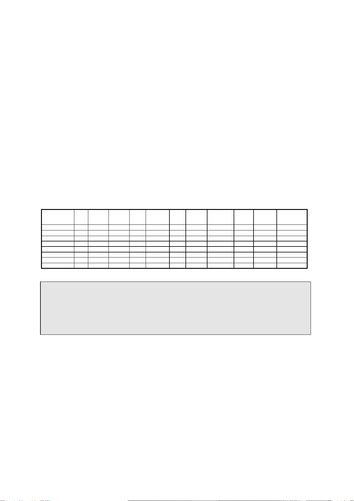
SPECIFICATION
Model 2/4
wire Heat
Sensor
Setting
Voltage
DC
(Min./Max.)
Standby
Current
(Max.)
Alarm
Current
(12/24V)
Surge
Current
(Max.)
Start-Up
Time
(Max.)
Permissible
Current
(Max.)
Cycle
Time Alarm
contact Base
Model No.
SD119-4H(12V) 4 135±5℉12V 80μA 30mA - 30 Sec. - 1-3 Sec. Form A P/N854001
SD119-4H(24V) 4 135±5℉24V 80μA 45mA - 30 Sec. - 1-3 Sec. Form A P/N854001
SD119-4 (12V) 4 - 12V 80μA 30mA - 30 Sec. - 1-3 Sec. Form A P/N854001
SD119-4 (24V) 4 - 24V 80μA 45mA - 30 Sec. - 1-3 Sec. Form A P/N854001
SD119-2HL 2
135±5℉10.8~33V 80μA 22/55mA 160μA 30 Sec. 80mA 1-3 Sec. — P/N854001
SD119-2L 2 - 10.8~33V 80μA 22/55mA 160μA 30 Sec. 80mA 1-3 Sec. — P/N854001
SD119-2H 2
135±5℉10.8~33V 80μA 22/55mA 160μA 30 Sec. 80mA 1-3 Sec. — P/N852001
SD119-2 2 - 10.8~33V 80μA 22/55mA 160μA 30 Sec. 80mA 1-3 Sec. — P/N852001
Remark: L- remote indicator output; H-Heat sensor; AR-Auto-reset; B-Sound
2-wire devices are UL Recognized, the 4-wire devices are UL Listed
LIMITED WARRANTY STATEMENT
SENTEK ELECTRONICS INC. declares that this product is free from defects in material and workmanship. And it will repair
or replace any product or part thereof which proves to be defective in workmanship or material for a period of twelve (12)
months from the date of purchase but not to exceed eighteen (18) months after shipment by the manufacturer. For a full
description of SENTEK’S LIMITED WARRANTY, which, among other things, limits the duration of warranties of
merchantability and fitness for a particular purpose and excludes liability for consequential damages. Please read the entire
LIMITED WARRANTY on the SENTEK quotation. Acceptance of order and/or original invoice which will become part of your
sales agreement. Please contact SENTEK directly for a return merchandise authorization (RMA) number before returning
goods to the factory, Shipment must be prepaid and SENTEK will repair or replace your returned detector.
SDMI119080702, REV C
This manual suits for next models
8
Other Sentek Smoke Alarm manuals


Popular Smoke Alarm manuals by other brands


Teletek electronics
Teletek electronics SensoMAG B12L/U installation manual

System Sensor
System Sensor 6500R Installation and maintenance instructions

COP-USA
COP-USA SDRDVR35 user manual

Honeywell
Honeywell Notifier NBG-12LX quick start guide

Ei Electronics
Ei Electronics Ei 105R Optical product manual

Sygonix
Sygonix SY-5040172 operating instructions