Sentinel CCTV RV56 Guide
5.6”Color Rear View Safety System
Installation & Operation
RV56
(Includes MO56 monitor & CA56 camera)
FOR MORE INFORMATION
WWW.STRATEGICVISTA.COM
BEFORE OPERATING THIS SYSTEM, PLEASE READ THIS MANUAL
THOROUGHLY AND RETAIN IT FOR FUTURE REFERENCE

Before using this unit please read these operating instructionscarefully. Take special
care to follow th warnings indicated on the unit itself as wellas the safety suggestions
listed below. Keep them handy for future reference.
Power source –The unit should be connected to power supply only of the type
described in the operating instructions or as marked on the unit.
Water and Moisture –Do not use this unit near water.
Heat –Do not install the unit near heat sources such as radiators, stoves, heat
registers, or other appliances that produce heat.
Ventilation –The unit should be situated so that its location or position does not
interfere with its proper ventilation.
Foreign material–Care should be taken so that objects do not fall into liquids or not
spilled into the unit.
Surface –Place the unit on a flat, level surface.
Damage Requiring Service-The unit should be serviced by qualified service
personnel when:
-The power cord or the plug has been damaged: or
-Object have fallen or liquid has been spilled into the unit: or
-The unit has been exposed to rain: or
-The unit dos not appear to operate normally or exhibits a marked change
in performance: or
-The unit has been dropped. Or the enclosure damaged.
Replacement Parts –Use only manufacturer specified parts. Unauthorized
substitutions may result in fire, electric shock or other hazards.
Service –The user should not attempt to service the unit beyond that described in
the operating instructions. All other servicing should be refferred to an authorized
service personnel.
Safety Precautions
Warning: This Rear Observation System is to be used with, not instead of, other
viewing aids in your vehicle such as front, rear, and side mirrors. Safe driving
practices, alertness, and visual and physical fitness are prerequisites for your
driving safety. The Manufacturer shall not be held liable for any accidents which
may occur while operating this system.
Caution
!Before making any connections, disconnect the ground
terminal from the battery to avoid a short circuit.
The plugs should be full inserted into the connectors or
jack. A loose connection may cause a malfunction with
the unit
-1-

Table of Contents
-2-
Safety Precautions……………………………………………………….
Introduction………………………………………………………………..
System Contents…………………………………………………………
Features…………………………………………………………………...
Monitor Controls
Front Panel…………………………………………………………
Power Pack Controls………………………….…………………………
Camera Controls…………………………………………………………
Camera Installation………………………………………………………
Monitor Installation……………………………….………………………
Connections………………………………………………………………
Operating Instructions…………………………………………………..
Care & Maintenance…………………………………………………….
Specifications…………………………………………………………….
1
3
3
3
4
5
6
6
8
10
11
11
12

Introduction
Thank you for purchasing the Sentinel 5.6”Color Rear View Safety System. This
system promotes and prevents backing-up and parking accidents by allowing
you to view or check on the traffic behind your vehicle, or when rounding corners
(blind spot prevention).
This system is suitable for waste trucks, RV campers, vans, delivery vehicles &
cars.
To learn more about this system or to find out more about our products available,
please visit our website at:
www.sentinelcctv.com
System Contents
Features
•5.6”Color TFT Monitor
•1/3”CCD Weatherproof Camera
•Power Harness
•65 ft -2 piece camera extension cable
•Sunshield for monitor
•Mounting hardware & bracket for monitor and camera
•Automatic activation of camera when gear is shifted into reverse
•Separate power pack with 3 camera auto-switcher
•Built-in microphone on camera (One-way audio).
•All function electronic control enable (Power, Menu, Volume, CA 1/2/3, Dimmer)
•Normal and Mirror switch for each camera channel
•Waterproof and corrosive proof camera in a compact die-cast housing
•The monitor can be used with a 10V ~ 32V battery with the provided power pack
•Dimmer button to view the image in the night or in a tunnel, etc
•Wide Field of View: 112°Horizontal 84°Vertical 140°Diagonal
•2 piece Waterproof Camera connecting cable (prevents corrosion) with 4 pin Mini
DIN connector
-3-
1
2
3
4
5
6
7
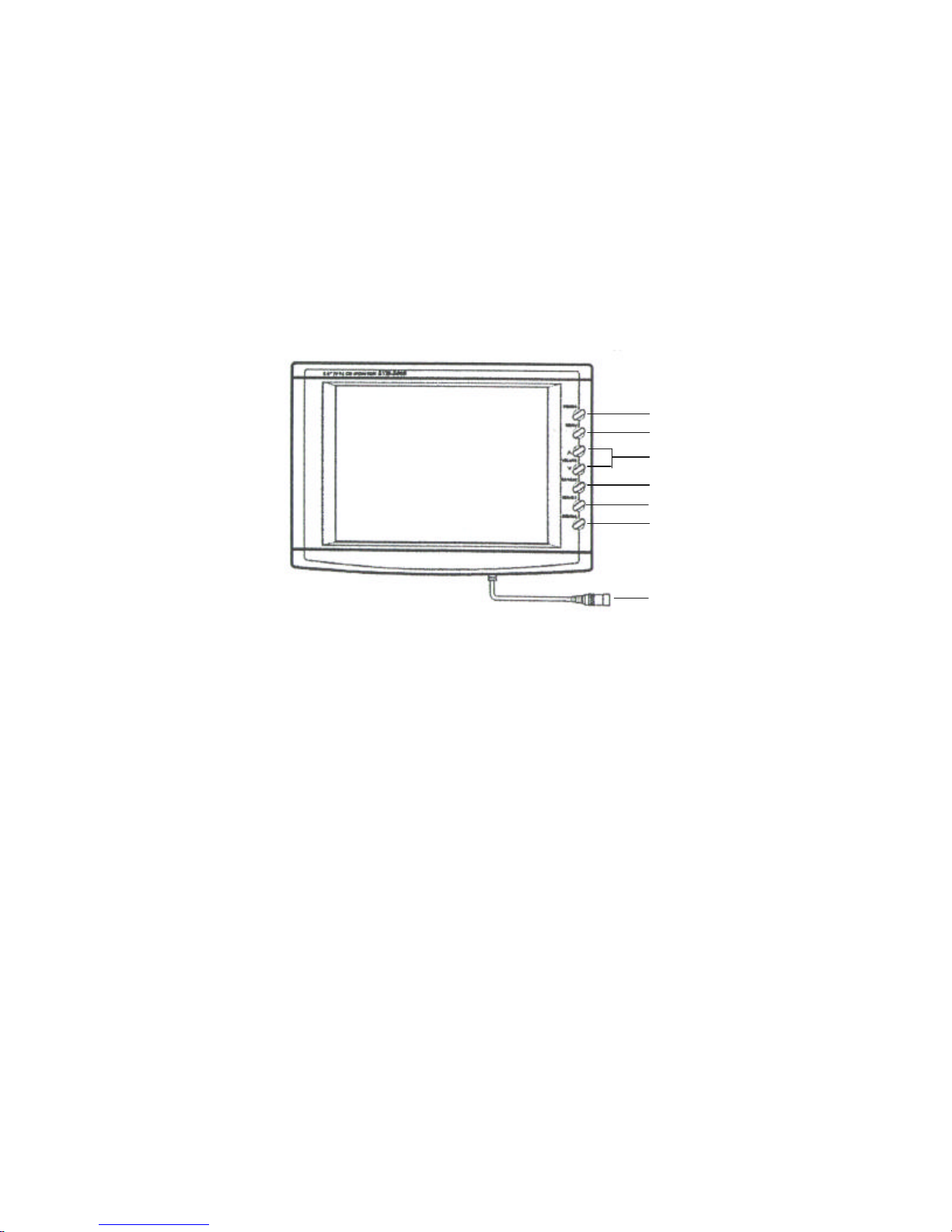
Monitor Controls
Front Panel
1. Power : Power On/Off button
2. Menu : Press the MENU button to go into the programming mode for contrast,
brightness, color and tint
3. Volume ( -VOL + ) : Control the volume up/down or the picture in the MENU
mode
4. CA 1 / CA 2 : Press this button to change from one channel to the other
5. EXT. CAM : (Extra Camera Selector) : Press this button when using a 3rd camera
6. Dimmer : Press to view the picture at night or in a tunnel, etc
7. Monitor Input : Plug this input cable into A/V output on the Power Pack
-4-
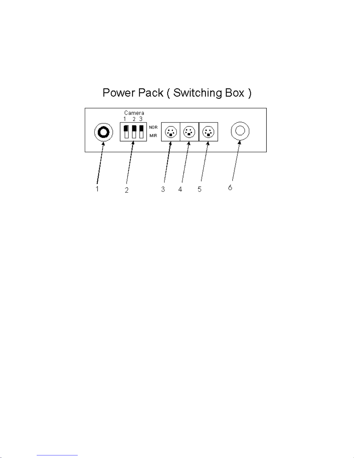
1. Power Input : Power input wires (Green, Black, Red)
2. NOR/MIR Switches: When the switch is in the NOR (Normal) position the
picture for that particular camera is normally displayed. When the switch is in
the MIR (Mirror) position the picture will be reversed (Mirror Image) for that
particular camera
3. CA1 : Camera 1 input (4 pin) -Camera is optional
4. CA2 : Camera 2 input (4 pin) –Camera is optional
5. EXT.CA : To connect to optional camera (4 pin)
6. AV OUT : To connect to monitor
-5-

Camera Controls
Lens
Microphone
Mounting
Bracket
Camera Connector
31
245Ground5
DC 12V power4
Audio3
Video Output2
Not Connected1
DescriptionPin Number
Mount Sunshield over camera using
the 2 screws provided
Camera Installation
1. Connect the 1.8 M cable from the camera to the short 5M piece of the
20M (15M + 5 M) 2-piece extension cable provided.
2. Connect the other end of the 5M cable to the 15M piece, which connects
to CA 1,CA 2 or EXT.CA on the power pack (Switching Box) -6-

1. At the desired camera mounting position, fit the camera mounting bracket
into position using the supplied screws on the center hole and slide hole.
2. Turn the bracket left and right to a correct direction and then tighten the
screws.
3. Fit the camera to the bracket using the supplied washers, spring washers
and screws.
4. Rotate the camera up and down to a position that you can see the picture
you want clearly and then tighten the screws.
5. Drill a cable entry hole through the wall or a door or a window frame just
below the mounting bracket.
6. Pull the cable fully through the hole. Inside the protected property, attach
the extension cable to the cable from the camera. Run the extension
cable to the monitor position. Then shield the hole that you made.
IMPORTANT : Do not connect any camera to
the monitor while the monitor is switched on.
Camera Installation
-7-

Monitor Installation
•Install the monitor on a surface which will support more than 1.8 kg (4
lbs) of weight
•Do not install the unit in an extremely hot or humid place (radiator, air
duct, etc) or in a place subject to direct sunlight, excessive dust,
mechanical vibration or shock
•The monitor is not designed for outdoor installation
1. Before installing this monitor clean it with alcohol
2. Slide the Fix knob (located on the fan shaped bracket) onto the L-
shaped bracket
3. Screw the combined bracket onto the monitor. The thread for the
monitor is located at the bottom
4. Peel off the adhesive tape on the fan shaped base. Using the 4 self
tapping screws, screw the fan shaped base onto a flat surface in the
vehicle
5.Adjust the angle and direction for proper viewing on the monitor
6. Connect the wires accordingly
-8-

Back of TFT Monitor
Assembled Monitor Bracket
Fan Shaped Bracket
L-Shaped Bracket
Top View
Side View
Insert Fix Knob here
Thumb Screw
Thread –to insert into
bottom of monitor
-9-
Monitor Installation
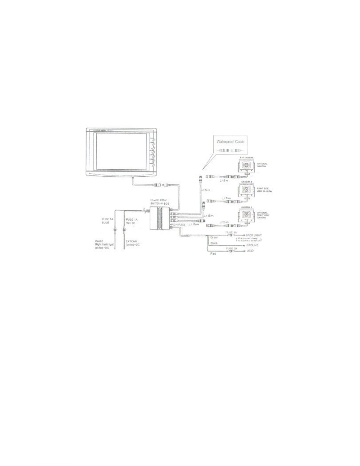
Connections
System uses a maximum of 3 cameras
OPTIONAL
Connect the RED wire to the (10V–32V DC) power terminal, which is
energized with the ignition key.
Connect the BLACK wire to the metal portion of the vehicle or the negative
battery post.
Connect the GREEN wire to the switched power output terminal of the “R”
(reverse) gear.
-10-

When you turn the ignition key to the Accessory or ON position, power is
supplied to the monitor.
To power the monitor push the ON/OFF power button. The monitor is
turned off when the ignition key is in the off position
When you set the gear lever in the reverse position, the monitor is turned
on and the picture from the Camera 1 appears.
Operating Instructions
Care & Maintenance
•If your vehicle has been parked in direct sunlight resulting in a
considerable rise in temperature inside the vehicle, allow the unit to
cool before operating
•Clean the unit with a slightly damp soft cloth.Use a mild household
detergent. Never use strong solvents such as a thinner or benzine as
they might damage the finish of the unit.
-11-

Monitor
TV System EIA
Picture: 5.6”TFT LCD Color monitor with
OSD (On-Screen Display) function
Power Source 12V DC ±10%
Power Requirements 10V ~ 32V
Operating Temp. -10°C ~ +60°C
Dimensions 174 (W) x 129 (H) x 36 (D) mm
Weight 540 g
Specifications
Camera
Image Device 1/4”Interline transfer type Color CCD
Effective pixels 270, 000 (EIA) pixels
Scanning System Internal SYNC
Horizontal Res. 330 TV lines
Min. Illumination 1.5 Lux, F=2.0
Field of view 140°diagonal
Power Input 12V DC ±10 %
Power Consumption 120 mA (Max)
Operating Temp. -30°C ~ +60°C
Weight 330 g
As our products are subject to continuous improvement, SVII and its subsidiaries reserve the right to modify
product design, specifications and prices, without notice and without incurring any obligation. E&OE -12-
Table of contents
Other Sentinel CCTV Automobile Accessories manuals


Popular Automobile Accessories manuals by other brands


Kingbird
Kingbird RV A Series user manual

Dometic
Dometic Catalina 2500 Installation & operating instructions

Roadmaster
Roadmaster Invisibrake 8700 installation instructions

Kargo Master
Kargo Master 40933 Instruction guide

JMS
JMS DAYTONA SENSORS Super Speedway CD-1 installation guide

ConWys
ConWys 21500610C Fitting instructions