STEPS 4, 5, 6, 7 & 8
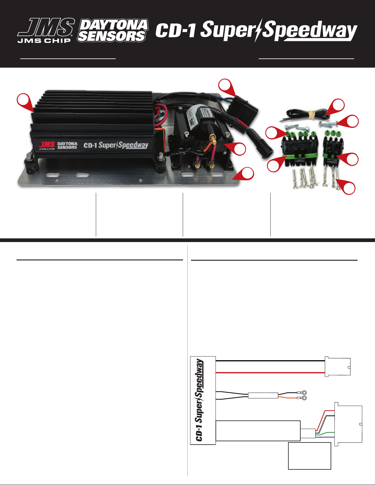
4. Plug the large weatherpack connector into the existing
vehicle connector.
5. Turn on the battery disconnect switch, start the engine, and
verify the correct operation of the ignition. Tach output is
compatible with all aftermarket tachometers that utilize the
industry standard 0-12v square wave signal. If your timing
has changed signicantly after the installation, verify that the
MAG +/MAG - wires are not reversed.
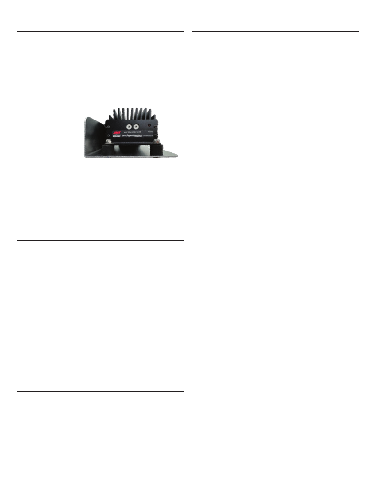
6. Two Rotary Dials
on the front of the
Super Speedway
Ignition control the
maximum RPM (real
time adjustment –
RPM can be adjusted when the engine is running between
60–99 [60=6000 RPM, 99=9900 RPM].
7. Ignition timing curve is determined by the distributor
(locked = xed ignition timing or the ignition curve will match
your distributor’s spring/weights/rpm). While cranking -
Ignition timing is automatically retarded (10 degrees).
8. Reconnect the battery. Start engine & verify ignition timing.
SWITCH SETTINGS & STATUS LED
The front panel of the Super Speedway CD-1 has two rotary
switches and a status LED.
- The status LED will illuminate when the ignition switch is turned
on. If an ignition fault condition occurs when powering on the
igntion, the status LED will BLINK.
- The most common fault is a loss of ignition trigger signal from
the magnetic pickup. If the engine turns off (without turning off
the ignition) the LED will blink, this is NORMAL due to signal loss.
Maximum RPM Limit Switch Settings
The maximum RPM limit switches are on the end plate. The RPM
limit switches can be adjusted when the engine is running, and
they can be set to a value between 6,000 RPM and 9,900 RPM.
00-99 Maximum RPM limit setting X100 (i.e. switch setting
63 = 6,300 RPM, 83 = 8,300RPM and 99 = 9,900 RPM)
SPARK PLUGS & WIRES
TROUBLESHOOTING
- Did the engine run properly before installation of the CD-1?
If not, remove the CD-1, reinstall the original ignition system and then
nd and correct the original problem.
- Did the CD-1 function correctly before the problem occurred?
If the answer is yes, did you change anything that may have affected it?
To isolate the problem, go back to the last setup that was OK. If the
engine will not start, runs intermittently, or misres, try these steps:
• Status LED Doesn’t Illuminate
If the status LED doesn’t illuminate after the ignition switch is turned on,
check power and ground connections. Use a voltmeter to verify +12V is
available at BOTH the heavy gauge battery + red wire and the thin red
ignition switch wire with the ignition switch in BOTH the RUN and START
switch positions.
The CD-1 requires a minimum of +9V when the ignition switch is rst
turned on. During cranking, the unit will continue to operate down to
+4.5V and under high rpm operation a min of +10v is required.
• Engine Will Not Start
If the status LED illuminates when the ignition switch is turned on, but the
engine will not start, verify that the status LED blinks while the engine is
cranking.
If the status LED doesn’t blink during cranking, the unit is not getting
a trigger signal. Verify that trigger module is not bad, verify that the
distributor is turning and that the signal wiring is not shorted together or to
ground.
If the status LED blinks, but engine will not start, verify your base ignition
timing and recheck coil primary connections or replace coil.
Intermittent Operation or Misre at High RPM
1. Misre at high RPM is usually not an electrical problem with the CD-1.
Common causes include: bad spark plug, wire, cap, rotor, coil failure or
arcing at spark plug boots or within the distributor.
2. For vehicles without an alternator, low battery voltage may cause misre
at high RPM. Verify that the battery is fully charged or try replacing the
battery.
3. To avoid electrical noise problems, route magnetic trigger wiring away
from any coil or spark plug wires. Use only spiral core spark plug wires.
Do not use solid copper core or carbon core resistance wires.
4. Check for broken, loose, or corroded connections. Verify correct air gap
for magnetic pickup. Check distributor for loose, missing, or jammed
parts in advance mechanism.
5. Verify that spark plugs are proper type, gap size, and heat range.
6. Replace spark plugs, spark plug wires, and distributor rotor and cap.
7. Ignition run-on. If the engine continues to run after the ignition switch
is turned off, current is leaking back into the CD-1 through the charging
system indicator lamp. GM or Ford models with an external voltage
regulator will require installation of a diode.
To avoid electrical noise that may interfere with the CD-1 or other
on board computer and radio equipment, resistor spark plugs are
recommended, and spiral core RFI/EMI suppression type spark
plug wires are required. Optimum spark plug gap for a normally
aspirated racing engine is typically between 0.030” and 0.045”.
Do not use solid copper or high resistance carbon core spark plug
wires. Optimum spark plug wire resistance is 50-500 ohms per
foot. Most high-quality spiral core silicone racing plug wires are
compatible with this ignition system.
Left= 1000's | Right= 100's