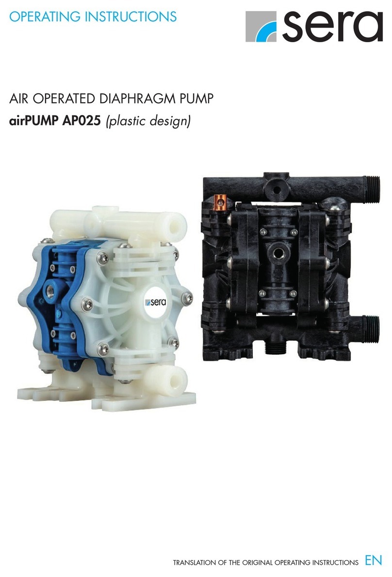
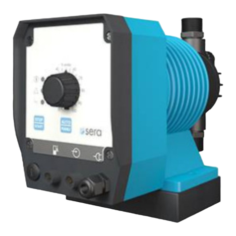
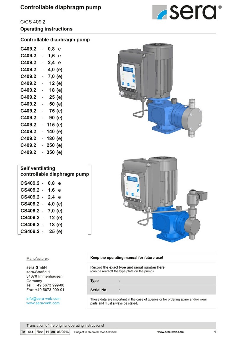
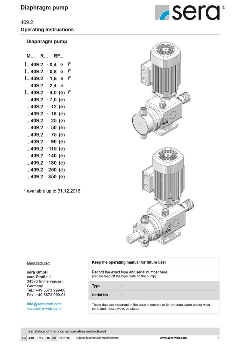
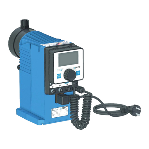
Sera 409.2 ML Series User manual

( ) *
( ) *
( ) *
* available until 31.12.2016

Multi-layer diaphragm pump
Serie 409.2 ML
Operating instruction
2 www.sera-web.com Technical modifications reserved! TA
431 Rev. 8 en 06/2015
Content:
1General...................................................................4
2Types......................................................................4
2.1 Model key...............................................................4
2.2 Type plate...............................................................4
2.3 Materials.................................................................5
2.4 Viscosity, dosing medium........................................5
2.5 Dosing range ..........................................................5
2.6 Noise test................................................................5
3Safety instructions ..................................................5
3.1 Quality instructions..................................................5
3.2 Marking of instructions............................................5
3.2.1 Marking of instructions (operating manual)....................5
3.2.2 Marking of instructions (Product)....................................5
3.3 Qualification and training of personnel ....................5
3.4 Dangers in case of inobservance of the safety
instructions .............................................................6
3.5 Safety-conscious working .......................................6
3.6 Safety instructions for the operator..........................6
3.7 Safety instructions for maintenance, inspection and
installation...............................................................6
3.8 Arbitrary modification and spare parts production ...6
3.9 Improper use ..........................................................6
3.10 Proper use..............................................................6
3.11 Personal protection for service and maintenance....6
3.12 Utilities....................................................................7
4Transportation and intermediate storage.................7
4.1 General...................................................................7
4.2 Transport................................................................7
4.3 Storage...................................................................7
5Assembly groups of multi-layer diaphragm pump....8
6Technical data ........................................................9
6.1 Dimensions.............................................................9
6.2 Technical data......................................................11
6.2.1 Output data...................................................................11
6.2.2 Motor data BG71 ..........................................................11
7Functional discription.............................................12
7.1 General .................................................................12
7.2 Assembly groups of the multi-layer diaphragm
pumps 409.2 ........................................................12
7.2.1 Stroke mechanism........................................................12
7.2.2 Stroke length adjustment..............................................12
7.2.3 Assembly pump ............................................................14
7.2.4 Pump body....................................................................15
7.2.5 Suction-/Pressure valve................................................15
7.2.6 Stroke frequency transmitter (optional) ........................15
7.2.7 Diaphragm rupture monitoring......................................16
7.3 Driving motor.........................................................17
7.3.1 Motor connection (standard).........................................17
7.3.2 Direction of rotation.......................................................17
7.3.3 Terminal box .................................................................17
7.3.4 Start-up.........................................................................17
7.3.5 Motor protection............................................................17
7.3.6 Maintenance of the drive motor....................................18
7.3.7 Restart...........................................................................18
8Installation.............................................................18
8.1 Installation instructions..........................................18
8.1.1 Provide for an overpressure protection ........................19
8.1.2 How to prevent a backflow of the dosing medium........20
8.1.3 How to eliminate undesired siphoning..........................20
8.1.4 How to ensure an airless suction..................................21
8.1.5 Installing the empty-tank alarm.....................................21
8.1.6 How to avoid an emptying of the suction line...............22
8.1.7 Line strainer ..................................................................22
8.1.8 Suction via a siphon pipe..............................................23
8.1.9 In case of slightly degassing dosing media..................23
8.1.10 Damping of the pulsation..............................................23
9Operation in explosion-hazardous areas ...............25
9.1 General .................................................................25
9.2 Identification..........................................................25
9.3 Installation.............................................................25
9.3.1 General .........................................................................25
9.3.2 Working in explosion-hazardous areas ........................25
9.4 Potential equalisation ............................................25
9.5Start-up.................................................................25
9.6 Operation ..............................................................25
9.6.1 General .........................................................................25
9.6.2 Degassing of the dosing medium.................................25
9.6.3 Temperature indications...............................................25
9.7 Maintenance..........................................................25
10 Maintenance..........................................................26
10.1 Wearing parts........................................................26
10.2 Spare parts............................................................26
10.3 Spare- and wearing parts ......................................27
10.4 Replacing the diaphragm.......................................29
10.4.1 General .........................................................................29
10.4.2 Diaphragm change .......................................................29
10.5 Oil change.............................................................32
11 Lubricant ...............................................................32
11.1 Lubricant in stroke mechanism..............................32
12 Fault analysis and corrective action.......................32

Multi-layer diaphragm pump
Serie 409.2 ML
Operating instruction
TA
431 Rev. 8 en 06/2015 Technical modifications reserved! www.sera-web.com 3
13 Foreseeable misuse..............................................34
13.1 Transport..............................................................34
13.2 Assembly and installation......................................34
13.3 Start-up:................................................................34
13.4 Operation..............................................................34
13.5 Maintenance/Repair..............................................34
13.6 Cleaning ...............................................................35
13.7 Shut-down ............................................................35
13.8 Disassembly.........................................................35
13.9 Disposal................................................................35
14 Decommissioning .................................................35
15 Disposal................................................................35
15.1 Dismounting and transport....................................35
15.2 Complete disposal ................................................35

Multi-layer diaphragm pump
Serie 409.2 ML
Operating instruction
4 www.sera-web.com Technical modifications reserved! TA
431 Rev. 8 en 06/2015
1 General
Before commissioning and during operation of the sera multi-
layer diaphragm pump it is necessary to follow the relevant
local instructions.
The sera multi-layer diaphragm pump is delivered ready for
connection. Carefully read these instructions and especially
the safety instructions herein contained before putting the
diaphragm pump into service.
2 Types
2.1 Model key
Example:
Multi-layer diaphragm pump Type R 409.2-17 ML
R
409.2 17 ML
Information for adjustment
Mnot adjustable
Rmanual adjustable
(stroke length adjustment)
Fwith three phase motor, suitable for
operation with frequency converter
(Combination ‚RF’ is possible!)
R
409.2
17
ML
Indication of type series/stroke drive
R 409.2
17
ML
Indication of nominal delivery rate
This number states the nominal delivery rate in
litres/hour.
(standard version referring to water)
R
409.2
17
ML
Indication of the execution of the plug-in pump
ML Execution Multi-layer diaphragm
2.2 Type plate
Each sera multi-layer diaphragm pump is factory provided with
a type plate. The following information can be found on this
type plate.
1 2 3 4 5 6 7
Fig. 01 Type plate
Explanation of the indications
on the type plate
1
Typ
Pump type
2
Nr.
Serial-No. (Pump)
3 P1min/max [bar]
Minimum/maximum permissible
pressure in the pump inlet
Minimum/maximum permissible pres-
sure in the inlet cross section which the
pump is applicable for. Please consider
that the pressure depends on rotation
speed, delivery rate, t
emperature and
static pressure at inlet.
4 P2max [bar]
Maximum permissible pressure in
the pump outlet
Maximum permissible pressure in the
outlet cross section which the pump is
applicable for. Please consider that the
pressure depends on rotation speed,
delivery rate, temperature and static
pressure at outlet.
5 QNl/h
Nominal delivery rate
Delivery rate which the pump was or-
dered for, based on the nominal rotation
speed nN
, the nominal delivery height
p2
max. and the dosing medium stated
in the supply contract.
6
nN1/min
Nominal stroke frequency for
7 Hydrfl. [cm3]
Buffer fluid
Quantity of buffer fluid in the diaphragm
ring (in the case of double diaphragm
pumps)
Tab. 01 Designation type plate

Multi-layer diaphragm pump
Serie 409.2 ML
Operating instruction
TA
431 Rev. 8 en 06/2015 Technical modifications reserved! www.sera-web.com 5
2.3 Materials
The materials used are indicated in the order confirmation.
2.4 Viscosity, dosing medium
The multi-layer diaphragm pump is suitable for fluids with vis-
cosities < 100 mPas.
2.5 Dosing range
The flow capacity of the multi-layer diaphragm pump can be
controlled manually via the stroke length adjustment (0...100%)
The linear dosing range is between 20…100%
2.6 Noise test
The measured sound pressure level acc. to DIN 45635 for the
diaphragms pumps is between 50 and 60 dB (A).
3 Safety instructions
CAUTION !
If the pump should be operated in explosion-hazardous
areas, please also note the instructions in Chapter 9!
3.1 Quality instructions
Observance of these operating instructions and, in particular,
safety instructions, helps to
•Avoid danger to staff, machines, and environment.
•Increase the reliability and service life of the equipment
and the entire installation.
•Reduce expenses for repairs and downtimes.
The sera quality management and quality assurance system
for pumps, installations, fittings and compressors is certified
according to ISO 9001:2008.
The sera multi-layer diaphragm pump is compliant with the
valid safety requirements and accident prevention regulations
CAUTION !
Always keep these operating instructions within reach at
the workplace!
CAUTION!
Pay attention to the safety data sheet of the medium
conveyed! Take appropriate accident prevention
measures to avoid that operators are endangered by the
used conveying media!
3.2 Marking of instructions
3.2.1 Marking of instructions
(operating manual)
Special notes in these operating instructions are marked with
the general danger symbol
(safety symbol according to DIN 4844 – W9)
The safety sign appears in the following cases:
•If improper observance or non-observance of the operat-
ing manual, work instructions, specified operating proce-
dures and similar can lead to personal injury or accidents.
•If improper observance or non-observance of the operat-
ing manual, work instructions, specified operating proce-
dures and similar can lead to damage to property.
•Due to danger of causticization personnel must wear pro-
tective clothing (safety goggles, safety gloves and safety
apron) for maintenance and repair work on parts which
come into contact with hazardous products or for chang-
ing the containers.
3.2.2 Marking of instructions
(Product)
Information signs which are directly attached to the pump,
such as arrows indicating the direction of rotation or signs for
fluid connections must be adhered to and kept in a legible
condition.
This especially applies to the type plate of the pump.
3.3 Qualification and training of personnel
The personnel who operate, maintain, carry out inspections or
install the machine must be suitably qualified for their tasks.
The operator has to define clearly the responsibility, and the
supervision of the personnel. If the personnel do not have the
knowledge required, then the operator has to carry out
corresponding training and instructions. Such a training can be
realized - if required - upon order of the operator of the
machine by the manufacturer / supplier. The operator has to
ensure furthermore that the personnel have understood the
contents of the operating instructions completely.

Multi-layer diaphragm pump
Serie 409.2 ML
Operating instruction
6 www.sera-web.com Technical modifications reserved! TA
431 Rev. 8 en 06/2015
3.4 Dangers in case of inobservance of the
safety instructions
The inobservance of the safety instructions may result in
personal injuries, hazards to the environment and damages to
the pump.
The inobservance of the safety instructions may have the
following consequences:
•Failure of important functions of the pump
•Failure of prescribed methods for maintenance and
upkeep
•Danger to persons by electrical, mechanical and chemical
influences
•Danger to the environment due to leakage of hazardous
media
3.5 Safety-conscious working
The safety instructions specified in this operating manual, the
national regulations for accident prevention, the safety regula-
tions for the pumped medium valid at the place of installation
as well as internal working-, operating-, and safety instructions
of the owner are to be observed.
3.6 Safety instructions for the operator
Leakage of dangerous conveying media and materials must be
drained off so that a risk to persons and the environment can
be excluded. The legal regulations are to be adhered to.
Dangers caused by electrical energy are to be prevented.
3.7 Safety instructions for maintenance,
inspection and installation
The operator has to ensure that all maintenance, inspection
and installation tasks are carried out by authorized and
sufficiently qualified personnel, who have carefully read and
understood the operating instructions.
Only those spare parts and materials are to be used that
satisfy the requirements of the relevant operating conditions.
Loosen screws and connections only when the system is not
under pressure.
3.8 Arbitrary modification and spare parts
production
Modifications of or changements to the machine are only
allowed after previous agreement of the manufacturer. Original
spare parts and accessories that are authorized by the
manufacturer are essential for safety reasons.
CAUTION!
Use of other parts may result in loss of guarantee for
damages arising as a consequence thereof.
3.9 Improper use
The operating safety of the supplied multi-layer diaphgram
pump is only guaranteed if the product is used as intended,
according to the descriptions in Chapter 3.10 of these operat-
ing instructions.
3.10 Proper use
The sera diaphragm pump is only to be deployed according to
the intended purpose stated in the product description and the
acceptance test certificate.
If the pump is to be used for other purposes, it is required to
consult sera beforehand to settle whether the multi-layer
diaphragm pump is suitable for the new usage!
The criteria for determining whether the multi-layer -diaphragm
pump is appropriately used are:
•Characteristics of the medium conveyed (refer to the
safety and product data sheet of the used medium – the
safety data sheet is to be provided by the supplier /
operator of the conveying medium).
•Stability of the materials which have contact with the
medium conveyed
•Operating conditions at the place of installation
•Pressure and temperature of the conveying and cooling
medium
•Voltage supply
3.11 Personal protection for service and
maintenance
In order to avoid risks to health, the provisions of the German
Ordinance on Hazardous Substances (GefStoffV) (§14 Safety
Data Sheet) and relevant national safety regulations for the
dosing medium must strictly be adhered to.
In case of accidents check whether the following substances
are emitted:
•Leakage of fluids
•Leakage of fumes
•Noise emissions (sound level)
Emissions must be monitored by monitoring systems of the
total installation.
CAUTION!
Use protective clothing, gloves, breathing mask and
suitable goggles for face protection!
CAUTION!
Personal protective equipment must be provided by the
equipment operator at all times!

Multi-layer diaphragm pump
Serie 409.2 ML
Operating instruction
TA
431 Rev. 8 en 06/2015 Technical modifications reserved! www.sera-web.com 7
3.12 Utilities
If not agreed otherwise in the contract conditions, the sera
multi-layer diaphragm pump will always be supplied with the
necessary utilities.
(For type and quantitiy of utilities/lubricants, see Chapter 11)
4 Transportation and intermediate storage
4.1 General
Before shipment sera products are tested for proper
functioning and quality.
An undamaged packaging protects the device during subse-
quent storage and should only be opened when the multi-layer
diaphragm pump will be installed.
CAUTION !
The packaging material must be disposed of
appropriately!
4.2 Transport
Select a hoist which is adapted to the weight of the pump and
attach it to the motor flange of the pump (see Fig. 02).
Fig. 02 Transport/Handling
4.3 Storage
An undamaged packaging protects the device during
subsequent storage and should only be opened when the
multi-layer diaphragm pump will be installed.
A proper storage will increase the service life of the pump.
Proper storage means avoidance of negative influences, such
as heat, humidity, dust, chemicals etc.
The following storage conditions must be observed:
•Storage place: cool, dry, dust-free and slightly ventilated.
•Storage temperature between +2°C and + 40°C.
•Humidity not more than 50%.
•The maximum storage time for the standard system is 12
months.
If this value is exceeded, products made from metal should be
sealed in foil and protected against condensation water using
suitable desiccants.
Do not store solvents, fuels, lubricants, chemicals, acids,
disinfectants and similar together with the product in the
storage room.

Multi-layer diaphragm pump
Serie 409.2 ML
Operating instruction
8 www.sera-web.com Technical modifications reserved! TA
431 Rev. 8 en 06/2015
5 Assembly groups of multi-layer diaphragm pump
The multi-layer diaphragm pump may be assembled of the
following (main) components:
•Stroke mechanism with drive
•Stroke length adjustment
•Assembly pump
•Pump body
•Valves
Options:
•Stroke frequency transmitter
•Actuator
•Frequency converter
Not illustrated:
•Actuator for Ex-area
•pneumatical actuator
•EExeIIT4 – Driving motor
Blind plug
Driving motor for operation Driving motor (M-Execution)
with frequency converter mounted
frequency converter
manual stroke
length adjustment
manual stroke length
adjustment with
position indicator
Pressure valve
Pump body,
diaphragm rupture signal
by pressure switch
Ex-Execution
Stroke length adjustment
by actuator
Stroke frequency transmitter
(with Inductive-contact)
Assembly pump Suction valve
Pump body,
diaphragm rupture signal
by pressure switch
Pump body,
optical, local indication of
diaphragm rupture by Manometer
Fig. 03 Assembly - overview

Multi-layer diaphragm pump
Serie 409.2 ML
Operating instruction
TA
431 Rev. 8 en 06/2015 Technical modifications reserved! www.sera-web.com 9
(zumAbnehmender
Stellmotorhaube)
min. 200
H2
H3
B A
C
E
FD148
K1
K2
K3
K4 ... 6
H1
DN
10
75
154M1... 4
21
N1... 4
7
80
98
98
80
30
39
M8, d=6,5
Befestigungsbohrungen
T
6 Technical data
6.1 Dimensions
Fig. 04 Dimensions
(for removing
the actuator cover)
M 8 / Ø 6,5
mounting
holes

Multi-layer diaphragm pump
Serie 409.2 ML
Operating instruction
10 www.sera-web.com Technical modifications reserved! TA
431 Rev. 8 en 06/2015
Tab. 02
Dimensions
All dimensions in mm !
Pump type
R409.2-
11 ML
R409.2-
17 ML
R409.2-
30 ML
R409.2-
45 ML
R409.2-
72 ML
R409.2-
110 ML
R409.2-
150 ML
R409.2-
220 ML
Valves
A
Single valves PVC --- --- 93 93 97 97 --- 124 --- 124
Single valves
1.4571/1.4581 --- --- --- --- --- --- 127 --- 127 ---
Single valves
PP-FRP, PVDF-FRP
--- --- --- --- 94 94 127 --- 127 ---
Double valves
PP-FRP, PVDF-FRP
83 83 90 90 --- --- --- --- --- ---
Double valves
1.4571/1.4581
83 83 91 91 95 95 --- --- --- ---
Chamber valves PVC, 1.4571 88 88 --- --- --- --- --- --- --- ---
B
Single valves PVC --- --- 100 100 104 104 --- 143 --- 143
Single valves
1.4571/1.4581
--- --- --- --- --- --- 127 --- 127 ---
Single valves
PP-FRP, PVDF-FRP
--- --- --- --- 94 94 127 --- 127 ---
Double valves
PP-FRP, PVDF-FRP 83 83 90 90 --- --- --- --- --- ---
Double valves
1.4571/1.4581
--- --- 91 91 95 95 --- --- --- ---
Chamber valves PVC, 1.4571 88 88 --- --- --- --- --- --- --- ---
C Connection thread
suction-/pressure valve
G ¾ G ¾ G ¾ G ¾ G ¾ G ¾
G1¼
G1
G1¼
G1
DN Nominal diameter 5 5 8 8 8 8 20 15 20 15
D Assembly pump 43 43 40 40 44 44 43 43
Pump body (PD)
E Centre – screw-in thread for valves (1.4571) 16 16 18 18 21 21 33 33
Centre – screw-in thread for valves
(PP, PVC, PVDF)
24 24 24 24 27 27 33 33
F Pump body, 1.4571 (without front plate) 49 49 51 51 54 54 80 80
Pump Body, PP, PVC, PVDF (with front plate) 62 62 65 65 65 65 83 83
H1Pumpbody with Manometer (1.4571) 134 134 138 138 141 141 155 155
Pump body with Manometer (PVC, PP, PVDF) 134 134 138 138 141 141 155 155
H2Pump body with pressure switch (1.4571) 139 139 144 144 146 146 161 161
Pump body with pressure switch
(PVC, PP, PVDF)
139 139 144 144 146 146 161 161
H3
PB with pressure switch EX-execution
(1.4571)
211 211 216 216 221 221 234 234
PB with pressure switch EX-execution
(PVC, PP, PVDF) 222 222 226 226 230 230 245 245
Stroke length
adjustment (SLA)
K1
Blind flange for execution without
stroke length adjustment
8 8 8 8 8 8 8 8
K2Manual stroke length adjustment (max.) 70 70 70 70 70 70 70 70
K3Manual stroke length adjustment
with position indicator
110 110 110 110 110 110 110 110
K4Electrical actuator 240 240 240 240 240 240 240 240
K5Electrical actuator with PMR2 320 320 320 320 320 320 320 320
K6Electrical actuator Ex-execution 470 470 470 470 470 470 470 470
Driving motor (BC 71)
M1Driving motor (Standard) 225 225 225 225 225 225 225 225
N1120 120 120 120 120 120 120 120
M2Driving motor for operation with
Frequency converter (FU) 225 225 225 225 225 225 225 225
N2120 120 120 120 120 120 120 120
M3AC - Motor 175 175 175 175 175 175 175 175
N3100 100 100 100 100 100 100 100
M4EExeIIT4 - motor 200 200 200 200 200 200 200 200
N4100 100 100 100 100 100 100 100
Option T Stroke frequency transmitter 110 110 110 110 110 110 110 110
Stroke
mechanism
Amongst others
, dimensions for fastening the
pump
See Fig. 04

Multi-layer diaphragm pump
Serie 409.2 ML
Operating instruction
TA
431 Rev. 8 en 06/2015 Technical modifications reserved! www.sera-web.com 11
6.2 Technical data
6.2.1 Output data
Type
Pump data
Nominal capacity (2)
adjustable by changing
lift of strokes
Maximum permissible
pressure at outlet of
pump
Minimum- / maximum
permissible pressure at
inlet of pump
max. suction height (1)
Recommended
nominal diameter of the
connecting pipes
Nominal stroke
frequency
max. stroke length
Motor size
(standard execution)
Q
N
l/h
p
2
max.
p
1
min. / max
.
WC DN min -1 h100 BG
50 Hz 60 Hz bar bar m mm 50 Hz 60 Hz mm
..409.2 – 11 ML 0-11 0-13,2
10 (3)
-0,3/0 3 10 100 120 4 71
20
..409.2 – 17 ML 0-17 0-20
10 (3)
-0,3/0 3 10 150 180 4 71
20
..409.2 – 30 ML 0-30 0-36
10 (3)
-0,3/0 3 10 100 120 6 71
16
..409.2 – 45 ML 0-45 0-54
10 (3)
-0,3/0 3 10 150 180 6 71
16
..409.2 – 72 ML 0-72 0-86 10 -0,3/0 3 15 100 120 8 71
..409.2 – 110 ML 0-110 0-132 10 -0,3/0 3 15 150 180 8 71
..409.2 – 150 ML 0-150 0-180 4 -0,3/0 3 15 100 120 10 71
..409.2 – 220 ML 0-220 0-264 4 -0,3/0 3 15 150 180 10 71
Tab. 03 Output data
(1) Achievable suction height with media similar to water and filled suction line
(2) Linear dosing range between 20 and 100% stroke length
(3) Maximum pressure for pump bodies made of plastics
6.2.2 Motor data BG71
Motor type Motor data
Power
Motor
rotation
speed
Mains
frequency
Voltage
range
Nominal
current
Protection
category
Heat class
ATEX
version
[kW] [min–1] [Hz] [Volt] [A] [IP]
50 Hz 60 Hz 50 Hz / 60 Hz 50 Hz / 60 Hz
Standard-Motor 0,37 ~1500 ~1800 50/60
PAY ATTENTION TO TYPE PLATE !
The data can be read off the
type plate on the drive motor of
the respective diaphragm pump!
55 F ---
Motor for operation
with frequency
converter 0,37 ~1500 ~1800 50/60 55 F ---
AC - Motor 0,37 ~1500 --- 50 55 F ---
EExeIIT4- Motor 0,25 ~1500 --- 50 55 F II2G EExe IIT4
EExdeIIT4-Motor
(pressure-proof)
0,25 ~1500 --- 50 55 F II2G EExde IIT4
Tab. 04 Motordaten

Multi-layer diaphragm pump
Serie 409.2 ML
Operating instruction
12 www.sera-web.com Technical modifications reserved! TA
431 Rev. 8 en 06/2015
6
4 5
%0
20
40
60
80
70
50
10
30
7 Functional discription
7.1 General
sera multi-layer diaphragm pumps are run-dry safe oscillating
displacement pumps that are characterised by high tightness
of the dosing head. The liquid is conveyed by a deformable
multi-layer diaphragm.
Multi-layer diaphragm pumps consist of the following (main)
components:
•Driving motor
•Stroke mechanism
•Stroke length adjustment
•Assembly pump
•Pump body
•Suction- and pressure valve
Driving motor
Vent screw
Pressure
valve
Stroke length
adjustment
Stroke
Suction mechanism
valve Assembly pump
Pump body
Fig. 05 Assembly groups
7.2 Assembly groups of the multi-layer
diaphragm pumps 409.2
7.2.1 Stroke mechanism
Function:
Multi-layer diaphragm pumps of this type series use a rotary
cam drive to transmit the rotation of the drive motor to the dis-
placement body.
In case of the rotary cam drive, the eccentric provides the
pressure stroke while the suction stroke is performed by a
pressure spring (return spring).
The effective stroke length can be changed by means of an
adjustable scale knob which prevents the connecting rod from
following the rotary cam up to the rear dead centre during suc-
tion stroke (see stroke length adjustment).
Scale knob
(stroke length adjustment)
Stroke mechanism
Return spring Eccentric
Adjusting spindle
Fig. 06 Stroke mechanism
7.2.2 Stroke length adjustment
General
The delivery rate of the pump is regulated by changing the
stroke length. The stroke length is infinitely variable between
0% and 100%.
A linear dosing behaviour is achieved with stroke length ad-
justments between 20% and 100%.
7.2.2.1 Manual stroke length adjustment
(Standard)
The effective stroke length of the connecting rod is changed by
turning the scale knob.
The stroke length can be adjusted both during operation and
standstill (in unpressurized condition) of the pump.
The set stroke length can be read off a scale, e.g. 75% (see
Fig. 07).
With the 20-steps adjustment on the scale knob, the stroke
length can be set individually with a tolerance of 0.5%.
Turning counter-clockwise the effective stroke length
(see Fig. 07) increases, the delivery
rate increases.
Turning clockwise the effective stroke length
decreases, the
delivery rate decreases.
Scale knob
Fig. 07 Stroke length adjustment/Scale knob

Multi-layer diaphragm pump
Serie 409.2 ML
Operating instruction
TA
431 Rev. 8 en 06/2015 Technical modifications reserved! www.sera-web.com 13
0
10
20
3040 50 6070
80
90
100
%
7.2.2.2 Manual stroke length adjustment by
a dial scale with indication of percent
(option)
The stroke length is adjusted by turning the hand wheel. The
stroke length can be adjusted both during operation and
standstill (in unpressurized condition) of the pump.
Turning counter-clockwise the effective stroke length
(see Fig. 08) increases, the
delivery rate increases.
Turning clockwise the effective stroke length
decreases, the
delivery rate decreases.
The adjusted stroke length
can be read off the percent
scale (the example shows a
set stroke length of 65%).
Fig. 08 Stroke length adjustment with position indicator
In delivery state, the stroke length adjustment is factory set to
50%.
CAUTION!
The dial scale with indication of percent may become
misadjusted during transport.
If the indicator does not match the 50% setting, then the
percent scale must be re-adjusted during operation(!) of
the pump!
Set screw
Hand wheel
(Adj. spindle)
Dial scale with indication of percent
Fig. 09 Stroke length adjustment with position indicator
Adjusting the percent scale:
•switch the multi-layer diaphragm pump on
•loosen the set screw
•remove the percent scale from the hand wheel
•manually turn the percent scale to 0% setting
•use the hand wheel to set the stroke length to 0%. Turn
hand wheel clockwise until there is no further stroke
movement (push rod does no longer hit the adjusting
spindle)
•insert percent scale again
•use the set screw to secure the percent scale to the hand
wheel
•adjust desired stroke length
7.2.2.3 Automatic stroke length adjustment
by an electrical actuator
The electrical actuator is directly mounted to the stroke mech-
anism of the dosing pump. A clutch transmits the rotary motion
of the actuator driveshaft to the adjusting spindle. The axial
displacement is compensated in the clutch.
Dosing pump
Actuator
Stroke Clutch
mechanism
Abb. 10 Stroke length adjustment by actuator
In case of dosing pumps with electrical actuator, a manual ad-
justment of the stroke length on the pump is no longer possi-
ble.
(Exception: actuator with hand wheel)
The actuator is standardly equipped with two integrated limit
switches and a position potentiometer for position feedback.
Both limit switches are factory set so that the drive will switch
off at a stroke length of 0% and 100%, even if a control voltage
is applied.
This guarantees that adjustments can only be made within the
permissible range. The position potentiometer is driven by a
safety clutch which prevents damage caused by incorrectly
adjusted limit switches.
Activation is performed by appropriate control units (see sera -
accessories)

Multi-layer diaphragm pump
Serie 409.2 ML
Operating instruction
14 www.sera-web.com Technical modifications reserved! TA
431 Rev. 8 en 06/2015
The set stroke length can be read off on the pump (percent
scale).
Information about the electrical connection is given inside the
cover of the actuator.
CAUTION !
The adjustment is only possible when the pump is run-
ning.
7.2.2.4 Automatic stroke length adjustment
by an electrical actuator with inte-
grated positioner (PMR2)
same as Chapter 7.2.2.3, additionally:
•PMR2 positioner
This PMR2 positioner integrated in the actuator enables an
actuator setting from 0…100% that is proportional to the con-
nected input signal.
As an option, the actuator can also be provided with a collec-
tive interference signal.
Information about the electrical connection is given inside the
cover of the actuator.
7.2.2.5 Automatic stroke length adjustment
by an electrical actuator (Ex-
execution)
Pay attention to the documents attached to the actuator.
7.2.2.6 Automatic stroke length adjustment
by a pneumatic actuator
Pay attention to the documents attached to the actuator.
7.2.3 Assembly pump
General
Function
The diaphragm consists of three layers and is linked with the
connecting rod. Only the front layer, the so-called working dia-
phragm, comes into direct contact with the dosing medium.
The middle layer functions as a signalling diaphragm. In case
of a rupture of the working diaphragm, the medium is fed to the
diaphragm rupture signalling in a controlled manner. The dia-
phragm rupture can be analysed either electrically or visually
(local). The third membrane functions as protection diaphragm
and ensures that no dosing medium will leak out, even not if
the working diaphragm has ruptured.
A diaphragm rupture is indicated either by a manometer (visu-
al) or, optionally, by a pressure switch (electrical).
Protection diaphragm
Signal diaphragm
Working diaphragm
Connecting rod
Pressure valve
Pump body
Medium
Suction valve Mulit-layer diaphragm set
Abb. 11 Function principle of multi-layer diaphragm pump

Multi-layer diaphragm pump
Serie 409.2 ML
Operating instruction
TA
431 Rev. 8 en 06/2015 Technical modifications reserved! www.sera-web.com 15
7.2.4 Pump body
Depending on the applied backpressure, movements of the
plastic pump body in elastic materials are possible.
This does not affect the pumps’s durability or operating safety.
7.2.5 Suction-/Pressure valve
The pump valves are ball valves that only work properly in a
vertical position. The condition of the valves has a deciding
effect on the operating capability of the pump.
Valves must be exchanged as complete units.
When replacing the valves it is important to check the flow
direction (see Fig. 12).
CAUTION!
Pressure valve above; Suction valve below !
Flow direction
Fig. 12 Double valves, FRP-Execution
7.2.6 Stroke frequency transmitter (optional)
sera dosing pumps are oscillating displacement pumps with an
exactly defined stroke volume per each pump stroke.
If these dosing pumps should be used for automatic filling pro-
cesses or charge dosing, then the single pump strokes must
be determined and converted into electrical signals.
For this purpose, a stroke frequency transmitter (inductive con-
tactor) is added to the pump and reports each single pump
stroke to the evaluation unit (e.g. preselection counter, SPS-
control unit, etc.)
Stroke mechanism
of dosing pump
Cover
inductive
Contactor
Angle plug
with cable
Fig. 13 Stroke frequency transmitter
Technical data
Nominal voltage: 10 - 60 V DC
Constant current: < 200 mA
Current-limited
Connection design: Connector with 2m cable
LED (green): Indication for supply voltage
LED (yellow): Indication for switching status
Circuit diagram
CAUTION!
When switching inductive loads (protectors, relays, etc.),
surge protectors (varistors) must be fitted because of the
high self-induction voltage.
CAUTION!
In the case of use in explosion-hazardous areas, a NAMUR
design stroke frequency emitter is to be fitted (II2G EExia
IICT6, in compliance with ATEX95).
+
-
1 brown
4 black
3 blue
10-60 V
DC

Multi-layer diaphragm pump
Serie 409.2 ML
Operating instruction
16 www.sera-web.com Technical modifications reserved! TA
431 Rev. 8 en 06/2015
7.2.7 Diaphragm rupture monitoring
sera multi-layer diaphragm pumps are equipped with
a diaphragm rupture monitoring.
CAUTION!
For more detailed information about the indicators of the
diaphragm rupture monitoring, please see Chapter 17!
7.2.7.1 Visual diaphragm rupture monitoring
by manometer (only local signalling)
In case of a rupture of the working diaphragm, the medium
under pressure flows through a bore in the pump body to the
signalling manometer and causes a pointer deflection.
•Switch off the pump immediately
•Replace the diaphragm
Manometer
Working diaphragm
Pump body
Fig.14 Diaphragm rupture monitoring by manometer
CAUTION!
If the pump is operated with a backpressure that is only
slightly higher than the permissible minimum pressure of
p2=1bar, then the deflection of the pointer on the manome-
ter will also be slight.
During normal operation with intact membrane, the
manometer shows 0bar.
7.2.7.2 Diaphragm rupture monitoring
by Pressure switch
In case of a rupture of the working diaphragm, a pressure is
generated on the pressure switch. The present signal must be
evaluated and further processed in such a way that the pump
is switched off instantly.
Pressure switch
Working diaphragm
Pump body
Fig. 15 Diaphragm rupture monitoring by pressure switch
7.2.7.3 Diaphragm rupture monitoring
by Pressure switch (Ex-Area)
Pressure switch
(Ex-proof)
Working diaphragm
Pump body
Fig.16 Diaphragm rupture monitoring by
pressure switch (Ex)
CAUTION!
The pressure switch is factory set to a switching pressure
of ≤ 1bar. For this reason and in order to guarantee a cor-
rect dosing function, the pump should always be operated
with a pressure of ≥ 1bar!

Multi-layer diaphragm pump
Serie 409.2 ML
Operating instruction
TA
431 Rev. 8 en 06/2015 Technical modifications reserved! www.sera-web.com 17
W2 U2 V2
U1 V1 W1
L1 L2 L3
W2 U2 V2
U1 V1 W1
L1 L2 L3
W2 U2 V2
U1 V1 W1
L1 N
CB
7.3 Driving motor
sera multi-layer diaphragm pumps are driven either by a three-
phase motor or an AC motor.
7.3.1 Motor connection (standard)
In case of a three-phase motor
The motor connection depends on the voltage indication on
the type plate and the applied supply voltage.
Delta connection Y Star connection
Fig. 17 Circuit diagram(s) three-phase motor
Example:
Indication on the type plate: 230/400 V
Three-phase power system on site: 400 V
Correct motor connection: Y Star connection
In case of an AC motor
The AC motor has a main and an auxiliary winding. The run-
ning capacitor is switched in series to the auxiliary phase.
Fig. 18 Circuit diagram AC-motor
7.3.2 Direction of rotation
The direction of rotation of the drive motor is arbitrary.
7.3.3 Terminal box
Before closing the terminal box, please check that:
•all terminal connections are tightly fitted
•the interior is clean and free of foreign bodies
•unused cable entries are closed and screw plugs are
tightened
•the sealing is correctly inserted in the cover of the termi-
nal box; check proper condition of all sealing surfaces so
that the demands of the protection category are fulfilled.
7.3.4 Start-up
Preconditions:
Make sure that voltage and frequency correspond with the in-
dications on the type plate of the motor. Permissible voltage
tolerance (DIN VDE 0530)
for rated voltage + 10%
for rated voltage range +/- 5%
The connecting cable must be dimensioned according to the
motor characteristics.
Secure connecting cable with a strain relief.
The nominal motor power refers to an ambient temperature of
40°C and an installation site below 1000m above sea level.
Motor output will be reduced if these values are exceeded (see
VDE 0530).
Adapted for “moderate” groupe of climates according to IEC
721-2-1.
CAUTION !
The drive motor will heat by operation of the pump.
Do not touch the motor during operation!
7.3.5 Motor protection
Provide for adequate motor protective equipment in order to
protect the motor from overload (e.g. motor protection switch
with thermal overcurrent release).
Connect the ground wire to the marked earth screw in accord-
ance with VDE 0100.
CAUTION!
Fuses do not protect the motor.

Multi-layer diaphragm pump
Serie 409.2 ML
Operating instruction
18 www.sera-web.com Technical modifications reserved! TA
431 Rev. 8 en 06/2015
7.3.6 Maintenance of the drive motor
The electric motor should always be kept clean so that neither
dust, dirt, oil nor other contaminates may affect the correct op-
eration.
In addition, we recommend to ensure that:
•the motor does not produce strong vibrations
•suction and blowing openings for the supply of cooling air
are not closed or restricted (may lead to unnecessary
high temperatures in the windings).
The ball bearings inserted in the motor are lubricated for life.
7.3.7 Restart
Restart the system as described in Chapter 7.3.4 after mainte-
nance work of after longer periods of standstill.
8 Installation
CAUTION!
In case of operation in explosion-hazardous areas, the
instructions in Chapter 9 must also be followed!
8.1 Installation instructions
•The standard model of the pump is only approved for in-
stallation in dry rooms in a non-aggressive atmosphere,
at temperatures between +2°C and +40°C and at permit-
ted humidity until approx. 90%, altitude 1000 m above
sea level. (For operation in explosion-harzardous areas,
see Chapter 9).
•For dimensions of the pump connections and fixing holes,
see Fig. 04, Table 02.
•Install the pump in such a way that there is no vibration
and no tension and that it is aligned precisely.
•Install the pump at the optimum possible operating height.
Mount the pump in such a way that the valves are verti-
cal.
•Ensure that there is sufficient space around the pump
body and the suction and pressure valve so that these
parts may be easily dismantled, if required.
•The stroke length adjustment, indicator scale and visual
diaphragm rupture signalling must be easily accessible
and readable.
•Design the nominal diameters of the downstream pipes
and of the connections built into the system to be the
same size or larger than the inlet / outlet nominal widths
of the pump valves.
•To check the pressure ratios in the pipe system, we rec-
ommend to provide for connections for pressure gauges
(e.g. manometers) near the suction and pressure attach-
ments.
•Provide evacuation fittings
•Prior to connecting the pipes, remove the plastic caps on
the suction and pressure attachments of the pump.
•Check that the fixing screws for the pump body are tightly
fitted and, if necessary, retighten.
Torque for tightening the fixing screws
Pump body
without
mounting plate 15 NM
Pump body with mounting plate
15 NM
Plastic cap
Fixing screws
Plastic cap
Fig. 19 Multi-layer diaphragm pump with plastic caps
•For models with a built-on actuator, ensure sufficient
space for removal of the cover
(see Chapter 6.1 “Dimensions“)
•Connect pipes to the pump in such a way that there are
no forces acting on the pump, such as e.g. misalignment,
weight or stress of the pipe.
•Keep the suction lines as short as possible.
•Use pressure- and medium-resistant hoses / pipes.
•All pipes and containers connected to the pump must
comply with the regulations and must be cleaned, ten-
sion-free and intact.
CAUTION!
Where toxic, crystal-forming or corrosive liquids are being
delivered, the pipe system must have equipment to enable
it to be emptied, cleaned and, if necessary, rinsed with a
suitable medium.
CAUTION!
In the case of operation on the 60Hz network it is essential
to consider the possible higher stroke frequency when
designing the pipe geometry.
CAUTION!
The multi-layer diaphragm pump must be installed in such
a way that no damage can be caused if the medium leaks
out.

Multi-layer diaphragm pump
Serie 409.2 ML
Operating instruction
TA
431 Rev. 8 en 06/2015 Technical modifications reserved! www.sera-web.com 19
In order to avoid cavitation, overloading and excessive deliv-
ery, the following points should be noted:
•avoid high suction heights
•keep pipes as short as possible
•choose sufficiently large nominal diameters
•avoid unnecessary choke points
•install a pulsation damper
•install a pressure relief
•install a pressure keeping valve, if necessary
•in the case of degassing media, provide for a supply
CAUTION!
The operator must take suitable precautions on the supply
side (collecting tray, diaphragm rupture alarm) to ensure
that the container does not run dry in the event of a
diaphragm rupture.
8.1.1 Provide for an overpressure protection
if the permissible pressure in the pump head may be exceed-
ed, e.g. when a shut-off valve is closed or if the line is blocked:
•install the overflow valve
When using an external relief valve the following is valid for the
feed back pipe:
•lead the overflow line with descending gradient in the
storage tank which is under atmospheric pressure or lead
it in an open drain gutter (see Fig. 20).
•or connect the overflow line directly to the pump suction
line, but only if there is no check valve inside the suction
line (e.g. foot valve of a suction lance) (see Fig. 21).
CAUTION!
Shut-off valves must not be closed when the pump is
operating!
CAUTION!
An overpressure protection (e.g. an overflow valve)
should always be installed if the permissible operating
pressure may be exceeded.
CAUTION!
In the case that the pump is not equipped with an
overpressure protection, it may get damaged if the
permissible operating pressure is exceeded.
CAUTION !
The pumped medium may spout out if the pump is dam-
aged.
Diaphragm relief valve
Pressure line
Feedback pipe
Shut-off fitting
Tank
Multi-layer-
diaphragm pump
Suction line Shut-off fitting
Fig. 20 Installation with diaphragm relief valve (into tank)
Diaphragm relief valve Pressure line
Feedback pipe Shut-off fitting
Multi-layer
diaphragm pump
Suction line Shut-off fitting
Fig. 21 Installation with diaphragm relief valve (into suction line)

Multi-layer diaphragm pump
Serie 409.2 ML
Operating instruction
20 www.sera-web.com Technical modifications reserved! TA
431 Rev. 8 en 06/2015
8.1.2 How to prevent a backflow of the
dosing medium
When the dosing line is linked with a main line:
•install an injection fitting (dosing valve).
Main line
Injection fitting
Tank
Multi-layer
diaphragm pump
Shut-off fitting
Suction line
Fig. 22 Installation of injection fitting
CAUTION!
There will be an unintentional mixture in the dosing line if
a possible backflow from the main line is not eliminated.
CAUTION!
Pay attention to/avoid chemical reactions arising from a
backflow of the dosing medium.
8.1.3 How to eliminate undesired siphoning
When dosing into a main line with negative pressure:
•install a pressure keeping valve into the dosing line.
CAUTION!
When installing a pressure keeping valve, make sure that
an uncontrolled dosing is avoided (by a positive pressure
difference (≥ 1bar) between pressure and suction side).
Main line
Pressure keeping
valve
Injection line
Multi-layer
diaphragm pump
Dosing line
Shut-off fitting
Tank
Suction line
Fig. 23 Installation of pressure keeping valve
This manual suits for next models
8
Table of contents
Other Sera Water Pump manuals

Sera
Sera airPUMP AP025 User manual

Sera
Sera 409.2 Series User manual

Sera
Sera C 409.2 Series User manual

Sera
Sera PP 2500 Specification sheet

Sera
Sera AP05 User manual

Sera
Sera R 204.1 Series User manual

Sera
Sera C 409.2 Series User manual

Sera
Sera M 409.2 Series User manual

Sera
Sera iSTEP S 20 User manual

Sera
Sera ABP-30 User manual
Popular Water Pump manuals by other brands

Elektro Maschinen
Elektro Maschinen WPEm 7000/50R Operating instruction

Homa
Homa Solestar Original instruction manual

WIKA
WIKA CPP10-H operating instructions

Thetford
Thetford Tecma sanisplit 600 Instructions for installation and use

APV
APV W+10/8 operating manual

Master Pumps
Master Pumps MPC20V2INOX Original instructions