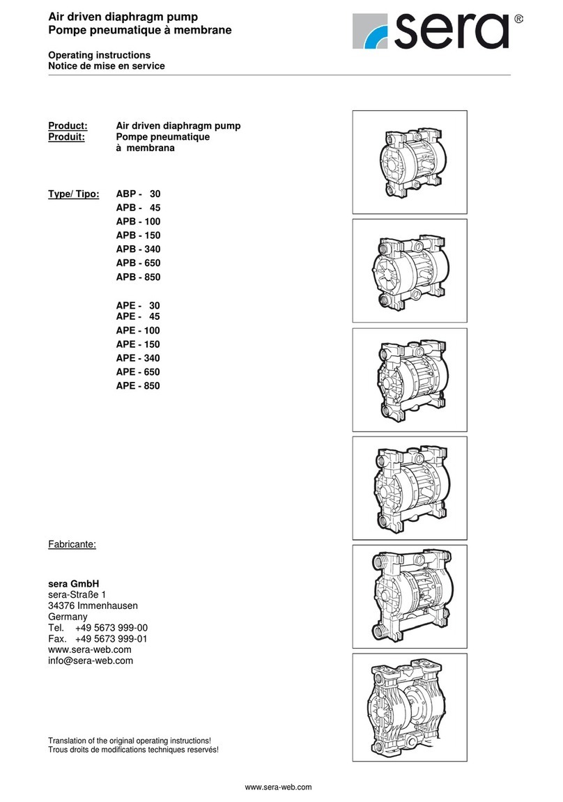
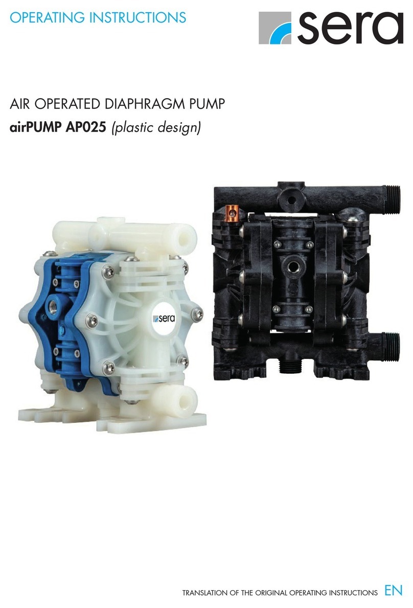
Sera AP05 User manual

OPERATING INSTRUCTIONS
TRANSLATION OF THE ORIGINAL OPERATING INSTRUCTIONS EN
AIR OPERATED DIAPHRAGM PUMP AP05
(plastic design)

airPUMP AP05 (plastic)
2www.sera-web.com

airPUMP AP05 (plastic)
www.sera-web.com 3
TABLE OF CONTENT
IMPORTANT INFORMATION ����������������������������������������������������������������������������������������������������������������4
Export Information ................................................................................................................4
Chemical Reaction Disclaimer.................................................................................................4
Unpacking & Inspection ......................................................................................................... 4
SAFETY PRECAUTIONS������������������������������������������������������������������������������������������������������������������������4
MATERIAL SPECIFICATION �������������������������������������������������������������������������������������������������������������������7
Material Profiles....................................................................................................................7
DimensIons...........................................................................................................................8
Characteristic curves .............................................................................................................8
Performance data .................................................................................................................9
INSTALLATION/OPERATION ����������������������������������������������������������������������������������������������������������������9
Installation Drawing .............................................................................................................. 9
installation / Start up...........................................................................................................10
Troubleshooting Tips and Suggestions.................................................................................... 11
MAINTENANCE ��������������������������������������������������������������������������������������������������������������������������������12
Recommended tools for servicing pump .................................................................................12
Wet End Servicing (Installing Wet End Kit)..............................................................................12
Disassembly ..................................................................................................................12
Mounting ......................................................................................................................14
Air End Servicing (Installing Air End Kit)................................................................................. 16
Shaft, Bushing and O-ring Replacement ............................................................................17
Air Valve O-Ring Replacement .........................................................................................18
Valve and Muffler Gasket Replacement ............................................................................. 19
Replacement Air Valve Kit Installation ..............................................................................20
Exploded View and Spare Parts List.......................................................................................20
CLEARENCE CERTIFICATE �������������������������������������������������������������������������������������������������������������������24
EC DECLARATION OF CONFORMITY��������������������������������������������������������������������������������������������������25

airPUMP AP05 (plastic)
4www.sera-web.com
IMPORTANT INFORMATION
SAFETY PRECAUTIONS
Export Information
Chemical Reaction Disclaimer
Unpacking & Inspection
U.S. Export Administration Regulations, pursuant to ECCN 2B350, prohibit the export or re-export to certain enumerated
countries of air operated double diaphragm pumps in which all wetted materials are constructed from fluoropolymers without
first apply-ing for and obtaining a license from the U.S. Bureau of Industry and Security(BIS). This affects all sera airPUMP
pumps constructed from PVDF with PTFE balls and diaphragms. Please
The user must exercise primary responsibility in selecting the product’s materials of construction which are compatible with the
fluid(s) that come(s) in contact with the product. The user may consult a manufacturer’s representative/distributor agent to seek
a recommendation of the product’s material of construction that offers the optimum available chemical compatibility.
However neither manufacturer nor agent shall be liable for product damage or failure, injuries, or any other damage or loss
arising out of a reaction, interaction or any chemical effect that occurs between the materials of the product’s construction and
fluids that come into contact with the product’s components.
Unpack the pump and examine for any signs of shipping damage.
If damage is detected, save the packaging and notify the carrier immediately.
To install the pump, follow the installation instructions provided.
WARNING
sera airPUMPs maximum temperature limits are based upon the material’s mechanical stress only. Maximum temperature is
ap-plication dependent. Consult a chemical resistance guide or the chemical manufacturer for chemical compatibility and
temperature limits.
WARNING
Chemical Hazard. This pump is used for transferring many types of potentially dangerous chemicals. Always wear pro-
tec-tive clothing, eye protection and follow standard safety procedures when handling corrosive or personally harmful
materials. Proper procedures should be followed for draining and decontaminating the pump before disassembly and
inspection of the pump. There may be small quantities of chemicals present during inspection.
EXPLOSION HAZARD
sera airPUMP with standard materials of construction should not be used with halogenated hydrocarbons. Halogenated
hydrocarbon solvents can cause explosion when used with aluminum components in a closed (pressurized) system. sera
airPUMPs with standard materials of construction contain aluminum components and will be affected by halogenated
hydrocarbon solvents.
1-1-1 Trichloroethane and Methylene Chloride are the most common halogenated hydrocarbons. However, other haloge-
nated hydrocarbon solvents are suspect if used either as part of paint or adhesive formulation, or for clean-up flushing.
For applications that may involve halogenated hydrocarbons, contact sera to discuss the availability of alternative pump
materials of construction.

airPUMP AP05 (plastic)
www.sera-web.com 5
WARNING
Hot surfaces. sera airPUMPs are capable of handling liquids with temperatures as high as 104ºC (220ºF).
This may cause the outer areas of the pump to become hot as well and could cause burns.
WARNING
For polypropylene or PVDF pumps do not exceed 6.9 bar (100 psig) air supply and 8.3 bar (120 psig) for
aluminum and stainless steel.
WARNING
If a diaphragm rupture occurs, material being pumped may be forced out of the air exhaust. Proper care should be taken,
always wear protective clothing, eye protection & follow standard safety procedures.
WARNING
When pumping hazardous liquids, or operating the pump in an enclosed room, it is important to pipe the exhaust air to a
safe area.
WARNING
Pump exhaust may be loud and contain particles. Wear appropriate ear and eye protection. In the event of a diaphragm
rupture material can be forced out of the air exhaust muffler. If product is hazardous or toxic, pipe exhaust to appropriate
safe area.
CAUTION
Before attaching air supply to pump to make sure all airline debris is clear. It is recommended to use a
minimum 5µ (micron) air filter before the air valve.
CAUTION
Do not over-tighten the air inlet fitting or muffler. Too much torque could damage the air valve or muffler plate.

airPUMP AP05 (plastic)
6www.sera-web.com
CAUTION
If pump is used with materials that tend to solidify or settle, the pump should be flushed after each use to prevent damage.
CAUTION
Use only genuine sera replacement parts to assure compatibility and longest service life.
CAUTION
Check the temperature limits for all wetted components when choosing pump materials. See table below.
CAUTION
Before maintenance or repair, close the compressed air line supply valve, bleed the pressure and disconnect air line from
the pump. Discharge line may also be pressurized. Any pressure must be relieved prior to servicing. Remove suction /
discharge lines & drain the pump.

airPUMP AP05 (plastic)
www.sera-web.com 7
MATERIAL SPECIFICATION
MATERIAL PROFILES
Material Chemical composition Description Operating temperature
min� max�
PP Pure Polypropylene Thermoplastic that is resistant to alkali and
strong acids.
0°C
(32°F)
70°C
(158°F)
PVDF Pure Polyvinylidene Fluoride Strong fluoropolymer with excellent chemical
resistance.
-12°C
(10°F)
104°C
(220°F)
Stainless Steel 316 Stainless Steel Excellent chemical resistance, high tensile
and impact strength, abrasion resistant.
Limited by other
materials used
Aluminium ADC 12, LM24, LM25 Moderate chemical resistance with good
impact strength and abrasion resistance.
Limited by other
materials used
Buna Acrylonitrile-butadiene Rubber General purpose elastomer.Resistant to oil,
water, solvent, and hydraulic fluid.
-12°C
(10°F)
88°C
(190°F)
EPDM Ethylene Propylene Diene
Rubber
Good resistance to mild acids, detergents,
alkalis, ketones, and alcohols.
-40°C
(-40°F)
121°C
(250°F)
FKM Fluorocarbon Rubber
Good chemical resistance and high tempe-
rature properties. Resistant to most acids,
aliphatic, aromatic, and halogenated
hydrocarbons, oils, grease, and fuels.
-40°C
(-40°F)
177°C
(350°F)
Neopren Chloroprene Rubber
General purpose elastomer with good resi-
stance to moderate chemicals, oils, grease,
solvents, and some refrigerants.
-18°C
(0°F)
100°C
(212°F)
Santopren
Fully cured EPDM rubber
particles encapsulated in a
polypropylene (PP) matrix
Thermoplastic elastomer with good abrasion
resistance with chemical resistance to a wide
range of solvents and chemicals.
Injection molded with no fabric layer.
-40°C
(-40°F)
107°C
(225°F)
Hytrel Thermoplastic polyester elasto-
mer
Combines resistance and flexibility of elasto-
mers with the strength of plastics. Resistant to
acids, bases, amines, and glycols. Injection
molded with no fabric layer.
-29°C
(-20°F)
104°C
(220°F)
PU Polyester Urethane
Thermoplastic that exhibits excellent abrasi-
on resistance.Injection molded with no fabric
layer.
0°C
(32°F)
66°C
(150°F)
PTFE Polytetrafluoroethylene Chemically inert. Resistant to a wide range
of chemicals.
4°C
(40°F)
107°C
(225°F)
FEP Fluorinated Ethylene Propylene
Similar to PTFE in composition and chemical
resistance. Used to encapsulate FKM o-rings
for superior chemical resistance.
-40°C
(-40°F)
107°C
(225°F)

airPUMP AP05 (plastic)
8www.sera-web.com
DIMENSIONS
CHARACTERISTIC CURVES

airPUMP AP05 (plastic)
www.sera-web.com 9
PERFORMANCE DATA
INSTALLATION DRAWING
INSTALLATION/OPERATION
Air operated diaphragm pump AP05 (Plastic)
Max Flow Rate: 77 Litre/min. (20 gal/m) Suction/Discharge Size: ½“ FBSP or FNPT
Displacement Per Stroke: 0,08 Litre (0.020 gal) Air Inlet/Exhaust Size: ¼“ FNPT / ½“ FNPT
Max Outlet Pressure: 6,9 bar (10-0 psig) Air Consumption @ 6,9 bar: 51 Nm³/h (30 sfcm)
Max Particle Size: 0,7 bar (10 psig) Max Material Inlet Pressure: 8,3 bar (120 psig)
Noise Level: 4,7 mm (0.19“) Max Air Inlet Pressure: 72,1 dB(A)
Max Suction Lift (Water) dry:
wet:
2,7 mWC (9 ft.)
8,8 mWC (29 ft.) Weight: PP:
PVDF:
3,8 kg (8.3 lbs)
5,4 kg (11.9 lbs)
Shut off valve
Shut off valve
Shut off valve
Drain valve
flexible connection
flexible connection
DISCHARGE
SUCTION
Pressure gauge
Compound vacuum/
Pressure gauge
Pulsation damper
INLET
air supply
Air filter Air regulator
flexible connection
at air valve inlet
sera airPump

airPUMP AP05 (plastic)
10 www.sera-web.com
INSTALLATION / START UP
Installation and Start up
Install the pump in a vertical position or it may not prime properly. Pump should be located as close to the product being
pumped as possible. Suction line length should be as short as possible and limit the number of fittings. Suction line di-ameter
should not be reduced smaller than the suction diameter of the pump. When using rigid pipe run short sections of flexible hose
or flexible connections between the pump & piping. Secure the pump to a suitable surface.
Air Supply
Connect the pump air inlet to an air supply with sufficient capacity to achieve desired performance. A pressure regulating
valve should be installed to insure air supply pressure does not exceed recommended limits.
Fasteners
Re-torque all fasteners before operation. Creep of housing and gasket materials may cause fasteners to loosen. Re-torque all
fasteners to the torque specifications listed on the exploded view drawing in this manual.
Air Inlet & Priming
Pump will start to operate as soon as the shut-off valve is opened. It is recommended to open the shut-off valve slowly at first.
Once the pump primes; the shut-off valve can be opened additionally to increase the pump’s flow. If the pump is oper-ating
but not pumping any liquid see the troubleshooting section for tips & suggestions.
Accessories
Surge suppressors, spill stops & filter regulators are available and should be used with sera airPUMP.
Air Valve Lubrication
No lubrication is required for the air distribution system.

airPUMP AP05 (plastic)
www.sera-web.com 11
TROUBLESHOOTING TIPS AND SUGGESTIONS
PUMP WILL NOT START OR CYCLEL:
■Blocked liquid pipe or hose - Clean out or replace
■Clogged liquid chamber - Remove debris
■Diaphragm shaft bushing / o-ring leak - Replace o-rings
■Air valve carrier not shifting - Inspect, clean, re-oil with 10 wt. air tool oil. (aluminum air valve)
■Air valve carrier not shifting - Inspect, replace seals (polypropylene air valve)
ERRATIC CYCLING:
■Diaphragm failure - Replace diaphragm
■Valve ball not seating properly, worn or damaged – Inspect, remove debris or replace
■Leak in suction line - Inspect, repair or replace
■Diaphragm shaft bushing / o-ring leak - Replace o-rings
■Air valve carrier not shifting - Inspect, clean, re-oil with 10 wt. air tool oil. (aluminum air valve)
■Air valve carrier not shifting - Inspect, replace seals (polypropylene air valve)
■Over lubrication in air valve - Inspect, degrease, reuse. Adjust lubrication
■Excess moisture in air valve – Inspect, dry, reuse. Consider installing an air dryer
■For aluminum air valves, worn carrier or valve bore – measure carrier and valve bore, diametrical clearance should be
between 0,05 - 0,088mm. Replace worn components as needed
■For plastic air valves, worn carrier seals – replace carrier seals if there is no longer interference between seals and valve
bore
PUMP CYCLES BUT WILL NOT PUMP:
■Too much suction lift - Reduce suction lift or fill liquid chambers with liquid
■Leak in suction line - Inspect, repair or replace
■Valve ball not seating properly, worn or damaged - Inspect, remove debris or replace
■Clogged suction pipe or hose - Inspect & clear
■Clogged strainer if used - Inspect & clear
■Diaphragm failure - Replace diaphragm
PUMPED LIQUID RELEASED FROM AIR EXHAUST:
■Diaphragm failure - Replace diaphragm
■Outer plate unthreading - Tighten & re-torque

airPUMP AP05 (plastic)
12 www.sera-web.com
MAINTENANCE
DISASSEMBLY
Recommended tools for servicing pump
■Box wrench (10mm and 13mm)
■Socket wrenches (20mm (2x))
■Snap ring pliers
■Hex wrenches (3mm, 5mm and 6mm)
■O-Ring pick
■Torque wrench
Wet End Servicing (Installing Wet End Kit)
■Relieve airline pressure and fluid line pressures before conducting maintenance.
■The pump can be drained by turning it upside down and allowing fluid to drain into an appropriate container. Use proper
safety equipment when conducting maintenance as internal components may still contain the pumped media.
■Lubricate all stainless steel to stainless steel fasteners to prevent galling.
■Torque values listed in the back of this manual (see page 23).
2)
he discharge seat o-rings, valve seats and valve balls
(items 13, 14, 15 &16) can now be accessed and
replaced if needed.
1)
Remove the four discharge manifold bolts (item 11) from
the discharge manifold (item 32) using a 10mm wrench.

airPUMP AP05 (plastic)
www.sera-web.com 13
3)
Repeat the above steps for the suction
manifold (item12). The seat o-rings, valve
seats and valve balls (items 13, 14, 15
& 16) are located in the liquid chambers
(item 18).
4)
Remove both liquid chambers by remo-
ving the (6) bolts (items 17) on each
liquid chamber using a 13mm (or ½“)
wrench. Inspect and replace diaphragms
if needed.
5)
To remove the diaphragms (items
20/ 21), begin by loosening the (2)
outer plates (item 19) using 2-20mm
wrenches. Use 6-sided sockets or
wrenches to prevent damage to the hex
portion of the outer plate.
6)
Remove the outer plate, diaphragm(s), and inner plate (items 19, 20/21 & 22) from the side that is loosened. Pull or push the
shaft (item 27) and remaining plates and diaphragms out of the center section. If pulling, it may be easier to grip the dia-
phragm if it is inverted.
7)
To remove the remaining diaphragm(s) (items 20/21) and plates
(items 19 & 22) from the shaft (item 27), place the shaft in a vise
fitted with soft jaws. Using a 6-sided 20mm wrench, remove the
remaining diaphragm(s) and plates. Soft jaws are required to pre-
vent damaging the shaft. A damaged shaft will result in accelerated
o-ring wear. Jaws can be fitted with wood, plastic, rubber, or other
soft material to prevent shaft damage.
After performing required maintenance, the pump can be reassembled. The pump can also be reassembled using the disas-
sembly instructions in the reverse order as listed above. For detailed assembly instructions, follow steps „Mounting“ instructions
on next page.

airPUMP AP05 (plastic)
14 www.sera-web.com
1)
Slide the center hole of one diaphragm (item 21) over the molded
in bolt of an outer plate (item 19). The air side of the diaphragm is
labeled and should face away from the plastic portion of the outer
plate. If the pump is fitted with PTFE diaphragms (item 20), first
place a PTFE diaphragm over the molded in bolt of the outer plate
(item 19). Then place the backup diaphragm (item 21) on the outer
plate. The shape of the PTFE diaphragm and back up dia-phragm
should roughly conform to one another. See the exploded view
drawing for proper orientation.
MOUNTING
3)
Apply a couple drops of a medium strength thread
locker, such as Loctite® 246, to the molded in outer
plate bolt (item 19). Thread the shaft (item 27) onto the
molded in bolt until it is snug to the flat back side of the
inner plate (item 22).
5)
Push the shaft (item 27) through the center of the shaft
bushing (item 24). It is normal for this to be a tight fit,
especially if the shaft and shaft o-rings (item 26) are in
good condition.
2)
Place the inner plate (item 22) over the molded in bolt.
Ensure the round recess in the plate faces the dia-
phragm (item 21).
Diaphragms are shown inverted to ease assembly.
4)
The shaft (item 27) and shaft o-rings (item 26) should
retain the lubricant that was factory applied. If they ap-
pear dry, apply a light coat of lithium thick-ened grease.
Avoid over lubrication as it can cause decreased perfor-
mance of the air distribution system.

airPUMP AP05 (plastic)
www.sera-web.com 15
7)
Tighten and torque the outer plates (item 19). If the
pump is fitted with PTFE diaphragms (item 20), it is
necessary to restrict their ability to rotate when tigh-
tening the outer plates. This can be done by threading
the liquid chamber bolts (item 17) through the PTFE
diaphragm holes and into the center section (item 28)
on each side. This will ensure that the PTFE diaphragm
does not obstruct the bolts ability to thread into the
center section when the liquid chambers are installed.
Remove these bolts once the outer plates are torqued.
9)
Flip the pump upside down and drop the suction valve
balls (item 16) into the liquid chamber (item 18) ball
cages.
Note: When installing polytetrafluoroethylene (PTFE) diaphragms, it is important to tighten outer plates simultaneously (turning
in opposite directions) to ensure tight fit.
6)
The other diaphragm(s) (items 20/21) and inner/
outer plates (items 19 & 22) can be installed onto the
opposite end of the shaft (item 27). It may be easier to
thread the molded in bolt into the shaft if the diaphrag-
m(s) is inverted on one or both sides. This can be done
by hand.
8)
Install the liquid chambers (item 18) by placing one
side over the diaphragm. Start all bolts (item 17) before
tightening and torqueing. Torque all fasteners in a star
pattern. Repeat to install the second liquid chamber.
Ensure both chambers are orientated the same and that
the inlet and outlet ports are vertical when facing the
front of the pump as shown.

airPUMP AP05 (plastic)
16 www.sera-web.com
10)
Place the larger valve seat o-rings (item 15) into the seat bores of the liquid chambers followed by the valve seats (item 14).
Install the two smaller o-rings (item 13) into the face grooves in the valve seats. The seats are to be orientated so that the edge
groove on the seat accepts the larger o-ring.
12)
Stand the pump upright onto the suction manifold feet
(item 12). Place the small valve seat o-rings (item 13) on
the flat faces of the liquid chambers (item 18) followed
by the valve seats (item 14) on the o-rings. Place the val-
ve balls (item 16) onto the valve seats. The larger valve
seat o-rings (item 15) can be installed into the discharge
manifold (item 32). Place the manifold atop the pump,
over the components that are on top of the liquid cham-
bers. Tighten and torque the discharge manifold bolts in
an “X” pattern.
11)
Check that the top of the seat (item 14) is about flush
with the liquid chamber. Place the suction manifold
(item 12) atop the pump. Tighten and torque the suction
manifold bolts (item 11) in an “X” pattern.
AIR END SERVICING (INSTALLING AIR END KIT)
■Follow steps 1 – 6 in the Wet End Servicing disassembly section to access the shaft bushing (item 24) and o-rings (items 23
& 26), then follow steps below.

airPUMP AP05 (plastic)
www.sera-web.com 17
2)
Use the supplied grease packets to lightly grease the
OD and ID o-rings (items 23 & 26) that come preinstal-
led in the new shaft bushing supplied in air end kits.
Insert the shaft bushing into the center section (item 28)
and reinstall the retaining ring.
1)
Remove the shaft bushing retaining ring (item 25) and
push the shaft bushing out of the center section.
SHAFT, BUSHING AND O-RING REPLACEMENT
■After determining if the condition of the shaft is acceptable, follow steps 5 – 12 in the Wet End Servicing – Wet End Reas-
sembly section to rebuild the rest of the pump.
3)
Inspect the shaft (item 27) for damage. It is common
for shafts to become grooved during service. Grooving
is normally caused by carbonized oil and/or abrasive
foreign material getting trapped between the seal and
the shaft. Over time, deep grooves can form in the shaft.
When that occurs, it is recommended that the shaft be
replaced.

airPUMP AP05 (plastic)
18 www.sera-web.com
1)
Aluminum Air Valve
To replace the valve cap o-rings (item 5), remove the
(3) button head cap screws (item 7) using a 3mm hex
wrench.
2)
Aluminum Air Valve
Remove and replace o-ring (item 5). Install cap (item
6), tighten, and torque the valve cap screws (item 7).
Repeat for the remaining cap.
1)
Plastic Air Valve
To replace the valve cap o-ring remove the retaining
ring (item 8), then unthread the valve cap (item 6) using
a 6mm hex wrench.
2)
Plastic Air Valve
Remove and replace o-ring (item 5). Install cap (item 6)
and tighten until groove for the retaining ring is visible.
AIR VALVE O-RING REPLACEMENT

airPUMP AP05 (plastic)
www.sera-web.com 19
2)
Pull the valve body and gasket (items 3 & 30) off the
front of the center section (item 28) and the muffler plate
gasket, muffler plate and muffler (items 29, 31 & 33) off
the back.
1)
Remove the valve body (item 3) by removing the four
socket head cap screws (item 1) that attach the valve
body to the muffler plate (item 31) with a 5mm hex
wrench.
VALVE AND MUFFLER GASKET REPLACEMENT
3)
Place the new gasket (item 30) on the air valve (item 3) and ensure the slots in the gasket align with the slots in the air valve
and valve plate (item 10).
Air Valve Slide, Plate & Gasket Orientation: If the valve plate (item 10) and slide valve (item 9) are removed, ensure they
are installed in the proper orientation. The flat face of the slide valve sits in the pocket of the valve carrier (item 4) so that the
square cut out on the slide valve faces the smooth polished side of the valve plate.
3)
Insert the four cap screws & washers (1
& 2) through the valve body and gasket
(3 & 30) and place onto the center secti-
on (item 28). Ensure the slide valve and
valve plate (9 & 10) are in place and the
valve sits flat on the center section.
4)
Place the muffler gasket (item 29) over
the four cap screws (item 1) on the
back side of the center section (item 28)
followed by the muffler plate and muffler
(items 31 & 33).
5)
Tighten and torque the four cap screws
into the muffler plate.

airPUMP AP05 (plastic)
20 www.sera-web.com
REPLACEMENT AIR VALVE KIT INSTALLATION
EXPLODED VIEW AND SPARE PARTS LIST
■1) Remove the valve that is to be replaced by removing the (4) socket head cap screws with a 5mm hex wrench that
attaches the valve body to the muffler plate.
■2) Save the (4) cap screws, (4) lock washers, muffler plate, and muffler. All other valve components can be
discarded.
■3) Remove the packing tape that holds the air valve components in place during shipping.
■Follow steps 3 – 6 in the Valve and Muffler Gaskets section of Air End Servicing above.
Pos� Description Material Part-No� Qty� Set
1 CAP SCREW, SOCKET HD M6X1.0 X 110MM SSTL 109519 4 ---
2 WASHER, LOCK M6 HIGH-COLLAR SSTL 109517 4 ---
3 VALVE BODY SEE AIR VALVE TABLES V1/V2
4 VALVE CARRIER SEE AIR VALVE TABLES V1/V2
5 VALVE CAP O-RING SEE AIR VALVE TABLES A1/A2/V1/V2
6 VALVE CAP SEE AIR VALVE TABLES V1/V2
7 CAP SCREW, SOCKET HD M4X0.7 X 10MM SEE AIR VALVE TABLES V2
8 RETAINING RING, HO-81 SSTL SEE AIR VALVE TABLES V1
9 SLIDE VALVE 109257 1 V1/V2
10 VALVE PLATE 109261 1 V1/V2
11 CAP SCREW, HEX HD FLNG M6X1.0 X 35MM SSTL 109505 8 ---
12 MANIFOLD, SUCTION PP SEE MANIFOLD TABLES ---
PVDF
Table of contents
Other Sera Water Pump manuals

Sera
Sera R 204.1 Series User manual

Sera
Sera iSTEP S 20 User manual

Sera
Sera airPUMP AP025 User manual

Sera
Sera PP 2500 Specification sheet

Sera
Sera C 409.2 Series User manual

Sera
Sera 409.2 Series User manual

Sera
Sera 409.2 ML Series User manual

Sera
Sera C 409.2 Series User manual

Sera
Sera ABP-30 User manual

Sera
Sera M 409.2 Series User manual
Popular Water Pump manuals by other brands

GÜDE
GÜDE HWW 900 GC Translation of the original instructions

Bosch
Bosch Rexroth 63 Series instruction manual

Sealey
Sealey TP6918 instructions

Putzmeister
Putzmeister BSA 1006 D5 operating instructions

OLIJU
OLIJU SFI Installation and operation instructions

BRINKMANN PUMPS
BRINKMANN PUMPS BE8082 operating instructions