SERGE GTS User manual

SERGE
GTS
FOR EURORACK
OUT
FALLRISE
SERGE MODULAR
◄ IN
OUT
FALLRISE
IN ►
MAX
MIN
SUM
1V/O 1V/O
GTS
BOTH
FALLAUX2
OUTEND
TRIG
IN
ENDOUT
TRIG
IN
L R
RISE FALL AUX1
CYCLE CYCLE
BOTH
RISE
USER MANUAL
V1.0
RANDOM*SOURCE

SERGE-MODULAR.COM
SERGE MODULAR
2
GTS
Installation ........................................................ 3
Overview ......................................................... 3
The Slope Generators................................................ 4
Serge GTS - Basic Slope Operation ..................................... 5
The Middle Section.................................................. 7
MIXER (SUM) ...................................................... 8
MAX and MIN ...................................................... 9
Patch Ideas ...................................................... 10

SERGE-MODULAR.COM
SERGE MODULAR
3
GTS
Installation
Always turn the eurorack case off and unplug the power cord before plugging or unplugging any eurorack power
cable. Do not touch any electrical terminals when attaching any eurorack power (bus board) cables.
The Serge GTS is an electronic music module requiring about 85mA of +12VDC and 80 mA of -12VDC regulated
voltages and an appropriate power connector to operate. It must be properly installed into a eurorack format
modular synthesizer system case.
POWER YOUR CASE OFF before installing the module. Please use the power cable provided to connect the small
end of the power cable to the module: RED STRIPE to “-12V”, as indicated on the back of the module. Carefully
install and secure the module in your case. Power on, and ip the CYCLE switches to the DOWN position. Turn
all the RATE knobs (RISE, FALL) to center position theYou should see an LED ashing on each side. If either side
seems constantly ON or OFF, turn the RATE knob to the center position or slightly below to see each side cycling.
Your module should be ready to go now :-)
Please beware: Powering the module on anything more (or less) than +/-12V is not recommended and may
damage the module. Feeding any of the inputs (or outputs) with voltages outside a +/-12V range may damage the
module. This type of damage is not covered under warranty.
Overview
For the GTS, Serge has completely redesigned his famous Serge Dual Universal Slope Generator (DUSG) - with a
new core, temperature compensation and optimized for speed and tracking.
The rst version of the DUSG which was part of the 3rd generation of Serge symthesizers came out in 1976 and
became one of the mose versatile and iconic Serge modules. The original design, which was copied in the popular
Maths module, was primarily intended for control voltages and - due to the low frequency range - of limited use
for audio.
The GTS can still be used for CV - due to the enormous range, cycles of an hour or more are possible - and still
provides all the functions of the original version. However, it now also provides exceptional audio performance:
transient rise and fall times as fast as 12µs and a maximum cycle speed of about 27kHz. In addition, 1V/Octave
inputs have been added, providing exceptional tracking when the waveform is set to sawtooth (RISE knob
turned all the way up), turning the GTS into a complex oscillator.
As its predecessor, the GTS is still the combination of two identical slope generators. However, these have
been combined with a CV processor / mixer as well as a Serge Peak & Trough (Minimum and Maximum
functions).
SERGE-MODULAR.COM
SERGE MODULAR
4
The Slope Generators
The two slope generators in the GTS are identical. For more clarity, only the left side is shown here with numbers:
OUT
FALLRISE
SERGE MODULAR
◄ IN
OUT
FALLRISE
IN ►
MAX
MIN
SUM
1V/O 1V/O
GTS
BOTH
FALLAUX2
OUTEND
TRIG
IN
ENDOUT
TRIG
IN
L R
RISE FALL AUX1
CYCLE CYCLE
BOTH
RISE
1
MAIN OUT
2
AC OUT
3
END OUT
5
PULSE OUT
4
INPUT (LEFT)
6
CYCLE SW
10
CV RISE
12
RISE AV
14
RISE RATE
7
1V/OCT 8
TRIGGER IN
11
CV FALL
9
CV BOTH
13
FALL AV
15
FALL RATE

SERGE-MODULAR.COM
SERGE MODULAR
5
Serge GTS - Basic Slope Operation
1. MAIN OUT In CYCLE mode (switch down or CYCLE OUT connected to IN), the MAIN OUT provides
a triangular waveform whose symmetry can be adjusted from sawtooth to triangle to ramp
using the RISE (14) and FALL (15) knobs. Range is 0-5V when Cycling. Otherwise, this
output tries to follow the amplitude of the input (4) with the speed set by RISE and FALL.
Set the waveform to sawtooth (Rise = max, Fall at about 2 o’clock) to achieve the
best tracking of the 1V/Octave input (up to > 2.5kHz).
The LED next to the MAIN OUT visually indicates the voltage level.
2. BIPOLAR OUT Inverted version of the MAIN OUT that has an AC range of appr. -2.5V to 2.5V when Cycling.
MAIN OUT (yellow) and BIPOLAR OUT (purple)
3. END OUT Logic signal - goes high et the end of the fall (and stays there for about 80% of the rise time).
Pulse width depends on RISE and FALL settings - pulse width is extremely short when Rise
is fastest (knob at max). Patched back to TRIG IN starts the Cycle (this is what the switch
does).
4. INPUT Signal Input: Direct Coupled input to the GTS. Use for Lag, Portamento, (pseudo-)ltering,
ASR (Attack Sustain Release) type envelopes. Also input to the middle section when not
Cycling (CV-Processor, MAX, MIN).
5. PULSE OUT Logic signal has a xed duty cycle of about 50-60%, i.e. does not get as thin as the END
OUT. When the MAIN OUT is set to sawtooth for oscillator use / best tracking, this output
provides an alternative (pulse) waveform with the same tracking.
6. CYCLE SWITCH connects TRIG IN to GATE OUT and saves you a patch cord.
7. 1V/OCT CV input calibrated for use of the GTS as sawtooth oscillator. When the GTS is set to
CYCLE and RISE knob (14) is turned all the way up (fastest rise) and FALL (15) is set
so that the base frequency - no CV applied - is set to (roughly) C1 (32.7 Hz), best tracking is
achieved: the pitch of the GTS will follow the input over 6 octaves up to more than 2.5
kHz. Chaning the waveform to anything else (e.g. triangle wave) will affect RISE and FALL,
but not provide good tracking.

SERGE-MODULAR.COM
SERGE MODULAR
6
8. TRIGGER N A logic signal (gate or trigger) sent to this input triggers the circuit (regardless of what’s
happening at the INPUT (4) and generates an envelope at the MAIN OUT (1), the shape of
which is dened by the RISE and FALL settings (and any CV applied). Uses include Envelope
generation, Pulse Delay, Clock Division etc.
9. CV BOTH Linear control signal input for RISE and FALL equally. Control voltage applied here is as if the
same had been sent to both 10 and 11 individually.
10. CV RISE Linear control signal input for RISE. Positive control voltage (CV) makes the rise faster,
negative slows the rise time down (taking into account the RISE RATE (14) setting. Patch the
main out back here for exponential or logarithmic rise shapes.
11. CV FALL Linear control signal input for FALL. Positive control voltage (CV) makes the fall faster,
negative extends the fall duration (taking into account the FALL RATE (14) setting. Patch the
main out back here for exponential or logarithmic fall shapes.
12. RISE AV Attenuverter Control for the rising slope: provides for scaling, attenuation, amplication and
inversion of the CV signal(s) sent into CV BOTH (9) and/or CV RISE )10).
13. FALL AV Attenuverter Control for the falling slope: provides for scaling, attenuation, amplication and
inversion of the CV signal(s) sent into CV BOTH (9) and/or CV FALL (10). Patch the main out
back here for exponential or logarithmic rise shapes.
14. RISE RATE Knob controlling the speed of the RISE, i.e. sets the time it takes for the MAIN OUT to
ramp up. Clockwise rotation increases speed / frequency. Turn all the way up to max for a
supercrisp sawtooth and best tracking. Knob cover an enormous range of more than an
hour to appr. 12µs.
15. FALL RATE Knob controlling the speed of the FALL, i.e. sets the time it takes for the MAIN OUT to ramp
up. Clockwise rotation increases speed / frequency. Knob cover an enormous range of
more than an hour to appr. 12µs.
The highest frequency is about 27kHz.

SERGE-MODULAR.COM
SERGE MODULAR
7
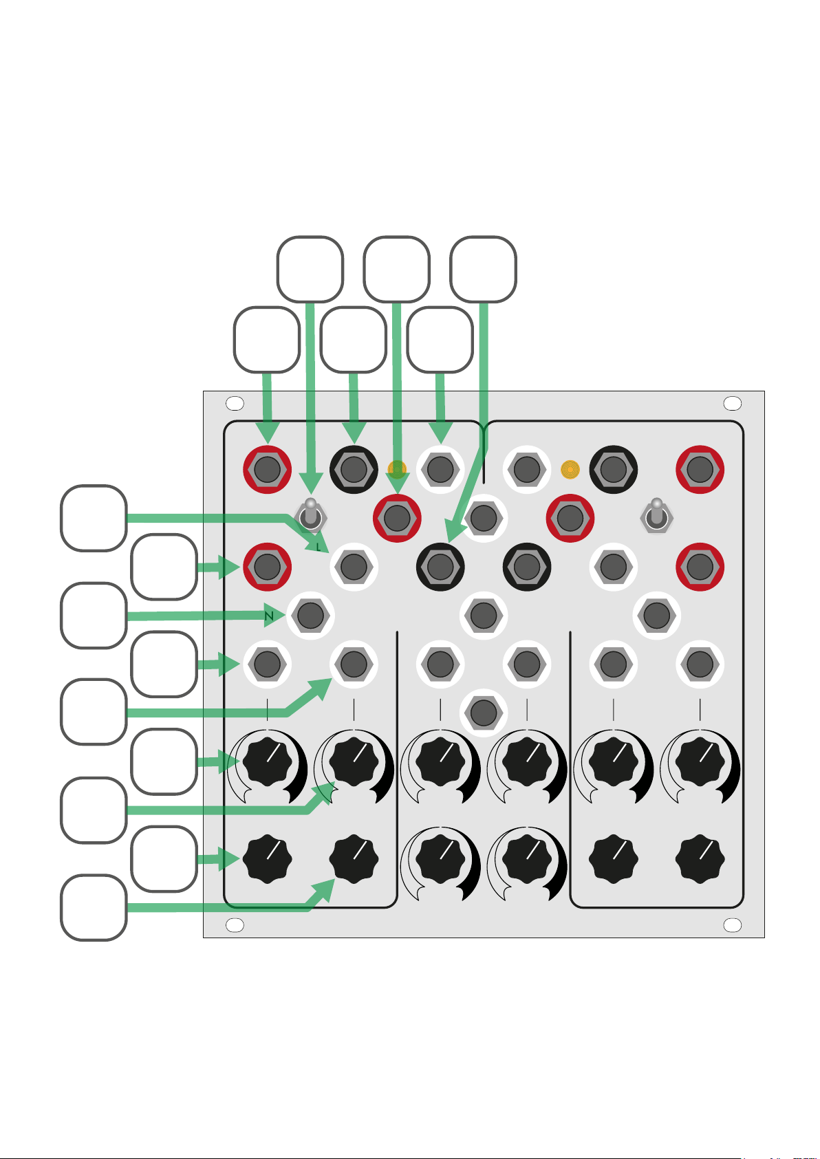
The Middle Section
Both slope generators meet in the middle section: a 4 channel processor / mixer where 2 channels are hardwired
to the MAIN OUTs and a Maximum and Minimum function.
OUT
FALL
RISE
SERGE MODULAR
◄ IN
OUT
FALL
RISE
IN ►
MAX
MIN
SUM
1V/O
1V/O
GTS
BOTH
FALL
AUX2
OUT
END
TRIG
IN
END
OUT
TRIG
IN
L R
RISE
FALL
AUX1
CYCLE
CYCLE
BOTH
RISE
16
SUM OUT
20
MIN OUT
17
MAX OUT
19
AUX2 IN
22
AUX2 IN
24
RIGHT AV
18
AUX1 IN
21
AUX1 AV
23
LEFT AV
SERGE-MODULAR.COM
SERGE MODULAR
8
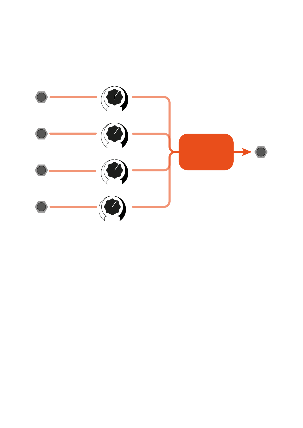
MIXER (SUM)
A 4 channel CV (or audio) processor / mixer combines the 2 MAIN OUTs - prewired as channels L(eft) and
R(ight) - plus 2 AUX inputs into the SUM OUT (16). Each channel has an attenuverter, i.e. turning the knob to the
left inverts the signal.
NORMALIZED
TO +6V
LEFT
MAIN OUT
AUX 1
IN
AUX 2
IN
RIGHT
MAIN OUT
L
R
AUX1
AUX2
MIXER
SUM OUT
16. SUM OUT Sum of the voltages of the 4 channels, each as scaled or inverted with the relevant attenuverter
control.
18. AUX1 IN Direct Coupled AUX 1 Signal Input. Routed via Attenuverter to SUM and MAX.
19. AUX2 IN Direct Coupled AUX 1 Signal Input. Routed via Attenuverter to SUM and MIN. Normalized to
+6V for generation of voltage offsets.
21. AUX1 AV Attenuverter Control for AUX1: provides for scaling, attenuation, amplication and inversion
of the CV signal(s) sent into AUX1 input (18). Used for SUM and MAX function.
22. AUX2 AV Attenuverter Control for AUX2: provides for scaling, attenuation, amplication and inversion
of the CV signal(s) sent into AUX2 input (19). Used for SUM and MIN function.
23. LEFT AV Attenuverter Control for LEFT channel, i.e. the MAIN OUT of the left side. The processed
signal is routed into the SUM output. Not used for MAX or MIN.
24. RIGHT AV Attenuverter Control for RIGHT channel, i.e. the MAIN OUT of the right side. The processed
signal is routed into the SUM output. Not used for MAX or MIN.
SERGE-MODULAR.COM
SERGE MODULAR
9
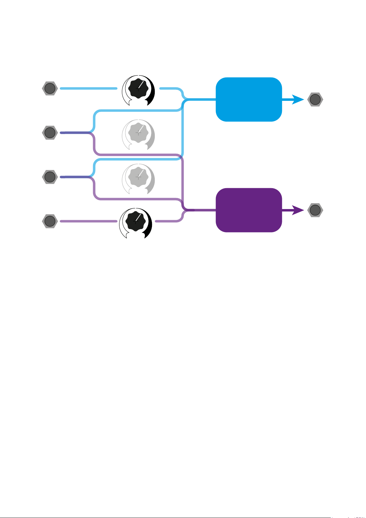
MAX and MIN
NORMALIZED
TO +6V
LEFT
MAIN OUT
AUX 1
IN
AUX 2
IN
RIGHT
MAIN OUT
L
R
AUX1
AUX2
MAXIMUM
MAX OUT
MINIMUM
MIN OUT
17. MAX OUT Compares the MAIN OUTs and AUX1 and provide the largest value of these waveforms at
any time.
20. MIN OUT Compare the MAIN OUTs and AUX2 and provide the smallest value of these waveforms.
AUX2 IN (19) is normalized to 6V and therefore acts as an upper threshold in no cable is
plugged into AUX2. So it’s important to turn the AUX2 knob (22) all the way up to get
a full signal when nothing is patched into AUX 2 IN (19).

SERGE-MODULAR.COM
SERGE MODULAR
10
Patch Ideas
Sync’d VCO
Using both sides combined as one tracking oscillator.
• CYLCE both sides of the GTO.
• Set SMPL switch to center (“free”).
• Keyboard 1V/OCT left and right 1V/OCT of the GTO.
• Adjust the RATE of the left side to tune the left side to be one octave (or 2 octaves, or 5 semitones or ...)
higher than the right side.
• Right CYCLE out left SYNC input.
• Listen to left OUT or red COUPLER.
Metallizing VCA
Use a PCO or NTO (or another GTO) as a sound source, the right side of GTO as lter / VCA, however, scrambled
by the left GTO:
• SAW (or PULSE, TRI) GTO right side IN.
• CYLCE left side of GTO
• CYCLE out (left) RUN on the right
• Keyboard 1V/OCT PCO 1V/OCT and left GTO 1V/OCT
• Keyboard GATE OUT ExtADSR (or DSG) for Envelope
• ExtADSR OUT VC RATE of right GTO, VC RATE attenuverter fully CW
• right GTO: Rate knob at about 40%
Variations:
1. SYNC: Send PULSE OUT of PCO to GTO SYNC input.
2. (b) Send 2nd output of PCO to 1V/Oct of right GTO
3. (c) Send envelope from ExtADRS also to VC-RATE of GTO (left), VC-RATE attenuverter near center.
Geometric Waveshapes:
• Send a SAW wave from a PCO or NTO or DSG GTO left side SYNC and GTO right side SMPL.
• Keyboard 1V/OCT PCO 1V/OCT and left GTO 1V/OCT
• CYLCE left side of GTO
• Do not CYLCE right side of GTO

SERGE-MODULAR.COM
SERGE MODULAR
11
• CYCLE out (left) IN on the right
• Set SMPL switch to SMPL (top)
• RED Coupler RUN on the right
• Keyboard GATE OUT ExtADSR (or DSG) for Envelope
• ExtADSR OUT VC RATE of right GTO, VC RATE attenuverter fully CW
• Right GTO: Rate knob at about 50%
• Listen to right GTO OUT.
SYNC FM
• CYLCE both sides of the GTO.
• Set SMPL switch to Cycle (center) or INV
• Right OUT left VC RATE (RATE attenuverter set to about 2 p.m.)
• Keyboard 1V/OCT both left and right 1V/OCT (but don’t expect the patch to track!)
• Right CYCLE out SYNC
Variations:
• Send left GATE OUT to RUN and set SMPL switch to SMPL or INV
SYNC DRONE
Again, using both sides combined as one massive oscillator.
• CYLCE both sides of the GTO.
• Left CYCLE RUN
• Right CYCLE out SYNC
• Right CYCLE out right VC RATE
• Set SMPL switch down (“INV”).
• Keyboard 1V/OCT left and right 1V/OCT of the GTO.
• Adjust the RATE of the left side to tune the left side to be one octave (or 2 octaves, or 5 semitones or ...)
higher than the right side.
• Send ADSR or LFO to left VC RATE with VC RATE knob close to center.
• Alternatively, send black COUPLER to left VC RATE with VC RATE knob close to center.
• Use right RATE knob to adjust pitch.
• Listen to left OUT (green) or red COUPLER (orange) - yellow wave is a mix of left OUT and COUPLER:

SERGE-MODULAR.COM
SERGE MODULAR
12
(Version 20 Jan 2024)
SERGE Modular /// Random*Source. All rights reserved.
Table of contents


