2
CA
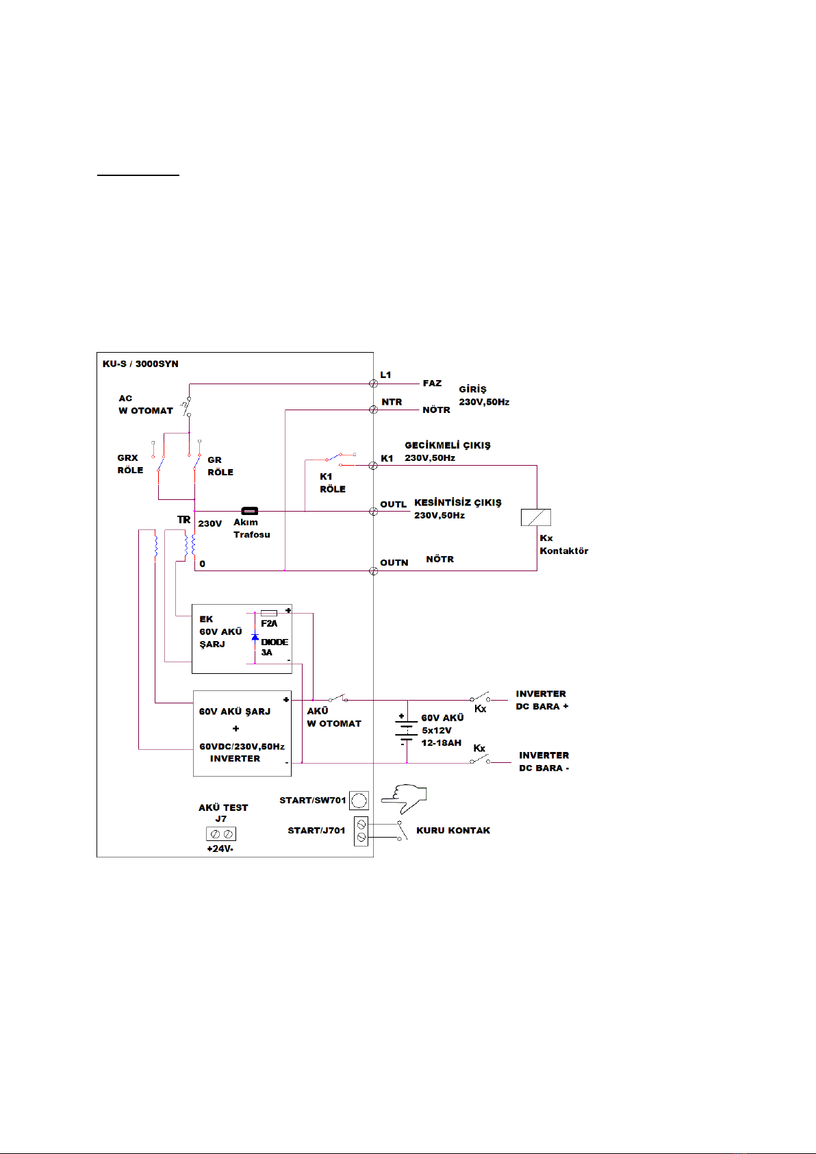
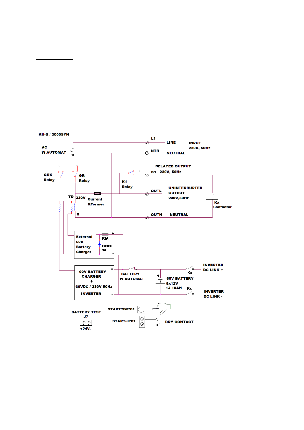
3. There is a W automat circuit breaker on battery circuit for protection of the batteries and for
easy service.
4. The device is fully protected against reverse polarity battery connection.
5. There is a W automat circuit breaker on 220V AC line, for protection and easy service.
6. There is a ‘COLD START’ function.During the waiting time for the ac power to come back,
pushing the start button START(SW701) for 2-3 sec, the device starts without waiting for the L1
phase to come back. This is especially good to make service and maintenance work when ac
power is out or is not available.
A remote parallel pushbutton switch connection terminals START (J701) are also available on
the pcb. There must be only DRY CONTACT connections at START (J701) terminals.
7. The device functions without battery connection, that means the voltage on L1 input is
connected to the OUTL output, even if the batteries are not connected, or discharged
completely to zero.
So the batteries do not cause any additional fault to the operation of the elevator panel. This
improves the realibility of the elevator panel equipped with an emergency evacuation device.
Ofcourse, in this case, the emergency evacuation operation can not be done.
8. For most of the possible faults of the device, the L1 and OUTL terminals stays connected,
and the elevator panel operates. So generally the device does not cause any potential fault
to the operation of the elevator panel.
9. Appling 24V DC to +27- (J7) Terminals gets the UPS into battery test mode while UPS is in
main mode.
By this fuction you can test the batteries periodically.
ATTENTION! A standart UPS does not satisfy item 7 and 8 above. A standart UPS with the batteries
disconnected, does not start when it is connected to 220V AC for the first start. That means the 220V
AC input voltage stays disconnected from the output terminal, and the elevator panel does not function.
4.OPERATION:
1. At the beginning, when L1 phase is OFF, the device is dead, and the contacts are as
shown in the figure.
2. When L1 phase becomes ON, the device starts operation, the relays GR and GRX
becomes ON, OUTL output is connected to L1 input voltage.
3. When L1 phase fails, GR relay becomes OFF, and if the battery is connected, OUTL
continuous to supply the load without any interruption, and the operation duration timing
starts. Operation duration is 300 seconds.
If the battery is not connected, when AC fails, the OUTL fails also, and the devices dies.
When L1 phase comes back, the device starts from the beginning again.
4. After 20 seconds K1 relay becomes ON, for the delayed output.
5. After 300 seconds, the device stops and becomes complete dead. From now on no
current is drawn from the batteries, batteries are saved from discharging.
6. When L1 phase comes back, the device starts operation from the beginning.