Hubbell GAI-TRONICS HUBBCOM GSC User manual

Pub. 42004-551B
G A I - T R O N I C S ®
A H U B B E L L C O M P A N Y
HUBBCOM™
Device Configuration Guide
TA B L E O F CO N T E N T S
GAI-TRONICS 3030 KUTZTOWN RD. READING, PA 19605 USA
610-777-1374 ◼800-492-1212 ◼Fax: 610-796-5954
VISIT WWW.GAI-TRONICS.COM FOR PRODUCT LITERATURE AND MANUALS
Confidentiality Notice.....................................................................................................................3
General Information.......................................................................................................................3
Configuration Tree Structure.........................................................................................................3
Unit Screen......................................................................................................................................5
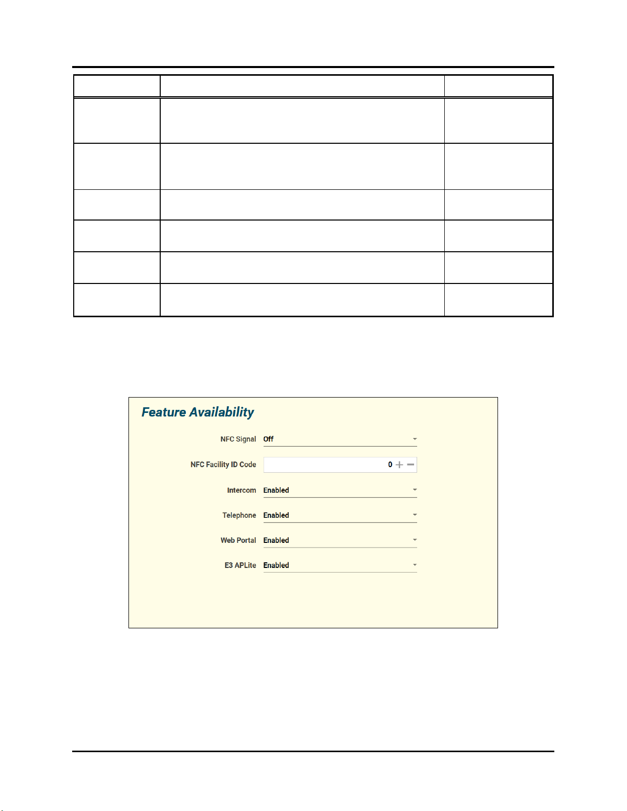
Feature Availability................................................................................................................................8
Network....................................................................................................................................................9
Network—Default LAN ..................................................................................................................... 10
Network—WiFi..................................................................................................................................11
Network—Access Point...................................................................................................................... 12
VLAN .................................................................................................................................................13
VLAN A-H......................................................................................................................................... 14
Intercom.................................................................................................................................................16
Streams................................................................................................................................................17
Mutual Provisioning ...........................................................................................................................22
Discovery Channel.............................................................................................................................. 22
Outputs................................................................................................................................................ 23
Phone......................................................................................................................................................23
SIP Registrar 1–3................................................................................................................................24
SIP Contacts........................................................................................................................................26
SIP Advanced Features.......................................................................................................................28
Point to Point.........................................................................................................................................29
HUBBCOM GSC Devices..................................................................................................................29
HUBBCOM GRC Devices.................................................................................................................31
Contacts .................................................................................................................................................33
Access Control.......................................................................................................................................34
Auxiliary Door Control ........................................................................................................................36
E3 APLite...............................................................................................................................................37
Web Portal.............................................................................................................................................38
Video ......................................................................................................................................................39
Monitoring.............................................................................................................................................40

Table of Contents Pub. 42004-551B
GAI-TRONICS 3030 KUTZTOWN RD. READING, PA 19605 USA
610-777-1374 ◼800-492-1212 ◼Fax: 610-796-5954
VISIT WWW.GAI-TRONICS.COM FOR PRODUCT LITERATURE AND MANUALS
Tamper Detection ...............................................................................................................................40
Notification......................................................................................................................................... 41
Motion Detection................................................................................................................................ 42
Output Contacts....................................................................................................................................43
Input Contacts.......................................................................................................................................44
Activation...............................................................................................................................................45
Reference Documents...................................................................................................................45
Glossary.........................................................................................................................................46

Pub. 42004-551B
G A I - T R O N I C S ®
A H U B B E L L C O M P A N Y
HUBBCOM™
Device Configuration Guide
GAI-TRONICS 3030 KUTZTOWN RD. READING, PA 19605 USA
610-777-1374 ◼800-492-1212 ◼Fax: 610-796-5954
VISIT WWW.GAI-TRONICS.COM FOR PRODUCT LITERATURE AND MANUALS
Confidentiality Notice
This configuration guide contains sensitive business and technical information that is confidential and
proprietary to GAI-Tronics. GAI-Tronics retains all intellectual property and other rights in or to the
information contained herein, and such information may only be used in connection with the operation of
your GAI-Tronics product or system. Do not disclose this document in any form, in whole or in part,
directly or indirectly, to any third party.
General Information
HUBBCOM™ devices are multi-functional; supplying access control, intercom, I/O control, public
address, tamper detection, telephone, video, and webpage portal capabilities. This manual provides
information to configure HUBBCOM GSC (GAI-Tronics smart controller) and HUBBCOM GRC (GAI-
Tronics remote controller) devices to perform the desired function(s) using the GUDA (GAI-Tronics
Universal Device Application) software.
The GUDA software is available for free download at: https://www.hubbell.com/gai-tronics/en/guda-
universal-device-application. Refer to GAI-Tronics Pub. 42004-531 for GUDA software user instructions
(see the Reference Documents section).
Configuration Tree Structure
Access HUBBCOM GSC and GRC devices using the GUDA software to display the device’s
configuration parameters in a tree structure (see Figure 1). Select the nodes in the tree to display and edit
the parameters to configure each feature for its intended purpose.
This document explains each screen in the GUDA and the associated parameters for HUBBCOM GSC
and GRC devices. Default values for parameters have a bold font in the tables. HUBBCOM features
vary by model number, so some screens may not apply to the current HUBBCOM device.
NOTE:The GUDA does not display configuration screens for unsupported features of the current
HUBBCOM device.
The root level in the GUDA’s configuration tree for HUBBCOM devices is the UNIT level (see Figure 1).
The UNIT level of the configuration tree includes sub nodes for the required functions and available
features of the connected HUBBCOM device, including; FEATURE AVAILABILITY, NETWORK, INTERCOM
(GSC models only), PHONE, POINT TO POINT, CONTACTS, ACCESS CONTROL(remote controllers only),
AUXILIARY DOOR CONTROL, E3 AP LITE, WEB PORTAL(GSC models only), VIDEO, MONITORING,
OUTPUT CONTACTS (GSC models only), INPUT CONTACTS, and ACTIVATION (GSC models only).

Pub. 42004-551B
HUBBCOM Device Configuration Guide Page 4 of 47
P:\Standard IOMs - Current Release\42004 Instr. Manuals\42004-551B.docx
01/21
Figure 1. HUBBCOM GSC and GRC Device Configuration Trees

Pub. 42004-551B
HUBBCOM Device Configuration Guide Page 5 of 47
P:\Standard IOMs - Current Release\42004 Instr. Manuals\42004-551B.docx
01/21
Unit Screen
Configure the device hardware and top level functionality for the HUBBCOM GSC or GRC device on
the UNIT parameters screen (see Figure 2).
Figure 2. HUBBCOM GSC and GRC Unit Screens
The UNIT configuration screen contains the following parameters (see Table 1):

Pub. 42004-551B
HUBBCOM Device Configuration Guide Page 6 of 47
P:\Standard IOMs - Current Release\42004 Instr. Manuals\42004-551B.docx
01/21
Table 1. HUBBCOM Unit Configuration Parameters
Field Name
Description
Valid Settings
Model
This read-only field displays the model number of the currently
connected HUBBCOM device.
HUBBCOM model
number
Device Name
A user-friendly recognizable name for the HUBBCOM device.
Alpha numeric entry.
The hyphen (-) is the
only other character
allowed.
Default: HUBBCOM-
[MAC ADDRESS]
Entry Station
Applicable to: Telephone functions.
When set to YES, the HUBBCOM screen displays the Contact
List—Favorites
NOTE:Populate the Contact List—Favorites before configuring
a station as an entry station. Once set as an entry station,
the contact list is not accessible from the HUBBCOM
screen.
•Two-way video: allows both parties to view each other during
the call.
•One-way video: allows the called party to view the caller, but
the caller cannot view the called party.
•No
•Yes—two-way
video
•Yes—one-way
video
Home Mode
(GSC models
only)
Sets the HUBBCOM function to display upon start up. Options
available depend on the model number.
NOTE:The home screen is not available when configuring the
station as an entry station.
NOTE:Change this setting on the touch screen display under the
SETTINGS/DEVICE tab.
•Intercom
•Phone
•Access Control
•Web portal
•None
Number of Lines
(GSC models
only)
Applicable to: Telephone functions.
Sets the number of simultaneous telephone connections the device
can service.
1–4
Show Clock
Displays the date and time at the top left corner of all user screens
Yes | No
External Speaker
Enables the speaker amplifier to power an external loudspeaker
connected to the speaker terminals on the rear of the HUBBCOM
device.
Yes | No
Orientation
Defines the touch screen display orientation.
•Auto
•Portrait (Right)
•Portrait (Left)
•Landscape
(Normal)
•Landscape
(Inverted)
Brightness
Sets the brightness of the touch screen display.
NOTE:Configurable on the touch screen display on the
SETTINGS/DEVICE tab.
•High
•Mid
•Low

Pub. 42004-551B
HUBBCOM Device Configuration Guide Page 7 of 47
P:\Standard IOMs - Current Release\42004 Instr. Manuals\42004-551B.docx
01/21
Field Name
Description
Valid Settings
Screen Saver
Enable or disable the screen saver.
NOTE:When the screen saver is active, the screen turns OFF
resulting in a black screen. Motion detection by the
camera or touching the screen turns the screen ON,
restoring the previous image.
Yes |No
Screen Saver
Delay
The time in seconds before the screen saver starts.
[15–3600] in 5-second
steps (default: 60 s)
Activity Detect
Contact
Selects one of four available outputs to follow the unit’s active
state. The contact is active when the unit is active and deactivates
when the screen saver starts.
NOTE:Local outputs one and two are solid state relay contacts
capable of switching 0.4A at 60 V max. Outputs are on
the rear panel of the HUBBCOM.
NOTE:USB 1 and 2 require connection to an external I/O board
via the USB port on the rear panel of the HUBBCOM.
•None
•Local Out 1
•Local Out 2
•USB Out 1
•USB Out 2
Contact Active
Times
During the set time periods, the output contact deenergizes when
the screen saver is active.
There are four individual time-of-day periods.
Start Time–End Time
(12:00 AM–12:00 PM)
Ring Tone
Front panel speaker audio tone for incoming phone call
notification.
NOTE:Configurable on the touch screen display on the
SETTINGS/DEVICE tab.
•US Standard
•double low
•double high
•double low high
•double high low
•long-short low
•short-long low
•long-short high
•short-long high
•low
•low double
•mid
•mid double
•high
•high double
•highest
•highest double
Ringer Volume
Front panel speaker volume level for the Ring Tone.
NOTE:Configurable on the touch screen display on the
SETTINGS/DEVICE tab.
•Low
•1–6
•High
Handset Volume
Volume of the handset receiver.
NOTE:Configurable on the touch screen display on the
SETTINGS/DEVICE tab.
−12 thru +12,
Default: 0
Handsfree
Volume
Front panel speaker volume during handsfree phone calls.
NOTE:Configurable on the touch screen display on the
SETTINGS/DEVICE tab.
−12 thru +12,
Default: 0

Pub. 42004-551B
HUBBCOM Device Configuration Guide Page 8 of 47
P:\Standard IOMs - Current Release\42004 Instr. Manuals\42004-551B.docx
01/21
Field Name
Description
Valid Settings
Handsfree Mic
Gain
Sensitivity of the front panel microphone
NOTE:Configurable on the touch screen display on the
SETTINGS/DEVICE tab.
−12 thru +12,
Default: 0
Local Page
Volume
Volume of the front panel speaker during intercom paging.
NOTE:Configurable on the touch screen display on the
SETTINGS/DEVICE tab.
−12 thru +12,
Default: 0
External Speaker
Volume
External speaker volume during intercom paging.
0–36,
Default: 24
Local Settings
Enabled
Makes the SETTINGS button visible on the HUBBCOM main
menu screen
Yes | No
Allow Demo
Mode
Makes the DEMO MODE button visible on the HUBBCOM main
menu screen
Yes | No
Allow Factory
Reset
Makes the FACTORY RESET button visible on the HUBBCOM
SETTINGS/DEVICE screen.
Yes | No
Feature Availability
The FEATURE AVAILABILITY screen enables/disables/restricts features of the HUBBCOM device.
Figure 3. Feature Availability Screen

Pub. 42004-551B
HUBBCOM Device Configuration Guide Page 9 of 47
P:\Standard IOMs - Current Release\42004 Instr. Manuals\42004-551B.docx
01/21
Table 2. Feature Availability Parameters
Field Name
Description
Valid Settings
NFC Signal
Enables/disables the NFC (near field communication) reader.
On | Off
NFC Facility ID
Code
Numeric code for additional validation of cards by facility ID code
in addition to the card’s serial number. Assign each building or
location a code to prevent cardholders from accessing each other’s
facilities.
0–255
Intercom
Enables/disables/restricts the intercom function. Enable the
intercom feature to turn it on. Set it to disabled to disable it. Select
restricted to control intercom access via NFC card reader
authorization. Configure NFC cards from the TOOLS tab in the
GUDA. (see Pub. 42004-531 for instructions on programming NFC
cards.)
•Enabled
•Disabled
•Restricted
Telephone
Enables/disables/restricts the telephone function. Enable the
telephone feature to turn it on. Set it to disabled to disable it. Select
restricted to control telephone access via NFC card reader
authorization. Configure NFC cards from the TOOLS tab in the
GUDA. (see Pub. 42004-531 for instructions on programming NFC
cards.)
•Enabled
•Disabled
•Restricted
Web Portal
Enables/disables/restricts the web portal function. Enable this
feature to turn it on. Set it to disabled to disable it. Select restricted
to control web access via NFC card reader authorization. Configure
NFC cards from the TOOLS tab in the GUDA. (see Pub. 42004-531
for instructions on programming NFC cards.)
•Enabled
•Disabled
•Restricted
E3 APLite
Enables/disables/restricts the E3 APLite function. Enable the
feature to turn it on. Set it to disabled to disable it. Select restricted
to control web access via NFC card reader authorization. Configure
NFC cards from the TOOLS tab in the GUDA. (see Pub. 42004-531
for instructions on programming NFC cards.)
•Enabled
•Disabled
•Restricted
Network
The NETWORK node has sub nodes for Ethernet IP network operation. The sub nodes include WIFI,
ACCESS POINT, DEFAULT LAN, and VLAN.
Figure 4. Network Parameters Screen

Pub. 42004-551B
HUBBCOM Device Configuration Guide Page 10 of 47
P:\Standard IOMs - Current Release\42004 Instr. Manuals\42004-551B.docx
01/21
NOTE:The NETWORK MODE parameter is only applicable to HUBBCOM GSC devices.
Table 3. Network Parameters
Field Name
Description
Valid Settings
Network Mode
(GSC models
only)
Defines how the smart controller connects to the network or if it
is acting as a wireless access point.
•Wired—Ethernet jack is in use as hardwired connection to
the network.
•Wireless—WiFi adapter is in use for wireless connection to
the network
•Wired +AP—Ethernet jack is in use for hardwired
connection to the network and the Wi-Fi adapter is an access
point for other Wi-Fi users.
•Wired
•Wireless
•Wired +AP
Hostname
A unique name that identifies each station on the network.
Use a maximum of 32
characters consisting of
a–z, 0–9and -.
The station’s mac
address forms the
default hostname.
Use IGMP
Snooping
Enables or disables IGMP on the HUBBCOM switch port. This
is the process of listening to IGMP network traffic to control
delivery of IP multicasts.
Yes | No
NTP Server
IP address of the SNTP (simple network time protocol) server.
The SNTP Server’s IP
address in IPv4 format.
Network—Default LAN
Figure 5. Network Configuration Screen

Pub. 42004-551B
HUBBCOM Device Configuration Guide Page 11 of 47
P:\Standard IOMs - Current Release\42004 Instr. Manuals\42004-551B.docx
01/21
Table 4. Default LAN Parameters
Field Name
Description
Valid Settings
Address Mode
Define how the station acquires its IP address
information.
•Static—Manually configure
the IP address, subnet mask,
and default gateway
parameters.
•DHCP—A DHCP server
assigns the IP address,
subnet mask, and default
gateway.
IP Address
The station’s IP address.
valid IPv4 address
Netmask
The network subnet mask.
valid IPv4 subnet mask
Default Gateway
The network default gateway IP address
valid IPv4 router address
Broadcast
Address
Not used
N/A
DNS
IP address of the primary domain name server
valid IPv4 DNS server address
Network—WiFi
Figure 6. Wireless Network Screen
Table 5. WiFi Parameters
Field Name
Description
Valid Settings
SSID
The name of the Wi-Fi network that the HUBBCOM
connects to.
As defined by the Wi-
Fi network
administrator.
WPA Passphrase
The password to connect to the SSID wireless network.
The passphrase may
either be a string of 64
hexadecimal digits, or
word/phrase of 8–63
ASCII characters.

Pub. 42004-551B
HUBBCOM Device Configuration Guide Page 12 of 47
P:\Standard IOMs - Current Release\42004 Instr. Manuals\42004-551B.docx
01/21
Field Name
Description
Valid Settings
Regulatory Domain
The set of laws or policies that regulate a WLAN based on its
location. There are governing bodies in many countries
around the world.
•United States
•Global
•Australia
•Brazil
•Canada
•China
•France
•Israel
•India
•Japan
•Korea
•Mexico
•Qatar
•Saudi Arabia
•UK
Network—Access Point (GSC models only)
The access point feature projects a Wi-Fi signal to the area surrounding the HUBBCOM device. Local
wireless devices connect to the HUBBCOM wired network via the access point.
Figure 7. Access Point Screen
The HUBBCOM automatically assigns IP addresses to wireless devices that connect to the access point.
Define the IP address range by setting the DHCP START and DHCP END parameters. The wireless
devices receive IP addresses between the start and end addresses.

Pub. 42004-551B
HUBBCOM Device Configuration Guide Page 13 of 47
P:\Standard IOMs - Current Release\42004 Instr. Manuals\42004-551B.docx
01/21
Table 6. Access Point Parameters
Field Name
Description
Valid Settings
IP Address
IP address of the HUBBCOM wireless access point.
Enter the IP address in
IPv4 format.
Netmask
The subnet mask of the HUBBCOM wireless access point.
Enter the subnet mask
in IPv4 format.
DHCP Start
Enter the first IP address of the DHCP pool.
Enter the IP address in
IPv4 format.
DHCP End
Enter the last IP address of the DHCP pool.
Enter the IP address in
IPv4 format.
DNS Mode
Wireless devices automatically receive DNS (Domain Name
Server) assignment.
Auto | Manual
WiFi Channel
A WiFi channel is a subdivision of the WiFi frequency band.
Each channel allows wireless devices to send and receive data.
The HUBBCOM access point operates in the 2.4 GHz band
which has 11 channels.
Set using (−) (+)
buttons or enter a
number: 1–11.
VLAN
Figure 8. VLAN Screen
Table 7. VLAN Parameters
Field Name
Description
Valid Settings
Management VLAN
Assign a specific VLAN for HUBBCOM to GUDA software
communication traffic.
Default LAN | VLAN
A–H
VoIP (SIP) VLAN
Assign a specific VLAN for SIP traffic when the
HUBBCOM device is operating in telephone mode.
Default LAN | VLAN
A–H
Access Point VLAN
Assign a specific VLAN for WiFi traffic when the
HUBBCOM device is operating as an access point.
Default LAN | VLAN
A–H

Pub. 42004-551B
HUBBCOM Device Configuration Guide Page 14 of 47
P:\Standard IOMs - Current Release\42004 Instr. Manuals\42004-551B.docx
01/21
Field Name
Description
Valid Settings
SP2 VLAN
Assign a specific VLAN for paging and party line traffic
when the HUBBCOM device is operating in intercom mode.
Default LAN | VLAN
A–H
Point-to-Point VLAN
Assign a specific VLAN for audio and video traffic when one
HUBBCOM device is in point to point communication with
another HUBBCOM device.
Default LAN | VLAN
A–H
VLAN A-H
Set parameters for each VLAN A–H separately.
Figure 9. VLAN Subtree
Figure 10. VLAN A–H Screens

Pub. 42004-551B
HUBBCOM Device Configuration Guide Page 15 of 47
P:\Standard IOMs - Current Release\42004 Instr. Manuals\42004-551B.docx
01/21
Table 8. VLAN A–H Parameters
Field Name
Description
Valid Settings
VLAN ID
Assigns traffic from this station to the specified VLAN
number.
Use the (−) (+) buttons to adjust
the value or enter a number.
Address Mode
Define how the station acquires its IP address
information.
•Static—Manually enter the
IP address, subnet mask, and
default gateway.
•DHCP—A DHCP server
assigns the IP address,
subnet mask, and default
gateway.
IP Address
The station’s IP address.
Enter the IPv4 IP address.
Netmask
The network subnet mask.
Enter the IPv4 subnet mask.
Default Gateway
The network default gateway IP address.
Enter the IPv4 gateway IP
address.
Broadcast Address
not used
N/A
DNS Servers
The primary domain name system server’s IP address.
Enter the IPv4 IP address.
VLAN to Aux
Port
VLAN traffic routes to the second Ethernet port (non-
POE port) on the HUBBCOM
Yes | No

Pub. 42004-551B
HUBBCOM Device Configuration Guide Page 16 of 47
P:\Standard IOMs - Current Release\42004 Instr. Manuals\42004-551B.docx
01/21
Intercom (GSC models only)
Figure 11. Intercom Screen
Table 9. Intercom Parameters
Field Name
Description
Valid Settings
Config Mode
Defines how a station acquires its configuration
parameters on boot-up.
A configuration file contains information for all
intercom functions.
•Mutual—Acquire a
configuration file from a
designated master station on
the network.
•Standard—On Boot-up,
load the locally stored
configuration settings.
SP2 Group
Identifies the group number of the station.
Stations within the same group may use common
intercom parameters.
0–F
SP2 ID
Identifies the ID number of the station.
Each station in the same group must have a unique ID
number.
Assign unique intercom parameters to each station ID.
00–FF
Handsfree Paging
Enables/disables handsfree paging mode
Yes | No
Page A Name
A descriptive label for zone one’s selection pushbutton
on the intercom screen.
Enter text up to 20 characters.
Default: Zone 1

Pub. 42004-551B
HUBBCOM Device Configuration Guide Page 17 of 47
P:\Standard IOMs - Current Release\42004 Instr. Manuals\42004-551B.docx
01/21
Field Name
Description
Valid Settings
Page B Name
A descriptive label for the 2nd zone’s selection
pushbutton on the intercom screen.
Enter text up to 20 characters.
Default: Zone 2
Page C Name
A descriptive label for the 3rd zone’s selection
pushbutton on the intercom screen.
Enter text up to 20 characters.
Default: Zone 3
Page D Name
A descriptive label for the 4th zone’s selection
pushbutton on the intercom screen.
Enter text up to 20 characters.
Default: Zone 4
Page E Name
A descriptive label for the 5th zone’s selection
pushbutton on the intercom screen.
Enter text up to 20 characters.
Default: Zone 5
Streams
Figure 12. Audio Streams Screen

Pub. 42004-551B
HUBBCOM Device Configuration Guide Page 18 of 47
P:\Standard IOMs - Current Release\42004 Instr. Manuals\42004-551B.docx
01/21
Table 10. Audio Streaming Parameters
Field Name
Description
Valid Settings
Audio TTL
Configure the time to live (router hops) for multicast audio
packets.
Set using (−) (+) buttons or
enter a number.
Default: 8
Page Timeout
Configure the period (in minutes) that the station can
generate a page while in intercom mode.
Set using (−) (+) buttons or
enter a number.
Disable timeout: 0
Default: 2 min
Party Timeout
Configure the handset’s off-hook timeout period (in minutes)
when the station is operating in intercom mode.This
determines the maximum time of a conversation at this
station.
Set using (-) (+) buttons or
enter a number.
Disable timeout: 0
Default: 8 min
Speaker Mute
Mutes the local speaker(s) when paging from this station.
•Yes—Mutes the audio
at the local speaker(s)
while the station is
paging.
•No—The local
speaker(s) broadcast
all page RX audio
while the station is
paging.
Mutual Mute 1–6
The station speaker does NOT broadcast audio from the
stations listed in the MUTUAL MUTE 1-6 list.
Enter the last four octets of
the station MAC address.
Page Receive
Stations receive audio on up to eight different multicast sockets (see Figure 13).
Figure 13. Page Receive Screen

Pub. 42004-551B
HUBBCOM Device Configuration Guide Page 19 of 47
P:\Standard IOMs - Current Release\42004 Instr. Manuals\42004-551B.docx
01/21
Table 11. Page Receive Parameters
Field Name
Description
Valid Settings
Page 1 RX Socket
Each PAGE RX Socket (1–8) consists of a
multicast IP address and a port number.
Disable page RX socket (1–8):
IP Address: Port—0.0.0.0:0.
PAGE 1 RX Socket—highest priority
PAGE 8 RX Socket—lowest priority
IPv4 format: xxx.xxx.xxx.xxx:P
xxx: IP address octet
P: Port number (49152–65534)
Defaults:
Page 1 RX: 239.1.1.1:50002
Page 2 RX: 239.1.1.2:50002
Page 3 RX: 239.1.1.3:50002
Page 4 RX: 239.1.1.4:50002
Page 5 RX: 239.1.1.5:50002
Page 6 RX: 0.0.0.0:0
Page 7 RX: 0.0.0.0:0
Page 8 RX: 0.0.0.0:0
Page 2 RX Socket
Page 3 RX Socket
Page 4 RX Socket
Page 5 RX Socket
Page 6 RX Socket
Page 7 RX Socket
Page 8 RX Socket
PageTransmit
The default page transmit sockets (see Figure 14) correspond to the intercom pushbuttons. Change the
socket addresses, as necessary, to configure a unique page and party system.
Figure 14. Page-Transmit Screen

Pub. 42004-551B
HUBBCOM Device Configuration Guide Page 20 of 47
P:\Standard IOMs - Current Release\42004 Instr. Manuals\42004-551B.docx
01/21
Table 12. Page-Transmit Parameters
Field Name
Description
Valid Settings
The HUBBCOM INTERCOM screen (see Figure 11)
shows five page-zone selection buttons. Assign a
multicast socket to each button.
Each page TX socket (A–E) consists of a multicast IP
address and a port number.
Set the IP address and port to 0.0.0.0:0 to disable the
page line.
IPv4 format: xxx.xxx.xxx.xxx:P
xxx: IP address octet
P: Port number (49152–65534)
Page A TX Socket
Transmit socket assigned to the 1st page selection button
on HUBBCOM touch screen.
Default: 239.1.1.1:50002
Page B TX Socket
Transmit socket assigned to the 2nd page selection
button on HUBBCOM touch screen
Default: 239.1.1.2:50002
Page C TX Socket
Transmit socket assigned to the 3rd page selection
button on HUBBCOM touch screen
Default: 239.1.1.3:50002
Page D TX Socket
Transmit socket assigned to the 4th page selection
button on HUBBCOM touch screen
Default: 239.1.1.4:50002
Page E TX Socket
Transmit socket assigned to the 5th page selection
button on HUBBCOM touch screen
Default: 239.1.1.5:50002
Page A–E TX
Defer
Use this parameter to prevent two stations from
simultaneously sending a page on the same page TX
socket. The HUBBCOM station will not transmit onto
a page TX multicast socket if that socket is in use.
•Yes—This station will NOT
transmit if a page is already
in progress on the selected
PAGE TX socket (A–E).
•No—the station will
transmit onto the selected
PAGE TX socket (A–E)
regardless of the current
paging status.
This manual suits for next models
1
Table of contents
Other Hubbell Safety Equipment manuals