RITE-HITE SpanGuard User manual

Language: English (Hazards: English, French)
NOTICE TO USER . . . . . . . . . . . . . . . . . . . . . . 2
SAFETY. . . . . . . . . . . . . . . . . . . . . . . . . . . . . . . 2
FEATURES . . . . . . . . . . . . . . . . . . . . . . . . . . . . 3
INSTALLATION
Preparation. . . . . . . . . . . . . . . . . . . . . . . . . . . . . 3
Positioning (Standard unit) . . . . . . . . . . . . . . . . . 4
Deection/Oset Specications . . . . . . . . . . . . . 4
Anchor to Concrete* . . . . . . . . . . . . . . . . . . . . . . 5
OPERATION
Extending Barrier . . . . . . . . . . . . . . . . . . . . . . . . 6
Storing Barrier . . . . . . . . . . . . . . . . . . . . . . . . . . 7
Changing Position . . . . . . . . . . . . . . . . . . . . . . . 7
MAINTENANCE . . . . . . . . . . . . . . . . . . . . . . . . 7
Curtain Replacement . . . . . . . . . . . . . . . . . . . . . 8
PARTS
SpanGuard – Complete Unit . . . . . . . . . . . . . . 10
Basket. . . . . . . . . . . . . . . . . . . . . . . . . . . . . . . . 11
Cylinder, Curtain . . . . . . . . . . . . . . . . . . . . . . . . 12
Post . . . . . . . . . . . . . . . . . . . . . . . . . . . . . . . . . 13
Roller Tube and Curtain . . . . . . . . . . . . . . . . . . 14
Drive . . . . . . . . . . . . . . . . . . . . . . . . . . . . . . . . . 15
Crank . . . . . . . . . . . . . . . . . . . . . . . . . . . . . . . . 15
WARRANTY . . . . . . . . . . . . . . . . . . . . . . . . . . 16
Manual Part #: 54450049
Model: SPANGUARD
Publication: AMEN00136 2019-11-22
SpanGuard® Mesh Safety Barrier
Installation/Service/Owner's Manual

NOTICE TO USER
Thank you for purchasing a Rite‑Hite product.
The SpanGuard Mesh Safety Barrier is designed to
separate and dene work areas, walkways and other
areas that might require protection.
Capacity: Designed to stop up to 5,000 lbs. (2273 kg).
Opening width: 30ft [9150mm] to 60ft [18300mm].
The English version of this manual shall prevail over any
error in, or conicting interpretation of, any translations.
Rite‑Hite reserves the right to substitute and/or modify
parts and drawings. If separate prints are included with the
unit, they supersede those contained in the manual.
For best results, have this product serviced by an
authorized Rite‑Hite representative.
A Planned Maintenance Program (P.M.P.), customized to
your specic operation is available and recommended.
For a P.M.P., contact your local Rite‑Hite representative
or Rite‑Hite technical support at (U.S.) 414‑973‑3625 or
888‑456‑3625. (S.A.) +55 21 99616 4421,
(E.U.) +49‑5693 98700.
The Rite‑Hite products in this manual are covered by one or more of the
following U.S. patents: 7207370, 7832451, 7775252, 6279276, 8490668,
7237591, 8087443, 8826963, and may be covered by additional pending
U.S. and foreign patent applications.
Manufactured by Rite‑Hite Engineered Solutions Group, Inc.
SAFETY
Safety Identifications
DANGER
Indicates a hazardous situation which, if not
avoided, will result in death or serious injury.
Indique une situation dangereuse qui, si elle n’est
pas évitée, peut entraîner la mort ou de graves
blessures.
WARNING / AVERTISSEMENT
Indicates a hazardous situation which, if not
avoided, could result in death or serious injury.
Indique une situation dangereuse qui, si elle n’est
pas évitée, peut entraîner la mort ou des
blessures graves.
CAUTION / ATTENTION
Indicates a hazardous situation which, if not
avoided, could result in minor or moderate injury.
Indique une situation dangereuse qui, si elle n’est
pas évitée, peut entraîner des blessures légères à
modérées.
NOTICE
Indicates a situation which can cause damage to the
equipment, personal property and/or the environment,
or cause the equipment to operate improperly.
NOTE:A note is used to inform you of important
installation, operation, or maintenance information.
SpanGuard®Mesh Safety Barrier Installation/Service/Owner's Manual Rite‑Hite®
2 Publication: AMEN00136 2019-11-22

FEATURES
A. Basket Post Assembly
B. Crank Assembly
C. Basket
D. Curtain
E. Latch Post Assembly
F. Curtain Tube Handle
G. Hasp
H. Shroud
B
C
D
E
A
F
G
G
H
INSTALLATION
Preparation
CAUTION / ATTENTION
Barricade the work area until the unit(s) have been
completely installed.
Barricader la zone de travail jusqu'à ce que
l'unité(s) ont été complètement installé.
Verify all components were received. Notify your Rite‑Hite
representative if parts are missing or damaged.
Required Tools
Tape measure Hammer drill Hammer
3/4in [19mm] x 8in [203.2mm] concrete drill bit
Impact wrench (150ft‑lbs) with 1‑1/8in impact socket
Figure 1
Rite‑Hite®Installation/Service/Owner's Manual SpanGuard®Mesh Safety Barrier
Publication: AMEN00136 2019-11-22 3

INSTALLATION
Positioning (Standard unit)
10.00in
254mm
23.42in
595mm
CLEAR OPENING WIDTH
Clear Opening Width
Maximum 30ft [9150mm] or 60ft [18300mm]
(per unit size ordered)
23.42in
[595mm]
10.00in
[254mm]
A B
Align and position basket post assembly (A) and latch post
assembly (B).
NOTE:SpanGuard can be used for exterior installations.
Deflection/Offset Specifications
SpanGuard Deection (Measured from strap)
KE (Joules)
30ft [9150mm]
clear opening width
60ft [18300mm]
clear opening width
200 17in [432mm] 26in [660mm]
400 18.5in [470mm] 27.5in [699mm]
600 20in [508mm] 29in [737mm]
800 21.5in [546mm] 30.5in [775mm]
950 23in [584mm] 32in [813mm]
Figure 2
Figure 3
SpanGuard®Mesh Safety Barrier Installation/Service/Owner's Manual Rite‑Hite®
4 Publication: AMEN00136 2019-11-22

INSTALLATION
Anchor to Concrete*
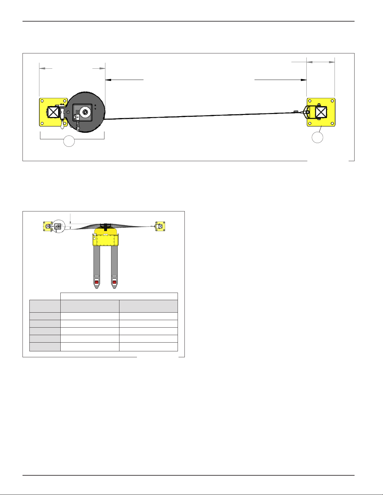
The SpanGuard Mesh Safety Barrier requires a minimum
concrete thickness of 4in [102mm] to provide proper unit
support.
10.00in
254mm
23.42in
595mm
CLEAR OPENING WIDTH
B
A
1.
Titan HD Concrete Anchor Installation Instructions
Tools Required:
Hammer Drill with ¾” x 8” Concrete Drill Bit
Impact Wrench with 1‑1/8” Impact Socket
Installation:
Drill a ¾” Diameter hole in the concrete. The hole should be drilled a minimum of 8” deep
or completely through the concrete.
Using a drill bit that is too small or excessively worn will make it very hard to install the
anchor. Using a drill bit that is too large will reduce the anchors load capacity.
Use compressed air to blow the concrete dust out of the hole. If this is not done, you may
not be able to tighten the anchor completely.
Using the Impact wrench and 1‑1/8” socket, install the anchor through the base plate and
into the hole you drilled into the concrete.
Securely tighten all anchors with the impact wrench. Make sure the hex washer head is in
contact with the base plate.
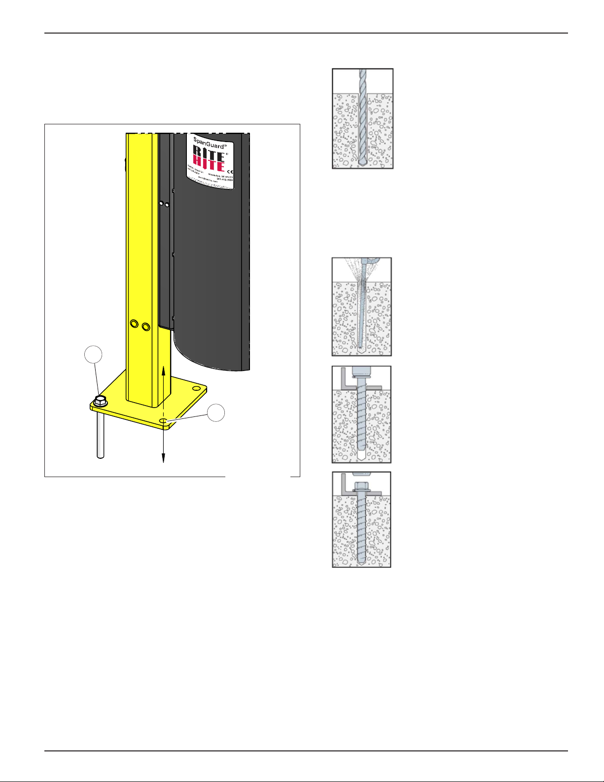
Position the safety barrier in its
intended position. Use the base plate
of the post (B) as a template and
drill the appropriate size hole in the
concrete per anchor being used. The
hole should be drilled a minimum of
1in [25mm] deeper than the length of
the anchor or completely through the
concrete.
Using a drill bit that is too:
– small or excessively worn will
make it very hard to install the
anchor.
– large will reduce the anchor load
capacity.
2.
Titan HD Concrete Anchor Installation Instructions
Tools Required:
Hammer Drill with ¾” x 8” Concrete Drill Bit
Impact Wrench with 1‑1/8” Impact Socket
Installation:
Drill a ¾” Diameter hole in the concrete. The hole should be drilled a minimum of 8” deep
or completely through the concrete.
Using a drill bit that is too small or excessively worn will make it very hard to install the
anchor. Using a drill bit that is too large will reduce the anchors load capacity.
Use compressed air to blow the concrete dust out of the hole. If this is not done, you may
not be able to tighten the anchor completely.
Using the Impact wrench and 1‑1/8” socket, install the anchor through the base plate and
into the hole you drilled into the concrete.
Securely tighten all anchors with the impact wrench. Make sure the hex washer head is in
contact with the base plate.
Use compressed air to clean the
drilled hole so you can tighten the
anchor completely.
3.
Titan HD Concrete Anchor Installation Instructions
Tools Required:
Hammer Drill with ¾” x 8” Concrete Drill Bit
Impact Wrench with 1‑1/8” Impact Socket
Installation:
Drill a ¾” Diameter hole in the concrete. The hole should be drilled a minimum of 8” deep
or completely through the concrete.
Using a drill bit that is too small or excessively worn will make it very hard to install the
anchor. Using a drill bit that is too large will reduce the anchors load capacity.
Use compressed air to blow the concrete dust out of the hole. If this is not done, you may
not be able to tighten the anchor completely.
Using the Impact wrench and 1‑1/8” socket, install the anchor through the base plate and
into the hole you drilled into the concrete.
Securely tighten all anchors with the impact wrench. Make sure the hex washer head is in
contact with the base plate.
Use an impact wrench and 3/4in
socket to install the (provided)
3/4in x 7in Titan HD®concrete
anchors (A) through base plate
and into the holes drilled into the
concrete.
4.
Titan HD Concrete Anchor Installation Instructions
Tools Required:
Hammer Drill with ¾” x 8” Concrete Drill Bit
Impact Wrench with 1‑1/8” Impact Socket
Installation:
Drill a ¾” Diameter hole in the concrete. The hole should be drilled a minimum of 8” deep
or completely through the concrete.
Using a drill bit that is too small or excessively worn will make it very hard to install the
anchor. Using a drill bit that is too large will reduce the anchors load capacity.
Use compressed air to blow the concrete dust out of the hole. If this is not done, you may
not be able to tighten the anchor completely.
Using the Impact wrench and 1‑1/8” socket, install the anchor through the base plate and
into the hole you drilled into the concrete.
Securely tighten all anchors with the impact wrench. Make sure the hex washer head is in
contact with the base plate.
Securely tighten all anchors to
65ft‑lbs [88Nm] with the impact
wrench. Make sure the hex washer
head is in contact with the base plate.
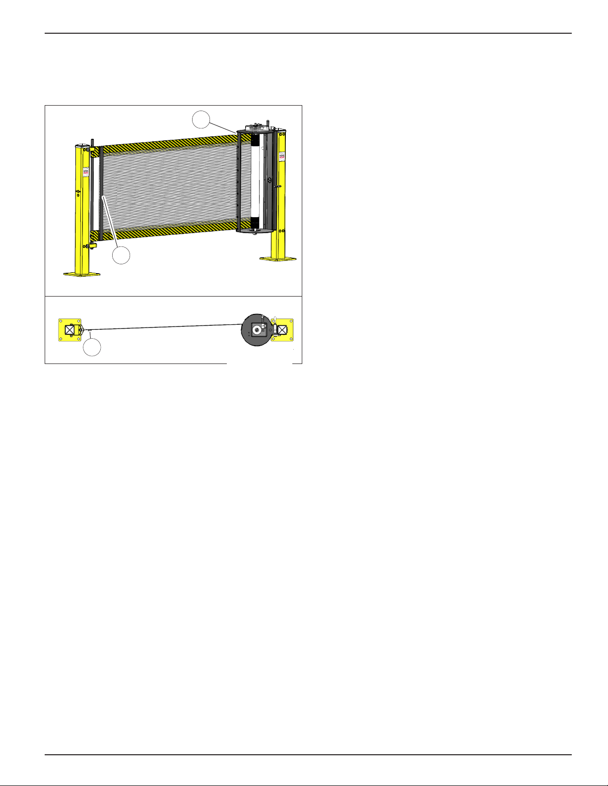
5. Repeat this process for all of the concrete anchors on
the post.
*Image credits: Titen HD Concrete Anchor instructions
(strongtie.com)
Figure 4
Rite‑Hite®Installation/Service/Owner's Manual SpanGuard®Mesh Safety Barrier
Publication: AMEN00136 2019-11-22 5

OPERATION
Extending Barrier
CRANK TO WORM SHAFT
BUSHING BLOCK KEY
CRANK
ENGAGING HANDLE
2
1
A
B C D
E. Curtain Tube Handle
F. Latch Post Assembly
G1. Bottom Hasp
G2. Top Hasp
CRANK TO WORM SHAFT
BUSHING BLOCK KEY
CRANK
ENGAGING HANDLE
2
1
G1
G2
E
F
1. At the basket post assembly:
• Remove the crank (D) from the crank storage clip (A).
• Place the crank on worm shaft (C) to disengage
worm from worm gear by back threading until free.
• Lock worm shaft (C) in place by pushing it toward
the unit, the bushing block locking key (B) will
engage and hold it in place.
2. Grasp the curtain tube handle (E) and pull curtain
from storage basket by walking across the opening
to latch post assembly (F).
3. To latch the curtain tube handle to the latch post,
place the lower end of the curtain handle in the bottom
hasp (G1) and rotate the top hasp (G2) up and over
the top end of the curtain tube handle. Ensure curtain
tube handle is fully engaged in latch post.
4. Return to the basket post and engage the worm
to the worm gear by releasing the locking key (B).
5. Re‑thread the worm to the worm shaft (C)
to begin tensioning the curtain.
6. Tighten curtain to desired tension.
Figure 5
Figure 6
SpanGuard®Mesh Safety Barrier Installation/Service/Owner's Manual Rite‑Hite®
6 Publication: AMEN00136 2019-11-22

OPERATION
Storing Barrier
1. At the basket post assembly (Figure 5):
• Remove the crank (D) from the crank storage clip (A).
• Place the crank on the worm shaft (C) and turn the
crank (D) to release all curtain tension. Disengage
worm from worm gear by back threading until free.
• Lock worm shaft in place by pushing it toward the unit,
the locking key (B) will engage and hold it in place.
BUMPER STOPS
AGAINST POST
QUICK
RELEASE
PIN
(5) SCREWS FOR ROLLER ACCESS
BASKET ROTATION
H
BUMPER STOPS
AGAINST POST
QUICK
RELEASE
PIN
(5) SCREWS FOR ROLLER ACCESS
BASKET ROTATION
I
J
2. Rotate the entire basket assembly 90 degrees
by releasing the quick release pin (H). The quick
release pin will re‑engage and lock the basket in the
horizontal position (I). The bumper (J) stops against
the post.
3. At the latch post assembly remove the curtain tube
handle from the upper hasp and lower hasp
(Figure 6).
4. Place curtain on floor and remove any twists or folds
that could impede returning the curtain to the storage
basket.
5. At the basket post assembly, place crank (D) on
worm shaft (C) (Figure 5), and roll the curtain into the
basket.
6. With the curtain completely stored inside the basket,
rotate the basket assembly back to the vertical
position by releasing the quick release pin. The quick
release pin will re‑engage and lock the basket in the
vertical position. Return the crank to the storage clip.
Changing Position
BUMPER STOPS
AGAINST POST
QUICK
RELEASE
PIN
(5) SCREWS FOR ROLLER ACCESS
BASKET ROTATION
A
B C
A
Left hand operation position Right hand operation position
All SpanGuards are assembled in a left hand operation
position. To determine position:
– Stand facing the mounting post with the curtain storage
basket between the post and yourself.
– The worm shaft and bushing block assembly should be
on the left hand side of the unit.
To convert the operation position to a right hand
conguration:
– Remove the (2) 3/8in bolts (A) from the bushing block
worm shaft assembly.
– Remove 2 hole plugs (B) from top of storage basket.
– Reattach bushing block worm shaft assembly in
opposite mounting holes using (2) 3/8in bolts (A) and
insert hole plugs (B) in vacant holes (C).
MAINTENANCE
Clean the unit as needed.
NOTE: In exterior installations, the curtain may need to be
replaced at shorter intervals as additional weathering may
occur.
Monthly:
1. Operate the unit and inspect for damage
(e.g. tears in the curtain, steel that is bent).
2. Replace curtain if sewing becomes frayed or there is
significant damage to the mesh or strapping.
3. Check that all fasteners are secure.
4. Ensure mounting anchors to be firmly tightened.
5. Lubricate gears, roller tube, and bushings as needed
for smooth rolling and unrolling of curtain. Use
Lubriplate® No. 630‑AA or equivalent.
Figure 7
Figure 8
Rite‑Hite®Installation/Service/Owner's Manual SpanGuard®Mesh Safety Barrier
Publication: AMEN00136 2019-11-22 7

MAINTENANCE
Curtain Replacement
Removal
1. At the basket post assembly (Figure 5):
• Remove the crank (D) from the crank storage clip (A).
• Place the crank on worm shaft (C) to disengage
worm from worm gear by back threading until free.
• Lock worm shaft (C) in place by pushing it toward
the unit, the locking key (B) will engage and hold it
in place.
2. Rotate the entire basket assembly 90 degrees by
releasing the locking key (H). The locking key will
re‑engage and lock the basket in the horizontal
position (I). The bumper (J) stops against the post
(Figure 7).
3. At the latch post assembly remove the curtain tube
handle from the upper hasp and lower hasp (Figure 6).
4. Place curtain on floor and remove any twists or folds
that could impede returning the curtain to the storage
basket.
5. At the basket post assembly, place crank (D) on
worm shaft (C) (Figure 5), and roll the curtain into the
basket.
6. With the curtain completely stored inside the basket,
rotate the basket assembly back to the vertical
position by releasing the locking key. The locking
key will re‑engage and lock the basket in the vertical
position. Return the crank to the storage clip.
BUMPER STOPS
AGAINST POST
QUICK
RELEASE
PIN
(5) SCREWS FOR ROLLER ACCESS
BASKET ROTATION
A
7. To access curtain, remove the (5) 1/4‑20 self
threading screws (A) (Figure 9) from upward
facing basket and remove shroud.
NOTE:Do not remove the rivets.
B
8. Unwind curtain from roller tube. After the curtain
is completely unwound from roller tube, remove
the 2 fasteners (B) that attach the curtain to the
tube. Detach touch and hold fastener and remove
remaining curtain end.
Figure 9
Figure 10
SpanGuard®Mesh Safety Barrier Installation/Service/Owner's Manual Rite‑Hite®
8 Publication: AMEN00136 2019-11-22

MAINTENANCE
Curtain Replacement continued
Installation
PROTECTED
AREA ON THIS
SIDE
STIFFENER, THIS SIDE
CURTAIN ATTACHED TO THE SIDE OF TUBE NEAREST SLOT
(BASKET COVERS
REMOVED FOR
CLARITY)
A
B
PROTECTED
AREA ON THIS
SIDE
STIFFENER, THIS SIDE
CURTAIN ATTACHED TO THE SIDE OF TUBE NEAREST SLOT
(BASKET COVERS
REMOVED FOR
CLARITY)
PROTECTED
AREA ON THIS
SIDE
STIFFENER, THIS SIDE
CURTAIN ATTACHED TO THE SIDE OF TUBE NEAREST SLOT
(BASKET COVERS
REMOVED FOR
CLARITY)
PROTECTED
AREA ON THIS
SIDE
STIFFENER, THIS SIDE
CURTAIN ATTACHED TO THE SIDE OF TUBE NEAREST SLOT
(BASKET COVERS
REMOVED FOR
CLARITY)
Basket shroud removed for clarity.
Top View
10.00in
254mm
23.42in
595mm
CLEAR OPENING WIDTH
Protected Area
B
1. Position curtain on floor in front of basket so curtain
stiffeners (B) are closest to the primary area being
protected. The curtain is always attached to the side
of the roller tube nearest the basket entry slot (A).
2. Center curtain on tube and attach by applying
pressure to touch and hold fastener. Insert a tek
screw into each curtain strap and the roller tube.
Once the curtain is attached, place the crank on roller
tube shaft and roll the curtain on to tube.
3. After curtain is wound on tube, reinsert the (5) 1/4‑20,
self threading cover mounting screws (A) (Figure 9).
4. Rotate the basket back to a vertical position
(Figure 7), reengage the worm to the worm gear and
return the crank to the crank storage clip (Figure 5).
Figure 11
Rite‑Hite®Installation/Service/Owner's Manual SpanGuard®Mesh Safety Barrier
Publication: AMEN00136 2019-11-22 9

PARTS
SpanGuard – Complete Unit
<1204A003.PDF>
#DESCRIPTION PART #
1 30' Complete Unit 70500001
1 60' Complete Unit 70500002
230' Curtain & Storage Cylinder w/post 19750009
260' Curtain & Storage Cylinder w/post 19750010
330' Curtain & Storage Cylinder w/post & latches 19750011
360' Curtain & Storage Cylinder w/post & latches 19750012
4 48" High Square Post Kit 65650018
5 Single Latching Post 65650017
6 Double Latching Post 65650019
SpanGuard®Mesh Safety Barrier Installation/Service/Owner's Manual Rite‑Hite®
10 Publication: AMEN00136 2019-11-22

PARTS
Basket
#QTY DESCRIPTION PART #
– – BASKET, ASSY, SPANGUARD 12440002
1 1 BASKET,WLDMNT,SPANGUARD –
2 1 SHROUD,BASKET,LARGE,SPNGRD –
3 1 SHROUD,BASKET,SMALL,SPNGRD –
4 20 RVT,POP,LF,BLK,3/16X3/8 –
5 10 SCR,HWH,DR/TP,1/4‑20X1/2 –
6 2 LABEL,BARRIER,HOUSING,SPNGRD –
7 1 BRG,ASSY,BOTTOM,SPANGUARD –
7.1 2 NUT,HEX,NYL LOCK,5/16‑18,ZNC –
7.2 1 PLATE,BEARING,BOTTOM,SPANGUARD –
7.3 2 FLANGE,BRG MNT,52MM –
7.4 1 BRG,BALL,1ID X2OD –
7.5 2 BLT,CARG,5/16‑18X1,Z5 –
8 5 NUT,HEX,NYL LOCK,5/16‑18,ZNC –
92FLANGE,BRG MNT,52MM –
10 1 BRG,BALL,1ID X2OD –
11 5BLT,CARG,5/16‑18X1,Z5 –
12 2 PLUG,NYLON,BLK,5/16 –
13 1 HNDL,PHENOLIC,FIXED,3/8‑16X1/2 –
14 1 SCR,RHMS,PHLP,#10‑24X3/4,ZNC –
15 1 CLIP,GRIP,SPRING,1",ZNC –
16 2 PAD,WEAR,HOUSING,SPANGUARD –
17 1 PIN,ANTI‑ROT,BASKET,SPNGRD –
18 2 NUT,HEX,NYLCK,1/4‑20,Z5 –
19 2SCR,HHMS,1/4‑20X5,GR5,ZNC –
20 1 CAP,VINYL,3/8X1,BLACK –
<1204A003.pdf:3>
Rite‑Hite®Installation/Service/Owner's Manual SpanGuard®Mesh Safety Barrier
Publication: AMEN00136 2019-11-22 11

PARTS
Cylinder, Curtain
2
4
3
1
5
#QTY DESCRIPTION PART #
– – CYLINDER,LOADED,30'SPNGRD 19750015
– – CYLINDER,LOADED,60'SPNGRD 19750016
1 1 CURTAIN,ASSY,XX',SPANGUARD –
2 1 CRANK,ASSY,SPANGUARD 19600001
3 1 ROLLER,ASSEMBLY,SPANGUARD 67202001
4 1 KIT,DRIVE,ROLLER,SPANGUARD 53760098
5 1 BASKET,ASSY,SPANGUARD 12440002
SpanGuard®Mesh Safety Barrier Installation/Service/Owner's Manual Rite‑Hite®
12 Publication: AMEN00136 2019-11-22

PARTS
Post
#DESCRIPTION PART #
1POST,WLDMNT,48" –
2YOKE,MACHINED,CATCH,SPANGUARD –
3YOKE,WLDMNT,CATCH,SPANGUARD –
4CAP,4"X4",STEEL –
5SCR,HWH,DR/TP,1/4‑20X1/2 –
6LABEL,BARRIER,POST,SPNGRD –
7PLUG,NYLON,BLK,1/4 –
8NUT,HEX,NYL LOCK,1/2‑13,ZNC –
9 WSHR,FLAT,1/2X1‑3/8X7/64,ZNC –
10 SCR,HHMS,1/2‑13X5.5,Z5 –
11 PLUG,PLSTC,YLW,9/16 –
12 ANCHOR,CONCRETE,HH,3/4X7,ZINC –
15 PIN,ASSY,QUICK RELEASE 64040031
<1204A003.pdf:2>
Rite‑Hite®Installation/Service/Owner's Manual SpanGuard®Mesh Safety Barrier
Publication: AMEN00136 2019-11-22 13

PARTS
Roller Tube and Curtain
1
2
3 5
6
4
7
<1204A003.PDF:5>
#QTY DESCRIPTION PART #
– – ROLLER, ASSEMBLY, SPANGUARD 67202001
1 – ROLLER TUBE, WLDMNT, SPANGUARD –
2 – Touch and Hold Fastener,
PSA, HOOK, BLK, 2IN
–
– – CURTAIN,ASSY,30',SPANGUARD 28200052
– – CURTAIN,ASSY,60',SPANGUARD 28200053
3 1 CURTAIN,SEWN,SPANGUARD XX' –
4 1 HNDL,PULL,CURT,SPANGUARD –
5 2 PLUG,PLSTC,BLK,7/8,RBD –
6 2 RVT,POP,LF,BLK,3/16X3/8 –
7 2 SCR,HWH,DR/TP,1/4‑14X1‑1/4 –
SpanGuard®Mesh Safety Barrier Installation/Service/Owner's Manual Rite‑Hite®
14 Publication: AMEN00136 2019-11-22

PARTS
Drive
<1204A003.PDF:6>
#QTY DESCRIPTION PART #
– – KIT, DRIVE, ROLLER, SPANGUARD 53760098
1 1 GEAR,WORM,SPROCKET –
2 2 RING,RTNG,EXT,1.0SHAFTX.042 –
3 1 KEY,1/4SQ x 1,ZINC –
4 1 SHAFT,WORM DRIVE,ZINC –
5 1 COLLAR,SHAFT,LOCK,.75ID,ZNC –
6 1 SPRING,COMP,.968ODX2.25L –
7 1 SPRING,COMP,.468O.D.X.78L,ZNC –
8 1 BSHG ASSY,CRANK,SLOTTED –
92WSHR,LOCK,SPLIT,3/8,ZNC –
10 2 SCR,HHMS,3/8‑16X2‑1/2,Z5 –
11 1KEY,LOCKING,SPANGUARD –
12 1 SHROUD,GEAR,SPANGUARD –
Crank
<1204A003.PDF:6>
#QTY DESCRIPTION PART #
– – CRANK, ASSY, SPANGUARD 19600001
13 1 HNDL,STEEL,SWIVEL,3/8‑16X4,ZNC –
14 1 LEVER,WLDMNT,CRANK,SPANGUARD –
15 1 NUT,HEX,NYLCK,3/8‑16,Z5 –
16 1 SCR,RHMS,PHLP,#10‑24X3/4,ZNC –
17 1 NUT,HEX,NYL LOCK,#10‑24,ZNC –
18 2 WSHR,FLAT,1/4X3/4X1/16,ZNC –
19 1MAG,RND,14LB,1‑3/8OD,3/16HOLE –
Rite‑Hite®Installation/Service/Owner's Manual SpanGuard®Mesh Safety Barrier
Publication: AMEN00136 2019-11-22 15

16 www.ritehite.com Publication: AMEN00136 2019-11-22
LIMITED PRODUCT WARRANTY SpanGuard®Mesh Safety Barrier
Rite‑Hite Company, LLC and its affiliates (collectively "Rite‑Hite") warrant that the Product sold to the Owner will be
free of defects in design, materials and workmanship (ordinary wear and tear excepted) for the periods set forth below
("Limited Warranty").
One (1) Year(s) on all mechanical and electrical parts (non‑prorated).
One (1) Year(s) labor, based on Rite‑Hite approved travel and labor repair times.
REMEDIES
Parts: Rite‑Hite's obligations under this Limited Warranty are limited to repairing or replacing, at Rite‑Hite's option, any
part which is determined by Rite‑Hite to be defective during the applicable warranty period. Such repair or replacement
shall be Rite‑Hite's sole obligation and the Owner's exclusive remedy under this Limited Warranty.
Labor: Rite‑Hite will provide warranty service without charge for labor per the specified warranty period. Thereafter, a
charge will apply to any repair or replacement under this Limited Warranty.
CLAIMS Claims under this Limited Warranty must be made (i) within 30 (thirty) days after discovery and (ii) prior to
expiration of the applicable warranty period. Warranty period commences on the date of shipment. Claims shall be made
in writing or by contacting the representative from whom the Product was purchased directly. Owner must allow Rite‑Hite
or its agent, a reasonable opportunity to inspect any Product claimed to be defective and shall, at Rite‑Hite's option, either
(x) grant Rite‑Hite or its agent access to Owner's premises for the purpose of repairing or replacing the Product or (y)
return of the Product to the Rite‑Hite, F.O.B. Rite‑Hite's factory.
NOT WARRANTED Rite‑Hite does not warrant against and is not responsible for wear items such as fuses, batteries,
bulbs, vision and seals. No implied warranty shall be deemed to cover damages that result directly or indirectly from: (i)
the unauthorized modification or repair of the Product, (ii) damage due to misuse, neglect, accident, failure to provide
necessary maintenance, or normal wear and tear of the Product, (iii) failure to follow Rite‑Hite's instructions for installation,
failure to operate the Product within the Product's rated capacities and/or specified design parameters, or failure to
properly maintain the Product, (iv) use of the Product in a manner that is inconsistent with Rite‑Hite's guidelines or local
building codes, (v) movement, settling, distortion, or collapse of the ground, or of improvements to which the Products are
affixed, (vi) fire, flood, earthquake, elements of nature or acts of God, riots, civil disorder, war, or any other cause beyond
the reasonable control of Rite‑Hite, (vii) improper handling, storage, abuse, or neglect of the Product by Owner or by any
third party.
DISCLAIMERS THIS LIMITED WARRANTY IS EXCLUSIVE AND IN LIEU OF ALL OTHER REPRESENTATIONS
AND WARRANTIES, EXPRESS OR IMPLIED, AND RITE‑HITE EXPRESSLY DISCLAIMS AND EXCLUDES
ANY IMPLIED WARRANTIES OF MERCHANTABILITY OR FITNESS FOR PURPOSE. RITE‑HITE SHALL NOT
BE SUBJECT TO ANY OTHER OBLIGATIONS OR LIABILITIES, WHETHER ARISING OUT OF BREACH OF
CONTRACT, WARRANTY, TORT (INCLUDING NEGLIGENCE AND STRICT LIABILITY) OR OTHER THEORIES
OF LAW, WITH RESPECT TO THE PRODUCTS SOLD OR SERVICES RENDERED BY RITE‑HITE, OR ANY
UNDERTAKINGS, ACTS, OR OMISSIONS RELATING THERETO.
LIMITATION OF LIABILITY IN NO EVENT SHALL RITE‑HITE BE RESPONSIBLE FOR, OR LIABLE TO ANYONE
FOR, SPECIAL, INDIRECT, COLLATERAL, PUNITIVE, INCIDENTAL, OR CONSEQUENTIAL DAMAGES, EVEN IF
RITE‑HITE HAS BEEN ADVISED OF THE POSSIBILITY OF SUCH DAMAGES. Such excluded damages include, but
are not limited to, personal injury, damage to property, loss of goodwill, loss of profits, loss of use, cost of cover with any
substitute product, interruption of business, or other similar indirect financial loss.
170714
GLOBAL SALES AND SERVICE Representatives in All Major Cities
RITE-HITE WORLD HEADQUARTERS
8900 N. Arbon Drive
P.O. Box 245020
Milwaukee, Wisconsin 53224
RITE-HITE CHINA
First Floor, Building #3,
558 Tongxie Road,
Changning District
Shanghai 200335, China
RITE-HITE LATIN AMERICA
Alameda Lorena 800, conj. 1310
‑ Jardim Paulista
São Paulo‑SP, CEP 10424‑001
‑ Brazil
RITE-HITE GMBH
Carl‑Zeiss‑Strasse 3
34471 Volkmarsen, Germany
414-355-2600
U.S. Only: 1-800-456-0600
+86-21-6237-6333 +55-11-3527-9590 +49-5693 98700
Table of contents
Other RITE-HITE Safety Equipment manuals
Popular Safety Equipment manuals by other brands

Petzl
Petzl GRIGRI 2 instructions

Thiele
Thiele TWN 0827/1 Mounting instructions

NOVOLUX
NOVOLUX ES725-VISERA.POLIC. instructions

SKYLOTEC
SKYLOTEC ERGOGRIP SK 12 Instructions for use

Robur
Robur 8091 Operating and maintenance instructions

Spanset
Spanset Ergo Horizontal Safety Line User operating instructions