SET MAKINA TIGER Manual
TIGER DRILL
Maintenance and Instructions Manual

1
WARNING
SET-A Makina
This manual contains important information on safety. Before carrying out any handling or use
operation consult this use and maintenance manual.
This manual contains copyright reserved information. All rights reserved.
Any form of reproduction, adaptation, or translation without the previous written consent of
SET-A Makina is forbidden.
SET-A Makina is not liable for direct or indirect damage to persons or objects due to the use of
this manual or machine in conditions different than those prescribed or which do not guarantee
the operator's safety.
All data contained in this manual are indicative and not binding, given that SET-A Makina
reserves the right to modem or vary its machines without any previous warning.
General Information
Manual content and use
Keep this manual in a dry and safe place for future reference, so that it is not ruined and is always
available for consultation.
This manual cannot replace the user's experience but it does supply all the information for correct
machine use.
If you need copies or up-dates, exclusively contact the SET-A Makina, which will supply indications on
the matter and solve any problems.

2
CONTENTS
CONTENTS................................................................................................................................................................................ 2
PRESENTATION ....................................................................................................................................................................... 3
GENERAL NOTES ON DELIVERY............................................................................................................................................ 4
Guarantee.............................................................................................................................................................................. 4
Parts subject to wear are not covered by the guarantee. ...................................................................................................... 4
Modifications To The Machine............................................................................................................................................... 4
Identification Of Spare Parts.................................................................................................................................................. 4
TECHNICAL DESCRIPTION...................................................................................................................................................... 5
TECHNICAL CHARACTERISTICS ............................................................................................................................................ 6
SAFETY ..................................................................................................................................................................................... 7
General Information Concerning Safety ................................................................................................................................ 7
Safety Prescriptions............................................................................................................................................................... 7
HANDLING AND TRANSPORTATION ...................................................................................................................................... 8
POSITIONING............................................................................................................................................................................ 9
Positioning for vertical work (Anchoring down jack) .............................................................................................................. 9
Column positioning ................................................................................................................................................................ 9
Positioning for horizontal drilling.......................................................................................................................................... 10
VERIFICATIONS AND ADJUSTMENT .................................................................................................................................... 13
USING THE MACHINE ............................................................................................................................................................ 14
Fitting the down the hole hammer (DTH) ............................................................................................................................ 14
Using the machine............................................................................................................................................................... 14
EXTENSION ROD JOINTING.................................................................................................................................................. 15
At the end of the drilling limit: .............................................................................................................................................. 15
ROD AND HAMMER RECOVERING....................................................................................................................................... 16
MACHINE STOPPING AND REMOVAL .................................................................................................................................. 17
MAINTENANCE ....................................................................................................................................................................... 18
Adding Oil............................................................................................................................................................................ 18
Periodical Controls .............................................................................................................................................................. 18
HAMMER BIT SHARPENING .................................................................................................................................................. 19
Reconstructing the tooth support......................................................................................................................................... 20
AIR RECIEVER (OPTIONAL)................................................................................................................................................... 21
TECHNICAL DATA.............................................................................................................................................................. 21
PROBLEM SOLUTION SUGGESTIONS ................................................................................................................................. 22
APPENDIX I ............................................................................................................................................................................. 23
APPENDIX II ............................................................................................................................................................................ 24
APPENDIX III ........................................................................................................................................................................... 25

3
PRESENTATION
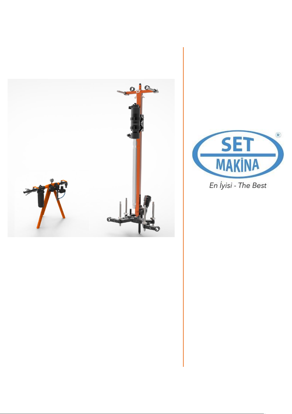
‘TIGER DRILL’ is an pneumatic drill ideal for making large diameter holes (95 mm – 3.7 inch). It is
mainly used for making holes for the passage of diamond wire.
Practicality in use, derived from its simple construction, and the lightness of the structure are its main
characteristics.
‘TIGER DRILL’ is equipped with a pneumatic rotation head which combined with the down the hole
hammer permits drilling linearity to be maintained, reaching considerable depths at high penetration
speeds.
Other construction characteristics permit the drill height from the ground to be kept to a minimum, in the
case of horizontal drills.
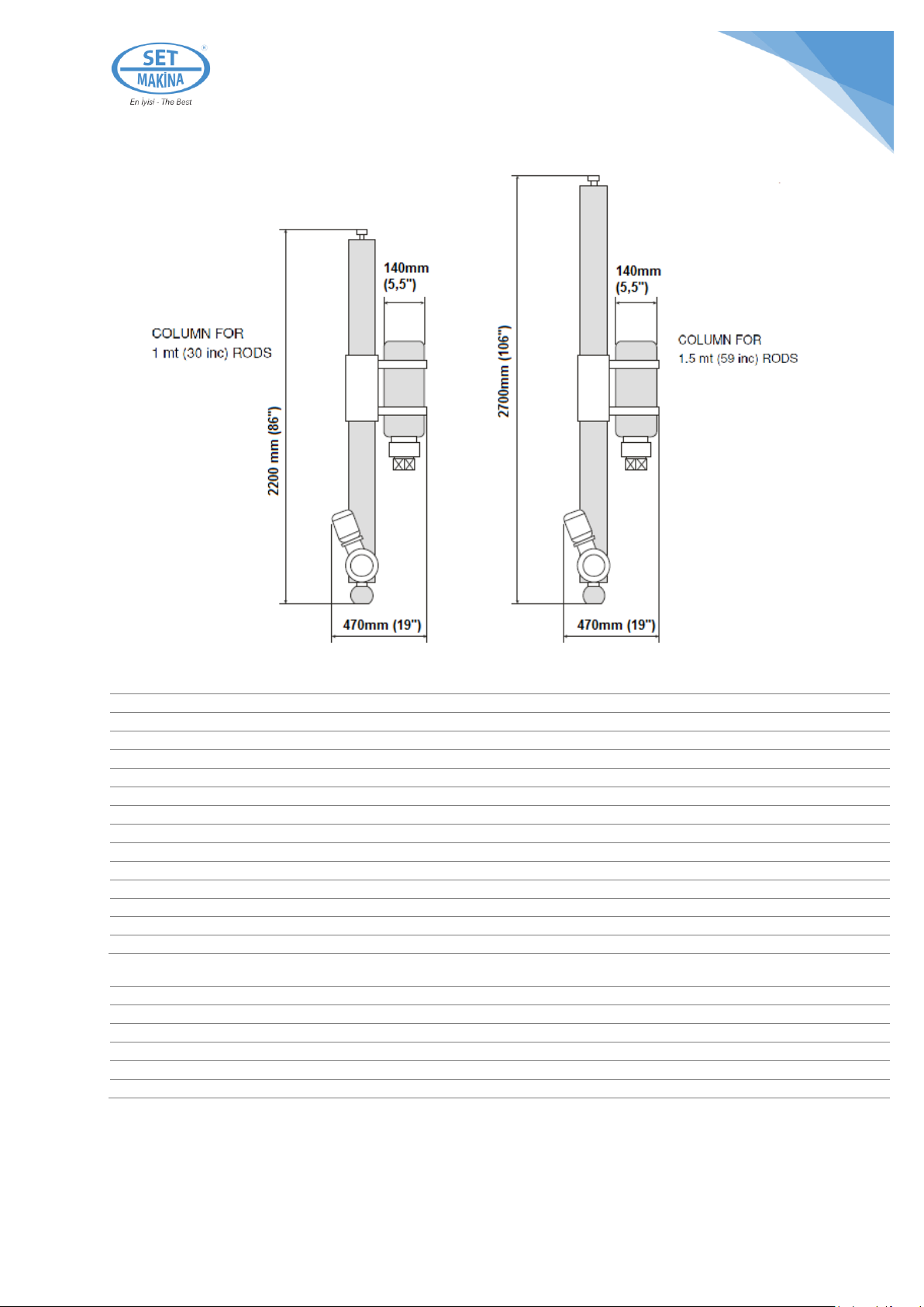
The standard column is sized for the use of 1000 mm. extension rods; on request, extension rods 1500
mm. long can be supplied.

4
GENERAL NOTES ON DELIVERY
On receipt of the machine, open the package and check that:
•The equipment is not damaged.
•In the case of transport damage, inform the forwarder and / or the transport insurance company
In a detailed way, immediately on delivery.
•The supply corresponds to the order specifications
If any pieces are missing, immediately inform the SET-A MAKINA within 8 days of receipt.
Guarantee
The machine is supplied and guaranteed to be free from fabrication faults or defective material for a
period of 1 year from the date on the transport document.
This guarantee, concerning faults and defects due to material, manufacturing and processing, is valid on
condition of reporting them within 8 days time after the relative identification.
Parts proved to be defective will be reaired or replaced, at the discretion of the SET-A MAKINA, on
condition that the said defect does not depend on failure to observe the use and maintenance
instructions, bad or unsuitable use of the equipment or on normal wear.
The parts to be replaced or repaired will be made available ex-our workshop.
The user shall sustain the shipment and transport costs, plus those for the labour, travel and board, if
the repair should necessitate the presence of one of our technicians.
Parts subject to wear are not covered by the guarantee.
Modifications To The Machine
SET-A MAKİNA reserves the right to make all necessary modifications to the machines it manufactures
without any prior notice.
Machine identification
The machine is identified by the number indicated on the card.
Identification Of Spare Parts
When requesting spare parts, always indicate the machine's serial number found on the test card and
the no. of the required part taken from the enclosed lists of spares.

5
TECHNICAL DESCRIPTION
MOD. TIGER DRILL SERİ No. TD___________________
Pneumatic drill comprised of a column supporting the rotating head with an attachment for the down the
hole hammer. The rotating head can be supplied with a thread for rods with a cylindrical, male fitting
(RD 50) or a conical, female fitting (API 2” 3/8).
Rotating head advance via a chain driven by a pneumatic gear
motor.
The machine is supplied as standard with:
•Support column (Appendix I page 23).
•Anchoring down jack with spherical joint for column
engagement (Appendix II page 24) and levelling screws 4
(Appendix II).
•Control unit with line lubricator (Appendix III page 25).
•Socket wrench for column spherical joint locking bolts.
•Socket wrench for levelling screws.
•2 wrenchs for unscrewing the rods.
•Drill steel 22x108 Ø40 400 mm L. for anchoring holes.
•Column anchoring chains (3 pcs, 3 m)
The following are available on request:
•1000 mm. drilling rods (39 in.) or 1500 mm. (59 in.)
depending on column length (see page 6).
•Down the hole hammer.
•1 wrench for hammer disengagement.
•Bit for down the hole hammer.
•Sharpener for hole bottom bit.
•Adapter from RD 50 to API 2” 3/8.
•Dust extractor.
•Air Receiver (see page 21).
6
TECHNICAL CHARACTERISTICS
kg
lbs
2200 mm (86”) column
55
122
2700 mm (106”) column
62
137
Control unit weight
33
73
Rotation head weight
36
80
Down jack weight (complete)
21
47
Down the hole hammer weight (DTH)
25
55
Bit weight
5
11
1 m (39”) rod weight
11
25
1.5 m (59”) rod weight
14
31
Total weight - 2200mm column (excluding down the hole hammer, rods and bit)
135
297
Total weight - 2700mm column (excluding down the hole hammer, rods and bit)
142
323
Advance motor air consumption
800 Lt/min at 6 bar (29 cfm at 87 P.S.I.)
Rotating head air consumption
2000 Lt/min at 6 bar (73 cfm at 87 P.S.I.)
3" down the hole hammer air consumption
4000 Lt/min at 6 bar (146 cfm at 87 P.S.I.)
Total compressed air consumption
6800 Lt/min at 6 bar (219 cfm at 87 P.S.I.)
Lubricating oil consumption
1.5 Lt every 8 hours of work

7
SAFETY
General Information Concerning Safety
The design and manufacturing of this machine in conformity with the Machinery Safety Directive
2006/42/AT, 2006/95/AT LVD Directive, 2004/108/AT EMC Directive (specify relevant provisions and
other applicable directives, if any).
In particular, measures designed to prevent risks to operators were adopted during the design and
construction phases.
The complete documentation of the safety measures adopted is contained in the technical dossier
deposited at the offices of the SET-A Makina.
For some risks it was not possible to find solutions at the design level. In these cases, this manual
indicates the safety prescriptions to adopt to operate in the safest way.
WARNING: SET-A Makina recommends complying with the instructions, procedures and
recommendations of this manual, to adopt all precautions suggest by the technique and to
comply with the accident prevention regulations in force.
Safety Prescriptions
•The installation, maintenance, and use of the machine is reserved to specialised staff.
•Before performing any cleaning or maintenance intervention, check that the power supply is
disconnected.
•Do not remove the fixed protections of the machine protecting the mobile elements.
•Do not put your hands in the pairs where there is a danger of being crushed or trapped.
•The operator should stay by the control group in the most distant and protected position.
•When working and performing control operations the operator must always position himself
behind the control group.
•When the machine or its parts are handled it must idle and the power supply must be
disconnected. This must be performed by specialized staff with the appropriate tools.
•If it is necessary to replace machine components, exclusively use original spare parts.
8
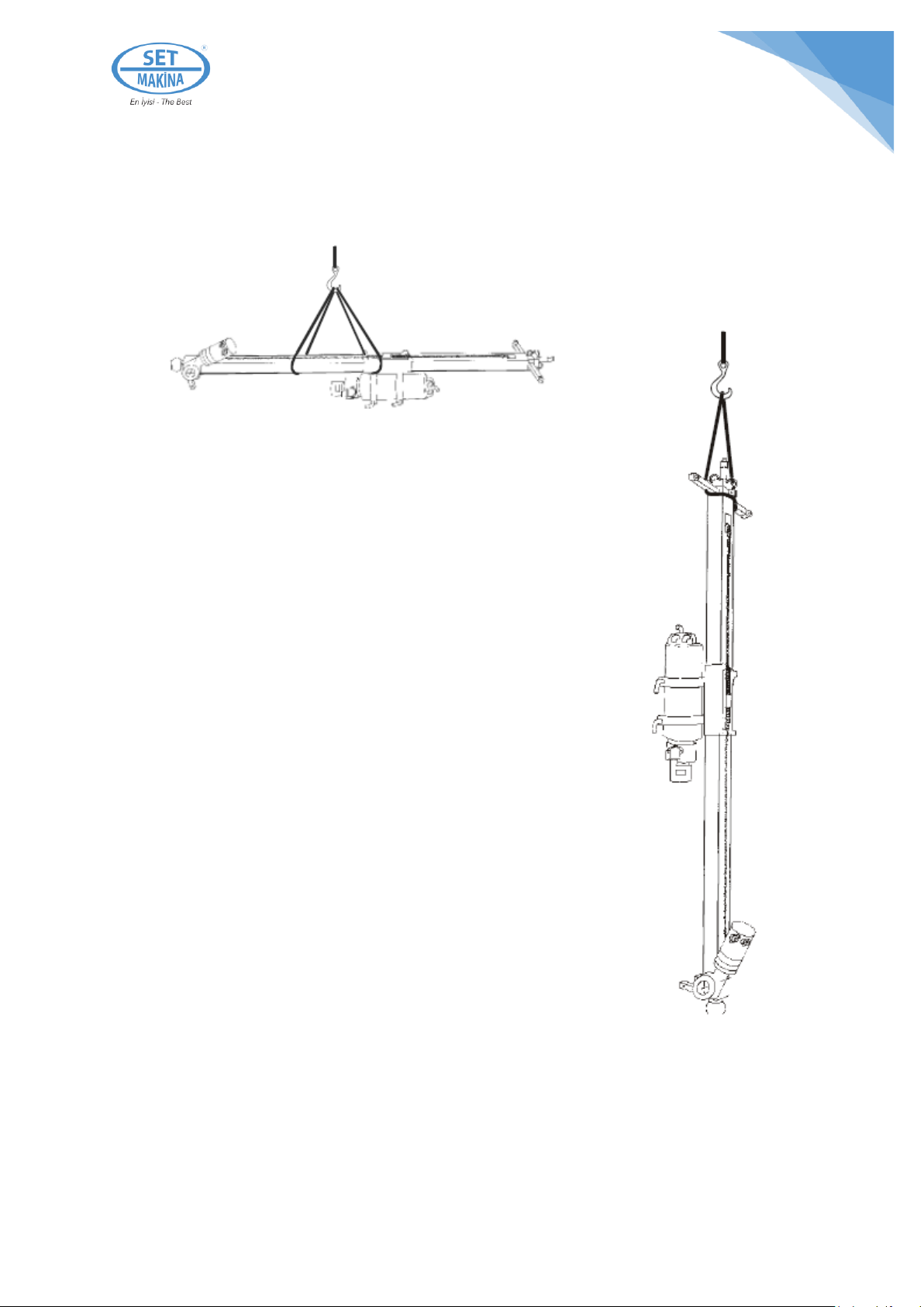
HANDLING AND TRANSPORTATION
WARNING: the handling and transportation of the machine should be carried out by specialised
or adequately trained staff with the support of the adequate lifting equipment.
Slide and rotating head weight 110 kg (245 lb)
Hammer and bit weight 30 kg (66 lb)
Total weight 140 kg (311 lb)

9
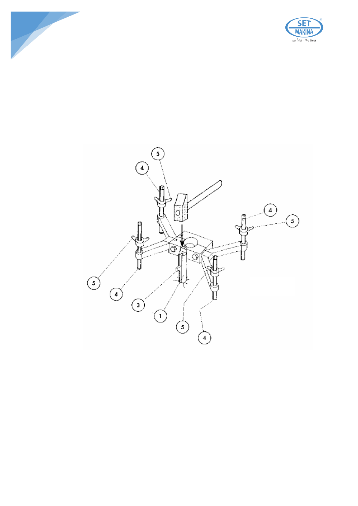
POSITIONING
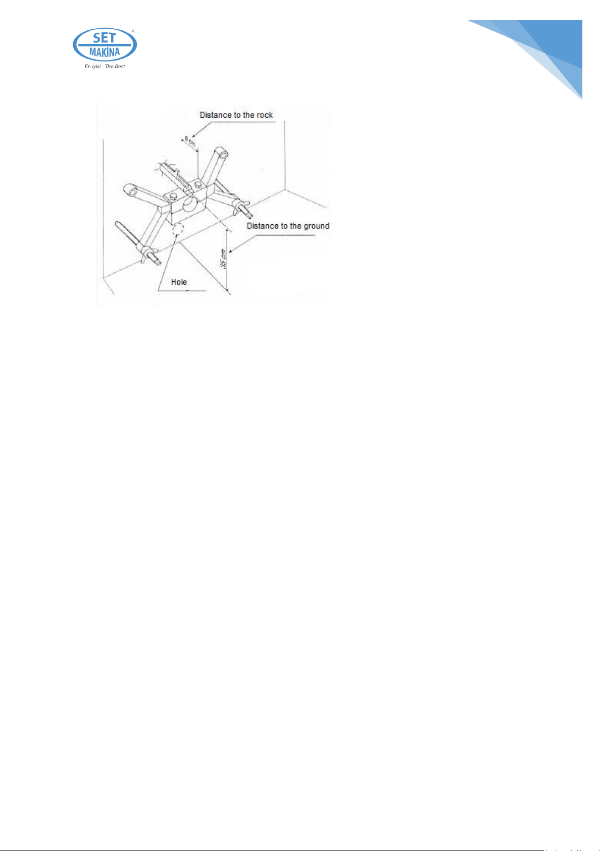
Positioning for vertical work (Anchoring down jack)
1. Using a small drill with a standard drill steel Ø 40 x 400 make a
hole at least 25 cm (10 inc) deep (F) 24 cm (9.5 inc) away from the
point in which you want to drill (Fig. 1a). The hole must be as
perpendicular as possible to the rock face.
2. Insert the grooved pin 1 of the down jack into the hole made
(fig.1b).
WARNING: Never insert the grooved pin 1 as far as to touch the
bottom of the hole otherwise you will experience serious
difficulty in extracting it later.
3. Direct the down jack so that the spherical coupling seat of the
column to the down jack finds itself between the anchoring pin and the
point where the drill will be made (fig. 1b).
4. Position the down jack so that there is a gap of around 8-10 cm
(3-4 inc) (fig. 2) between the rock and the down jack. This space will
facilitate the down jack removal operation.
5. Block the down jack by inserting the conical fixing pin 3 into the
pin grooving 1 (fig.1b). Apply a few hammer blows to the head of the
pin and check that the anchoring is effective (Fig.1b e Fig.2)
6. Stabilise the down jack by forcibly tightening the levelling
screws 4 (fig.2) against the support surface. Block the screws by
tightening the butterfly counter-nuts 5 (Fig.2).
If you have correctly performed these operations, the anchoring of the
column support down jack to the rock has now been performed.
Column positioning
1. Detach the spherical half-shell from the down jack by
unscrewing the tightening bolts 8 (fig.2).
2. Lift the column with cables or a chain, paying attention that the
delicate parts of the machine (joint, motor, …) are not damaged by
accidental impacts.
3. Position the spherical joint 11 (Appendix I) of the column into the halfshell (Appendix II) of the
anchoring down jack.
4. Screw on the previously removed spherical half-shell, taking care that the positioning numbers
9 (Appendix II) of the two half-shells 2 (Appendix II) line up on the same side.
5. Direct the column in the same direction as the hole to make.
Figure 1a
Figure 1b
Figure 2
10
6. Block the column in the spherical seat of the down jack and firmly tighten the locking bolts 8
(Appendix II) with the correct wrench.
7. Manually check the column stability.
If these operations have been performed
correctly, the column is now positioned
and anchored to the rock to be drilld. At
this point, we can free it from the cable or
can we used to lift it with.
Positioning for horizontal drilling
The anchoring of the down jack for
horizontal drilling is similar to that for
vertical drilling.
Keep well in mind that in order to drill as
close as possible to the base of the wall,
the anchoring hole for the down jack must be made at around 35 cm from the height of the ground.
1. After making the anchoring hole, remove the two upper stabilising screws of the
anchoring down jack, (fig. 3) and screw them onto the screw support arms at the top of
the column 13 (Appendix I).
2. Block the down jack as for the vertical position and stabilise it with the two remaining
screws, as in the vertical position.
3. Install the support column following the same procedure as for the vertical positioning,
remembering to check the column stability before freeing it from the sling.
4. Contrast the two screws previously fitted to the column arms against the ground or
another type of support.
Figure 3
11
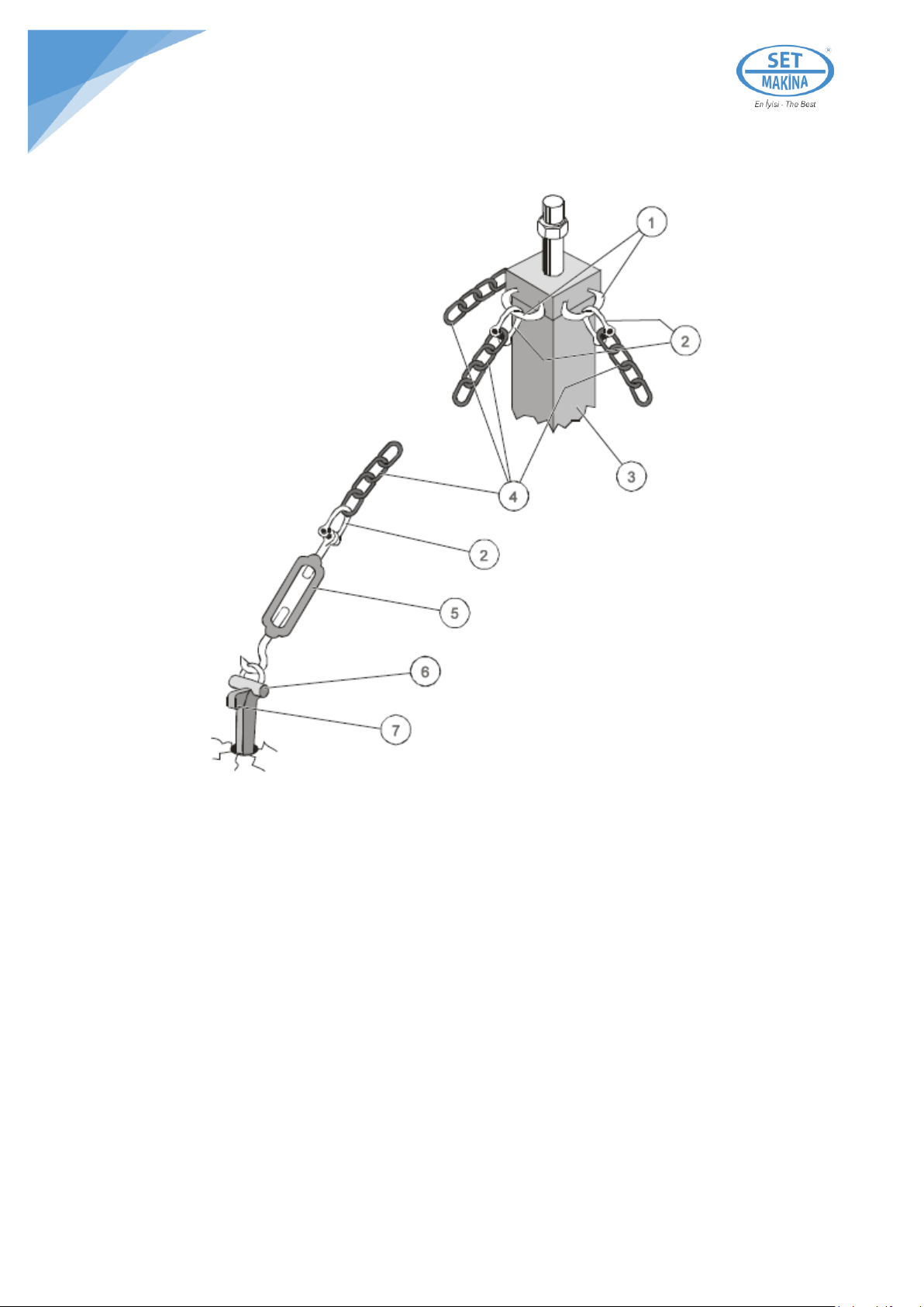
COLUMN ANCHORING WITH CHAINS
1. Make 3 - 34 mm holes 20 cm ( 8 inc) deep
2. Fix the chains (4) to the rings (1) of the column (3) using the hooks (clevises) (2).
3. Slacken the tighteners (5).
4. Fix the chains (4) to the ground using the special anchoring pins (6-7) (see "Down jack
anchoring" procedure).
5. Use the tighteners (5) to tighten the chains equally.
1. Chain fixing rings
2. Hooks (clevises)
3. Column
4. Chains
5. Tightener
6. Pin
7. Plug

12
AIR CONNECTIONS
1. Position the control unit at a suitably safe distance.
2. Direct the control unit to the most suitable and safe
position for performing the operations.
3. Close the compressor 12 (Appendix III) entry valve and
the supply valve for the down the hole hammer 13
(Appendix III) as in fig.4
4. Connect the feeding hose 14 (Appendix III) of the down
the hole hammer to the corresponding fitting on the output
group of the rotating head 6 (Appendix I).
5. Connect the head rotation feeding hoses 15 (Appendix III)
- right and left - to their corresponding fittings 8 (Appendix I)
on the rotating head, paying attention to match the black
marks with the black marks of the rapid fittings.
6. Connect the up and down hoses 16 (Appendix III) to the
corresponding fittings 10 (Appendix I) on the advance motor,
paying attention to match the red marks with the red marks
of the rapid fittings.
7. Position the distribution levers for rotation 1 (Appendix III)
and advance 2 (Appendix III) to closed or rest (central
position) 0 (zero).
Connect the main feeding hose 17 (Appendix III) of the supply
compressor to the corresponding valve 12 (Appendix III) on the
control unit.
For the air supply, use a hose no smaller than 1” 1/4.
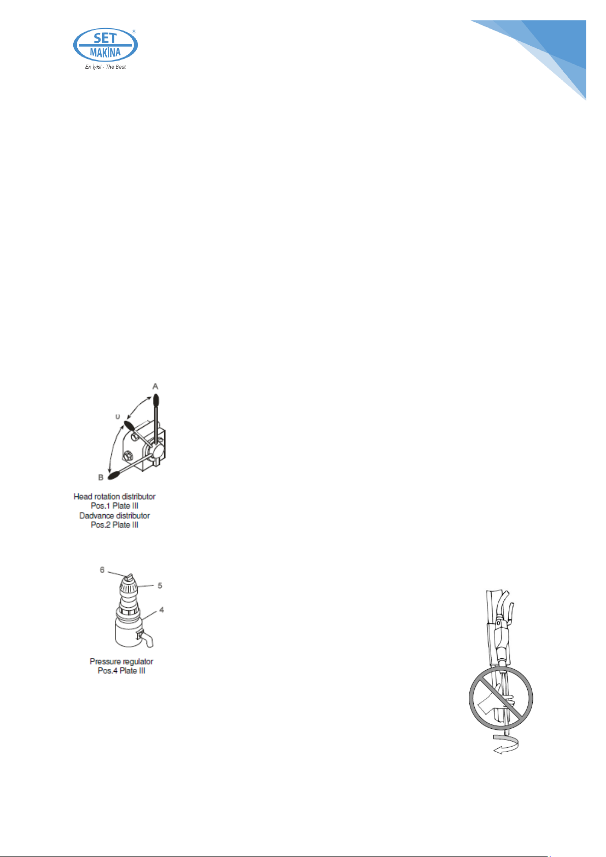
ROTATION
ADVANCE
A –Anticlockwise (rod unscrewing)
A –up (backwards)
0 –Rest
0 –Rest
B –Clockwise (drilling)
B –Down
Figure 4
Figure 5

13
VERIFICATIONS AND ADJUSTMENT
WARNING: if the machine is new or has been idle for a long period, pour some oil directly into
the drill supply pipes for more rapid initial lubrication.
•Check that there is a sufficient amount of lubricating oil in the tank 8 (Appendix III and fig.9) of
the lubricator. If not consult page 18 = maintenance: adding oil.
•Make certain that the compressor supplies enough pressure to position the gauge needle 3
(Appendix III) in the green field of the dial corresponding to 5.5 ÷ 7 bar.
WARNING: this pressure should be kept constantly in the green area during the drill (ideal
pressure 6 bar).
Regulate the passage of the correct amount of oil using the adjustment screw (Appendix III, pos.10).
RECOMMENDED: For proper lubrication, disconnect the feed hose and supply compressed air.
The air should be slightly oily (check with the palm of the hand).
14
USING THE MACHINE
WARNING: before using the machine, check that it is well anchored to the ground and that all
the bolts and air hoses are correctly tightened.
Fitting the down the hole hammer (DTH)
The machine is generally supplied with the down the hole hammer fitted to the rotating head.
The same hammer, has the drilling bit fitted to its bottom end. The type of bit is the one requested by the
customer, or the most suitable one for the material to be drilld.
To fit a down the hole hammer not supplied with the machine, strictly follow the instructions of the
company that supplied the hammer.
The down the hole hammer is screwed on in a clockwise direction to the output group of the rotating
head. Before fitting, make sure that the threaded fitting is the same as the one on the rotating head:
cylindrical RD50 or API Regular 2" 3/8 conical.
The down the hole hammer must be tightened with the special wrenchs supplied (see "Extension rod
joint" page 15).
Using the machine
1. Supply the control unit by opening the valve 12 (Appendix III).
2. Check that the gauge needle 3 (Appendix III) oscillates within the green
field on the dial.
3. Approach the hammer bit to the surface to be drilld. This is performed
by lowering the distribution lever 2 (Appendix III) towards position B of fig.6.
The distributor commands the advance of the rotating head - down the hole
hammer group.
4. Open the valve 13 and rotate and percuss the hammer by lowering
distribution lever 1 (Appendix III) towards position B of fig.6. The hammer bit
rotates clockwise. Release the stopper 6 on the pressure regulation 5 (fig.7)
by unscrewing it anti-clockwise.
5. Regulate the head rotation using the pressure regulator 4 by screwing
and/or unscrewing the knob 5 (fig.7).
6. Drilling has now started.
WARNING: advance only serves to keep the bit close
to the rock to be drilld, and not to keep it pressed
against the rock itself.
Figure 6
Figure 7
15
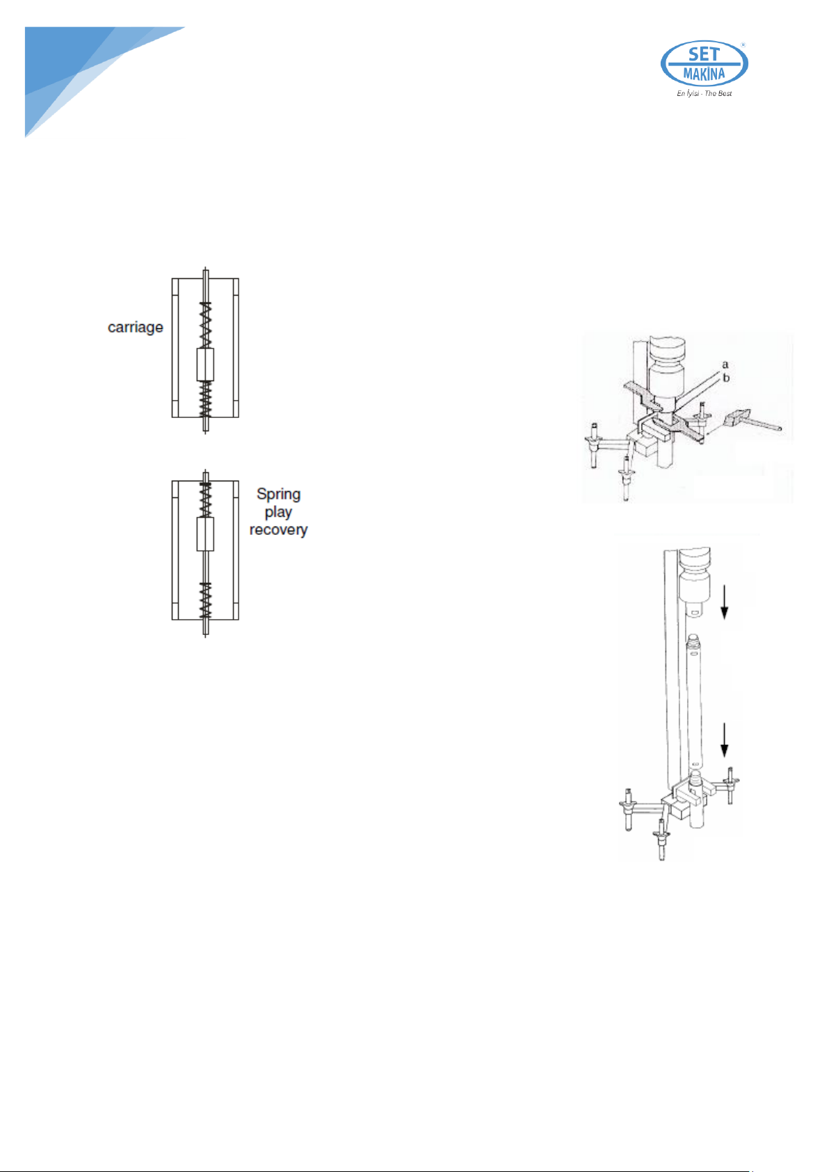
EXTENSION ROD JOINTING
At the end of the drilling limit:
1. Block the advance, rotation and percussion by closing the respective distributors (Appendix III, pos. 1,
pos 2, pos 13).
2. Recover the play of the carriage springs 3 (Appendix I) by slightly lifting up the rotating head (fig.8
and fig.9).
3. Insert the wrench supplied into the seat (a) of the output group
and turn it against the column. This prevents the reducer from
advancing and the rotating head from
becoming damaged by counter-blows
while changing the rods. (fig.10).
4. Insert the wrench supplied into the
seat (b) of the hammer or rod and
keeping the wrench contrasted in (a)
against the column, release the
hammer or rod by applying a few
hammer blows to the wrench in the
seat (b) (fig.10).
5. Remove the wrenchs, rotate the rotating
head in an anticlockwise direction (pos. A of
distributor 1 - fig.5 page 12) and unscrew
the hammer or the rod. Position the rotating
head high on the column, almost as far as it
will go.
6. Manually screw the extension rod onto the hammer or possibly onto the other
rod found in the hole (fig.11).
7. Advance the rotation head and make it rotate clockwise (pos. B of distributor 1 -
fig.5 pag.12) and screw it to the rod or the hammer.
8. After checking that the rod has been screwed both to the head and the hammer
(or possibly to the other rod still found in the drill), start drilling again.
For more joints, repeat the operations described.
WARNING: never unscrew the rods or the hammer with just the force of the rotation head. Keep
the control unit as far away as possible from the column to prevent accidental manouvres.
Figure 8
Figure 9
Figure 10
Figure 11

16
ROD AND HAMMER RECOVERING
1. Block the advance, rotation and percussion by closing the respective distributors and valve 2, 1,
13 Appendix III.
2. Position the rotating head high on the column almost as far as it will go.
3. Insert the wrench supplied into the seat (d) of the rod which finds
itself in the hole and make it rest on the rod guide. In the case of
vertical drilling, this wrench serves to prevent the rods from falling
into the drill at the moment they are unscrewed from the rotating
head.
4. Insert the wrench supplied into the seat (a) on the rotating head
and wedge it against the column.
5. Insert the wrench supplied into the seat (b)
6. Hit the wrench inserted in seat (b) with a hammer and release the
rod, by making it rotate in a clockwise direction.
7. Remove the wrenchs from seats (a) and (b), rotate the head and
unscrew it from the rod.
8. Position the rotating head high up on the column to almost as far
as it will go.
9. Insert the wrench into seat (c), wedge the wrench in seat (d)
against the column; hit the wrench in seat (c) with a hammer to
release the rod and then unscrew it.
10. We have now removed the 1st rod.
11. Approach the rotation head of the 2nd rod which is still found in
the drill.
12. Screw the head to the rod to then make it rise up pulling the
rod with it.
13. By repeating the procedure described, we recover the other
rods and the hammer.
WARNING: never try to unscrew the rods or the hammer with the
force of the rotation head alone. Keep the control unit as far away
from the column as possible with the purpose of avoiding any
accidental manouvres.
Figure 12
Figure 13
17
MACHINE STOPPING AND REMOVAL
After detaching the main supply and discharging the air found in the control unit:
•Detach the feeding hoses from the rotating head, the hammer and advance gear motor;
•Remove the support column from the spherical seat of the anchoring down jack;
•Slacken the butterfly counter-nuts 5 (Fig.14) on the levelling screws 4 and unscrew the screws by 4-
5 cm;
•Apply a few hammer blows to the anchoring pin 1 which by entering the drill, frees the conical plug
3;
•Remove the conical plug and the down jack;
Figure 14
18
MAINTENANCE
Adding Oil
WARNING: before proceeding with the oil addition operations, stop the machine, close the
compressor air supply and discharge any air remaining in the control panel by opening valve 13
Appendix III. This is important because it is dangerous to remove the plug or the lubricator tank
with the control panel under pressure.
To add oil to the line lubricator, with the machine at a standstill and not powered up, unscrew the screw
plug 11 Appendix III and add oil, or directly release the tank by pressing button 19 and by rotating the
lock ring.
If the long idle periods are foreseen, or if the machine is made to operate after being idle for a long time,
pour oil directly into the supply inlets of the rotating head and the advance motor and rotate them slowly
for a few turns to lubricate the mechanical parts well.
Oil to use:
•Mobil ALMO 527
•Petrol Ofisi ROCKDRILL 100
•Shell TORCULA 100
Grease to use:
•Petrol Ofisi SUPERGRES EP00
•Shell GADUS 00
•Mobil LUX EP00
Periodical Controls
Daily: Check the oil level.
Check that all the bolts and the air hoses are suitably tightened
Check the chain tension and adjust it with the tightener 14 (Appendix I) if necessary check the
integrity and wear of the bit.
Weekly: grease the chain pinion 2 (Appendix I) of the advance group using the greasers provided (Part.
A Appendix I). Use the recommended grease or an equivalent one.
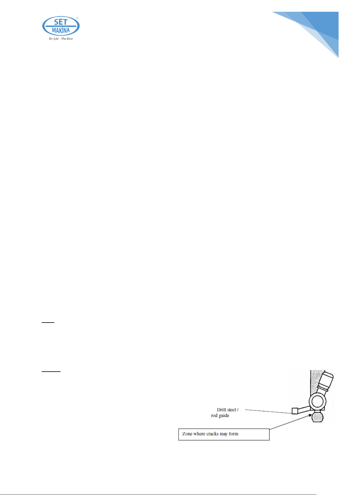
Check that the neck of the sphere is free from cracks. If you notice any cracks, suspend machine use.
19
Figure 15a
Figure 15b
Figure 16a
Figure 16b
Figure 16c
Figure 17a
Figure 17b
Figure 17c
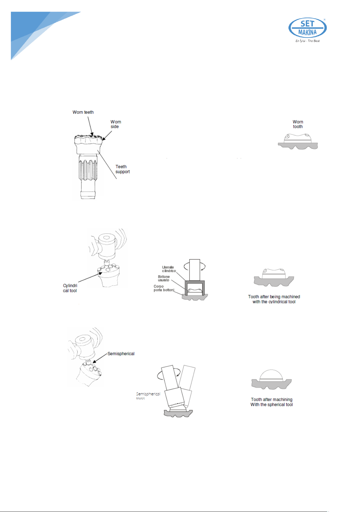
HAMMER BIT SHARPENING
In use, the down the hole hammer bit wears
changing the shape of the teeth (Fig.15a) and
that of the teeth support (Fig.15b).
It is therefore necessary to regenerate both
the tooth shape and that of the teeth support.
Using the special sharpening machine, (optional) with a suitable
cylindrical tool of adequate dimensions, remove the right
amount of material from the teeth support to return the teeth to
a suitable height.
(Figg.16a-b-c).
Change the tool on the sharpener with one with a semi-
spherical profile and reconstruct the tooth's profile in
(Fig.17a-b-c).
Table of contents
Popular Drill manuals by other brands


EINHELL
EINHELL BT-ID 720 E Original operating instructions

Milwaukee
Milwaukee Heavy-Duty 3/8" Hammer-Drills Operator's manual

Narex
Narex EVP 13 H-2C Original operating manual

stayer
stayer PBL120K operating instructions

Black & Decker
Black & Decker CD70KA quick start guide

Hitachi
Hitachi WM 14DBL Handling instructions

Hitachi Koki
Hitachi Koki FDV 16VB2 Handling instructions

EINHELL
EINHELL TE-RH 28 5F Original operating instructions

Black & Decker
Black & Decker GC9600 instruction manual

Clas Ohlson
Clas Ohlson DJC123-120-UK instruction manual

Clipper
Clipper HHD323 owner's manual

Sioux Tools
Sioux Tools 1AM Series instructions