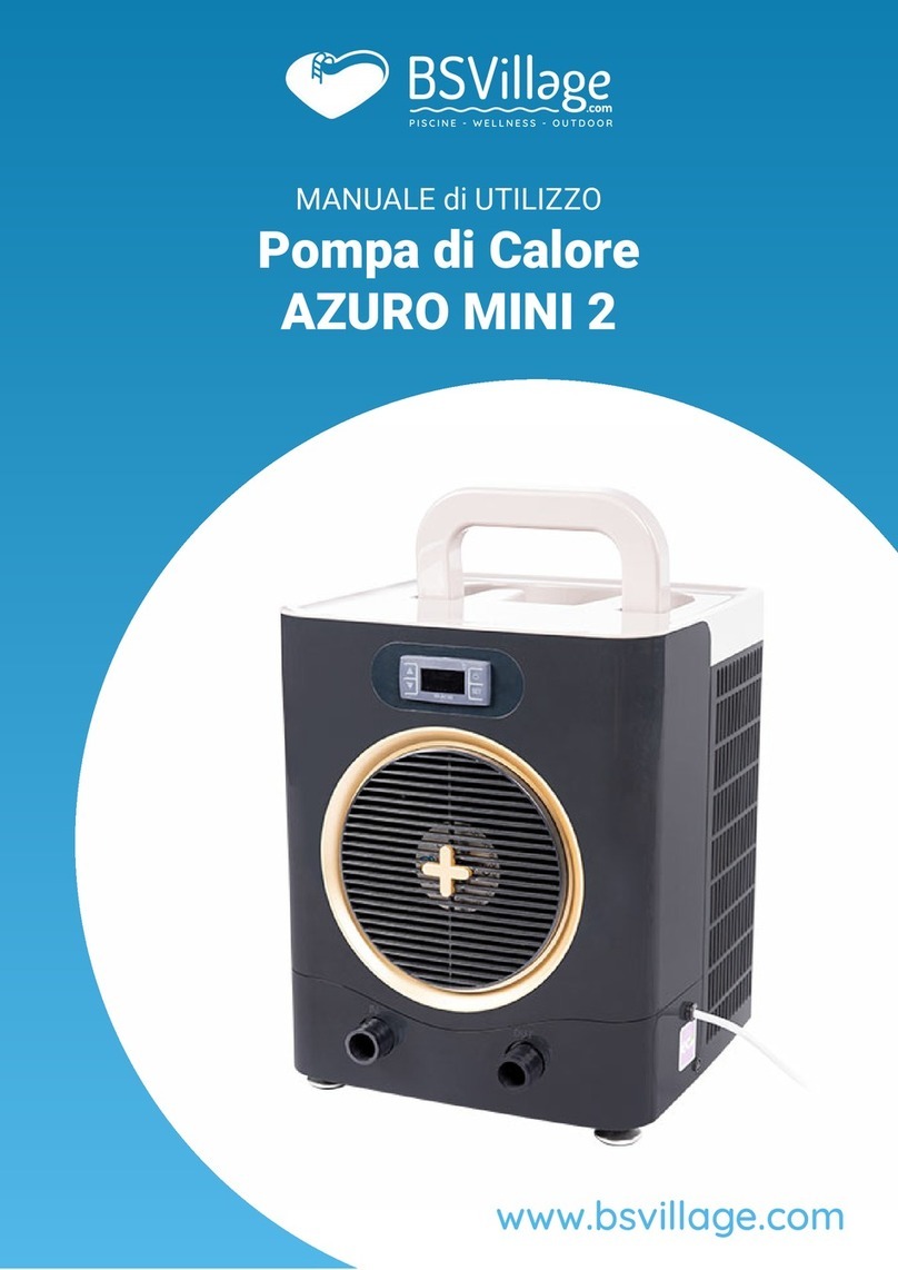
SET Silent 10 User manual

Original Operating Instructions
Open-Air Swimming Pool
Heat Pump Silent 10 / 15 / 20 / 30
SET Energietechnik Ltd.
August-Blessing-Str. 5
D-71282 Hemmingen, Germany
Tel. +49 (0)7150 –9454-0
Fax +49 (0)7150 –2337
www.set-energietechnik.de
info@set-energietechnik.de
Directors:
Frank Fiedler, Dr. Andreas Seibold, Enric Cabré, Carlos Franquesa

2
SET Energietechnik Ltd. * August-Blessing-Str. 5 * D-71282 Hemmingen * Tel.: +49 (0)7150 9454-0 Fax: +49 (0)7150 2337
All rights reserved by SET Energietechnik Ltd., January 2019. Reproduction in whole or in
part, without our permission, is not permitted. Size and design changes in the interests of
technical progress are subject to change without notice.

3
SET Energietechnik Ltd. * August-Blessing-Str. 5 * D-71282 Hemmingen * Tel.: +49 (0)7150 9454-0 Fax: +49 (0)7150 2337
Table of Contents
Page
1 General 4
1.1 Delivery and scope of delivery
1.2 Advice
2 Safety 6
2.1 General safety advice
2.2 Intended use
2.3 Action in an emergency
2.4 Duties of the user
2.5 Residual hazards
3 Technical data 10
3.1 Choice of equipment
3.2 Open-air swimming pool heat pump
3.3 Accessories
3.3.1 External On/Off
3.3.2 Remote control
3.3.3 Pool water heat pump
3.4 Regulation
3.5 Hot gas defrosting
3.6 Range of application / operating limits
4 Transport / installation 13
4.1 Equipment transport
4.1.1 Equipment installation
4.2 Electrical installation
4.2.1 Rotating field monitoring
4.3 Water side connections
4.3.1 Condensate discharge
4.3.2 Pool water connection
5 Commissioning 16
5.1 Commissioning advice
5.2 Regulator displays
5.3 Commissioning
5.4 Condensate discharge test

4
SET Energietechnik Ltd. * August-Blessing-Str. 5 * D-71282 Hemmingen * Tel.: +49 (0)7150 9454-0 Fax: +49 (0)7150 2337
Table of Contents
Page
6 Operation 18
6.1 Setting of the water temperature to be adjusted (target value)
6.2 Changing from heating mode to cooling mode
6.3 Changing from cooling mode to heating mode
6.4 Standby mode
6.5 Sensor calibration
6.6 Hysteresis
6.7 Error messages
7 Maintenance 21
7.1 Advice on maintenance and care
7.2 Complete cleaning
7.3 Condensate discharge
7.4 Fan
7.5 Corrosion protection
7.6 Refrigeration cycle
8 Repairs 23
9 Shutdown 24
9.1 Shutdown advice
9.2 Shutdown
10 Disassembly/disposal 25
11 Appendices 26
Connection diagram - water
Troubleshooting
CE declaration
Leak test protocol (sample)
Safety data sheet - refrigerant R-410A
Circuit diagrams 230 V 1 N
Circuit diagrams 400 V 3 N

5
SET Energietechnik Ltd. * August-Blessing-Str. 5 * D-71282 Hemmingen * Tel.: +49 (0)7150 9454-0 Fax: +49 (0)7150 2337
Dear Customer,
Thank you for deciding on an open-air swimming pool heat pump from SET Energietechnik
Ltd.
You have purchased a powerful open-air swimming pool heat pump which has been
developed according to state-of-the-art technical standards. So that the device will provide
faithful service over a long period of time, we ask you to closely study the operating
instructions, particularly the safety advice.
If you still have any questions about the device after reading the operating instructions,
please do not hesitate to contact us:
E-mail address: info@set-energietechnik.de
If you specify your telephone number, we will call you back free of charge.
We are pleased to receive any feedback from customers and would welcome you getting in
touch with us.
With kind regards,
SET Energietechnik Ltd.
Dr. Andreas Seibold
Managing Director

6
SET Energietechnik Ltd. * August-Blessing-Str. 5 * D-71282 Hemmingen * Tel.: +49 (0)7150 9454-0 Fax: +49 (0)7150 2337
1. General
1.1 Delivery and scope of delivery
Please check your SET open-air swimming pool heat pump for transport damage
immediately upon receipt! Report any cases of damage to the carrier immediately upon
delivery and indicate this on the dispatch document.
If, after unpacking the device, you should discover any transport damage, please contact
your seller or specialist dealer immediately.
Each shipment is accompanied by a delivery note, from which you can see the scope of the
shipment. Please check the completeness of the shipment and report any shortages
immediately to your seller or specialist dealer.
1.2 Advice
These operating instructions should help the user to operate the open-air swimming pool
heat pump properly.
Please read them carefully before using for the first time, so that perfect functioning of this
device can be guaranteed.
Special advice on potential hazards is highlighted in grey.

7
SET Energietechnik Ltd. * August-Blessing-Str. 5 * D-71282 Hemmingen * Tel.: +49 (0)7150 9454-0 Fax: +49 (0)7150 2337
2. Safety
2.1 General safety advice
Caution:
Read the instructions carefully before using for the first time. Failures to observe the safety
advice and instructions could result in electrical shock, fire and/or serious injury. Keep all
safety advice and instructions for future reference.
Repairs should only be undertaken by an authorised specialist company. The following
safety advice is designed to ensure trouble-free operation and a long service life for your
open-air swimming pool heat pump.
Assembly, electrical installation, initial operation, repair and maintenance of SET outdoor
swimming pool heat pumps may only be carried out by qualified or trained personnel who
have been instructed about the tasks entrusted to them and about the potential dangers of
improper conduct. The following rules, regulations and standards must be observed:
Accident prevention regulations
•“General regulations (VBG 1)”
•“Dealing with refrigeration plants (VBG 20)”
•“Dealing with pressure vessels (VBG 17)”
•“Electrical systems and equipment (VBG 4)”
•“Load lifting equipment in hoisting operation (VBG 9a)”
DIN/VDE standards/regulations
•DIN/VDE 0100: Regulation for the erection of power installations with rated voltages of up
to 1000V
•DIN/VDE 0105: Regulations for the operation of power installations
In the connection diagrams, no protective measures are specified. These must be provided
in addition for the assembly of the plant, or when connecting the devices according to VDE
0100 and the provisions of the relevant energy supply companies.
Please note that the operating voltage is 230V or 400V at 50Hz. The control voltage
is max. 24V.
Before starting any maintenance or repair work on open-air swimming pool heat
pumps, the power supply must be switched off and secured against being switched
on again. Danger of death from electric shock!
Before opening the control cabinet and/or the device, the power supply must be
switched off and secured against being switched on again! Danger of death from
electric shock!
The fan parts must not be opened or operated during operation. You must wait for
the run-down time of the fans of up to 2 minutes.
Within the warranty period, repairs to open-air swimming pool heat pumps must
only be undertaken by SET Energietechnik or their representatives.

8
SET Energietechnik Ltd. * August-Blessing-Str. 5 * D-71282 Hemmingen * Tel.: +49 (0)7150 9454-0 Fax: +49 (0)7150 2337
2. Safety
2.2 Intended use
SET open-air swimming pool heat pumps are designed and constructed for the heating
and/or cooling of private and public swimming pools. They are to be used exclusively for this
purpose. Unauthorised conversions and modifications to the device must not be undertaken
for safety reasons. This would lead to the warranty becoming void and to the termination of
conformity.
Important: The operating and installation conditions specified in these operating instructions
must be adhered to.
No foreign parts may be used on the device, as compliance with the required safety and
operability may not be guaranteed.
The user must adhere to the specified operating parameters of these instructions. The open-
air swimming pool heat pump may only be used as stipulated. Any further use beyond this is
not regarded as the intended use. The user/operator, and not the manufacturer, shall be
liable for any resulting damage or injury.
2.3 Action in an emergency
No safety equipment may be dismantled or taken out of operation. In order to avoid damage,
the open-air swimming pool heat pump must always be operated in perfect technical
condition.
Repair and maintenance work must only be carried out with the power supply switched off
and only by qualified personnel.
2.4 Duties of the user
In accordance with the provisions of Regulation (EU) No. 517/2014 of the European
Parliament and of the Council of 16th April 2014 on fluorinated greenhouse gases, repealing
Regulation (EC) No. 842/2006, and fully in force since 4th January 2015, refrigeration plants
must be checked on a regular basis by authorised specialist companies, and an operations
manual (air conditioning and heat pumps) must be kept, with a 5-year retention requirement.
The requirements are dependent on the CO2equivalent of the filling capacity of each
refrigeration plant:
5 to 50t of CO2equivalent: annual check (every 24 months with leakage monitoring);
50 to 500t of CO2equivalent: biannual inspection (annually with leakage monitoring);
over 500t of CO2equivalent: quarterly inspection (biannually with leakage monitoring).
The refrigerant capacity of the device can be found on the rating plate of the device. 5t of
CO2equivalent correspond to a refrigerant capacity of 2.8kg (R 407C) or 2.4kg (R410A).
The operator is responsible for complying with this requirement!

9
SET Energietechnik Ltd. * August-Blessing-Str. 5 * D-71282 Hemmingen * Tel.: +49 (0)7150 9454-0 Fax: +49 (0)7150 2337
2. Safety
2.5 Residual hazards
SET open-air swimming pool heat pumps are state-of-the-art and are safe to operate given
correct connection and operation.
Residual hazards can result from the devices if they are not used or operated properly.
Residual hazards are referred to in this user manual.
If you have any queries, our hotline is available by calling +49 (0)7150 9454-0,
Mondays to Fridays from 8:00 to 12:00 a.m. and from 1:00 to 5:00 p.m. (CET). Outside
these times, please leave a voicemail message, and we will call back as soon as
possible.

10
SET Energietechnik Ltd. * August-Blessing-Str. 5 * D-71282 Hemmingen * Tel.: +49 (0)7150 9454-0 Fax: +49 (0)7150 2337
3. Technical data
3.1 Choice of equipment
Choosing the right open-air swimming pool heat pump depends on the required heat pump
performance. This is dependent on the pool type and size. A pool with an overflow gutter has
a larger water surface and thus may have higher losses than a pool with a skimmer. The
greatest loss factor with an open-air swimming pool is the evaporation losses. These losses
increase dramatically in the case of an unprotected water surface. A constant light breeze
over the water surface guarantees significant evaporation losses, and thus also heat losses.
A further loss factor is convection losses, i.e. the heat transfer to air and ground. These two
types of losses represent in total approx. 75% of the heat losses from an open-air swimming
pool. Insulation of the pool in the ground and the use of a cover reduce these losses
significantly. Heating an open-air swimming pool without a cover involves approximately 3-
fold higher investment and operating costs.
The “Silent” open-air swimming pool heat pumps have hot gas defrosting, which even
ensures continuous operation in the range below +8°C.
3.2 Open-air swimming pool heat pump
The SET open-air swimming pool heat pump is a device for outdoor installation. A canopy or
an enclosure is, in principle, not necessary. The installation of the heat pump should be
carried out on a level and firm base. The clearance from buildings, walls or partitions should
be at least 1 m on the air outlet side. On the air intake side, we recommend a clearance of at
least 0.5m to such obstacles.
In heating mode, the heat pump blows out cold air on the fan, and hot air in cooling mode.
This area is not suitable for planting of any kind.
3.3 Accessories
Below, we have given an overview of the accessories available for the devices. For the
features of your device, please refer to the delivery note.
3.3.1 External On/Off
The heat pump can also be switched on or off externally. This requires the use of a potential-
free switch to contact X1 3/4, connected in series. If this switch is open, the regulator is off
and the heat pump will not work. If this switch is closed, the regulator is switched on. After a
short time (about 1 minute) the fan and the compressor will then switch on.

11
SET Energietechnik Ltd. * August-Blessing-Str. 5 * D-71282 Hemmingen * Tel.: +49 (0)7150 9454-0 Fax: +49 (0)7150 2337
3. Technical data
3.3.2 Remote control
The optional remote control is designed for both surface- and flush-mounted installation. The
connection to the open-air swimming pool heat pump is via a two-wire bus line with a
maximum cross-section of 0.75mm².
MEnter function menu. Also contains
the real-time parameters.
SET Display or change the target value.
During programming, confirm a default
or display next parameter.
AUF Arrow button
Selection of the display in the top
display:
Water inlet/outlet temperature or
ambient temperature.
During the programming phase,
increase values or display next
parameter.
AB Arrow button
Selection of the display:
Outside air or defrost temperature.
During the programming phase,
decrease values or display next
parameter.
Press and hold for 5 seconds to start
the chiller or heat pump operation.
Press and hold for 5 seconds to start
the heat pump operation or chiller.
3.3.3 Pool water pump
A pool water pump can be connected to terminals X1 1, N and PE on the terminal strip.
Please note the maximum switching capacity of 5 A.
3.4 Regulation
In the event of a deviation in the water temperature from the set target value, the fan and the
compressor will switch on. When the target value is reached, the heat pump will switch off.
All the necessary sensors and the low-water cut-off system are already built into the device.

12
SET Energietechnik Ltd. * August-Blessing-Str. 5 * D-71282 Hemmingen * Tel.: +49 (0)7150 9454-0 Fax: +49 (0)7150 2337
3. Technical data
3.5 Hot gas defrosting
If the heat pump is operated at outside temperatures below 8°C, the evaporator will rime by
the air cooling to below freezing point. The rime on the evaporator increases and hinders the
air flow. As a result, efficiency would be reduced permanently.
To eliminate icing, hot gas is injected into the evaporator for a short period of time. This
heats the evaporator on the surface, and the ice melts. The air can flow through the
evaporator again without major hindrance. In order to shorten the defrosting process, the fan
will then switch off. The hot gas defrosting is controlled by temperature and time and will, if
required, be carried out at intervals of 35 minutes.
The settings of the defrosting control can only be changed after consultation with
SET.
3.6 Range of application / operating limits
The use of a Silent open-air swimming pool heat pump is limited to outside temperatures in
the range between approx. -8°C and +35°C. When operating a heat pump with hot gas
defrosting below the frost line, it must be ensured that water is prevented with certainty from
freezing in the pipeline system.
Frost damage is excluded from any warranty.
Operation outside these limits can lead to malfunctions, and the device will not reach its
performance data. Please observe these operating limits. We would be happy to advise you
about any special equipment which may be required.
The corrosion protection of the built-in device components is guaranteed if the chemical
threshold values of the pool water are not exceeded, in accordance with DIN 19643
“Treatment of swimming and bathing pool water”.
This only applies to fresh water with a salinity of max. 0.8%. In the event of higher salinity,
special corrosion protection is required.

13
SET Energietechnik Ltd. * August-Blessing-Str. 5 * D-71282 Hemmingen * Tel.: +49 (0)7150 9454-0 Fax: +49 (0)7150 2337
4. Transport / installation
4.1 Equipment transport
Please use only suitable aids for transport. Please observe health and safety
regulations and use your own personal protective equipment (gloves, safety shoes
etc.)
Only use loading equipment with sufficient load capacity;
Do not use damaged loading equipment;
Do not lay loading equipment on joints or sharp edges;
Use lifting trucks or cranes with sufficient load capacity;
Do not lift the load over persons;
For maintenance and repair work, use scaffolding or lifting platforms instead of ladders.
4.1.1 Equipment installation
The SET open-air swimming pool heat pump is a device for outdoor installation. A canopy or
an enclosure is, in principle, not necessary. The installation of the heat pump should be
carried out on a level and firm base. The clearance from buildings, walls or partitions should
be at least 1m on the air outlet side. On the air intake side, we recommend a clearance of at
least 0.5m to such obstacles.
In heating mode water comes out of the condensate pan of the heat pump. With the
enclosed hose connection, the water can be drained to seepage.
In heating mode, the heat pump blows out cold air on the fan, and hot air in cooling mode.
This area is not suitable for planting of any kind.
Important: If the recommended clearances are not adhered to, worse efficiency of
the device is to be expected.
4.2 Electrical installation
For the connection values, please refer to the technical data or the type plate. Connection,
laying and protective measures of the on-site electrical installation must be implemented in
accordance with VDE regulation 0100. Please also observe the technical connection
conditions of the network operator of the local power networks. On the installation side, an
all-pole mains separator must be included with a contact opening width of at least 3mm per
pole (FI circuit breaker type B and back-up fuse (C) provided by the customer!) The device is
wired ready for connection. Regulation takes place with a protective low voltage of 12V.
Important: Damage caused by incorrect or improper installation is not covered by
warranty.

14
SET Energietechnik Ltd. * August-Blessing-Str. 5 * D-71282 Hemmingen * Tel.: +49 (0)7150 9454-0 Fax: +49 (0)7150 2337
4. Transport / installation
4.2.1 Rotating field monitoring
The heat pumps with three-phase connection (AC 400 V 3 N) are equipped with a phase
sequence relay for protection against incorrect electrical connection. In the event of an
incorrect rotating field, the relay blocks the power supply to the heat pump. The incorrect
rotating field is indicated by the relay. After the replacement of the phase sequence, the heat
pump will work again.
A CM-PFE phase sequence relay by the manufacturer ABB is used.
The correct rotation field is indicated with a yellow LED to the left of the letters “ABB”. In the
case of incorrect phase sequence, this LED is off and the compressor will not start.
Yellow LED

15
SET Energietechnik Ltd. * August-Blessing-Str. 5 * D-71282 Hemmingen * Tel.: +49 (0)7150 9454-0 Fax: +49 (0)7150 2337
4. Transport / installation
4.3 Water side connections
4.3.1 Condensate discharge
The drainage outlet for the condensate is approximately in the middle of the base pan of the
heat pump. For the defined draining of the condensate, the enclosed condensate hose is
pushed into the rubber seal in the base pan.
4.3.2 Pool water connection
The connection should be made in accordance with the enclosed pipe system diagram
(Appendix). If necessary, additional air vents should be provided. In any case, as shown in
the pipe system diagram, provision should be made for drainage so that, after the end of the
bathing season, the system can be drained on the water side to prevent frost damage.
Directly in front of and behind the heat pump, shut-off devices must be provided. It is
important to ensure that the cross-section of the pipes is also matched to the length of the
pipe. The required minimum amount of water (see table), the pressure drop in the device, as
well as in the pipe system, must be taken into account. We recommend plastic pipes from
NW 50 to NW 80, depending on the amount of water, length of the pipe and device type.
SET heat pumps should be connected with at least NW 50 (d63).
The following table shows a recommendation and does not replace any necessary
calculation of the nominal pipe sizes.
Device
Amount of water
(m³/h)
Temperature
difference between
water inlet and outlet
max. (K)
QF
Pipe outside
diameter (d)
Silent 10, Silent 15
6-12
2.0
50
63
Silent 20, Silent 30
10 -24
2.0
60
75

16
SET Energietechnik Ltd. * August-Blessing-Str. 5 * D-71282 Hemmingen * Tel.: +49 (0)7150 9454-0 Fax: +49 (0)7150 2337
5. Commissioning
5.1 Commissioning advice
In order to ensure trouble-free functioning from the beginning, please observe the following
advice. For queries and assistance, we would be pleased to help; just call us on +49 (0)7150
9454-0.
Correct and complete commissioning and adjustment of the fully installed heat pump is a
prerequisite for trouble-free operation. It includes the function test of all regulating and
monitoring circuits, the setting of operating parameters, the creation of a commissioning
protocol and a briefing of the operator.
An important prerequisite for a successful commissioning is a completed swimming pool. All
supply lines are installed and connected, regulating devices, sensors etc. are installed and
connected, and the swimming pool is filled with water.
For the briefing on the operation of the system, the operator must be present.
Before commissioning, the following requirements should therefore also be met:
-electrical cables are laid and connected,
-the water side connection is completed and vented,
-the swimming pool is filled with water.
5.2 Regulator displays
The regulator display is divided into 3 zones. In the top right-hand corner, the water inlet
temperature is displayed in red as an actual value. In normal operation, the water outlet
temperature is displayed underneath in yellow as an actual value. In the event of a fault, an
error code is displayed here in conjunction with an icon on the left-hand side.
Icons in the green box on the left indicate the operating mode: a sun for heating mode, a
snowflake for the cooling mode, a snowflake with drops for the defrosting mode.
The operation of the compressor is indicated by a green compressor icon with the number 1,
the active switching of the filter pump by the green pump icon and the operation of the axial
fan by the green fan icon.
In the event of a fault, the alarm message lights up in the form of a red triangle. The yellow
icons LP or HP then indicate a low pressure or high pressure fault.

17
SET Energietechnik Ltd. * August-Blessing-Str. 5 * D-71282 Hemmingen * Tel.: +49 (0)7150 9454-0 Fax: +49 (0)7150 2337
5. Commissioning
5.3 Commissioning (initial and re-commissioning)
The commissioning or re-commissioning of the operational system is carried out as follows:
The gate valves on the device are fully opened, and the pipe system is completely vented.
The heat pump is switched on via the main switch. The regulator on the fan side of the heat
pump starts up and, after a self-test, displays the current water inlet and water outlet
temperature.
In the event of very cold water and low outside temperatures, the amount of water
must, under certain circumstances, be slightly reduced by the outlet valve. With the
compressor running, the uninsulated copper wire on the compressor should be at a
temperature of about 60°C.
When operating a heat pump with hot gas defrosting below the frost line, it must be ensured
that water is prevented with certainty from freezing.
Frost damage is excluded from any warranty.
5.4 Condensate discharge test
If installed outdoors, the condensate can drain away freely. If installed in the plant room, a
drainage hose with a removable connection must be provided which is fed into the
wastewater system. The function of the condensate discharge should be checked using a
watering can filled with water.

18
SET Energietechnik Ltd. * August-Blessing-Str. 5 * D-71282 Hemmingen * Tel.: +49 (0)7150 9454-0 Fax: +49 (0)7150 2337
6. Operation
6.1 Setting of the water temperature to be adjusted (target value)
The regulator is either in heating mode - green sun icon displayed - or in cooling mode -
green snowflake icon displayed.
For the display and adjustment of the water temperature as a target value, the SET button
should be pressed for 3 seconds. The programmed target value flashes and can be adjusted
if required by using the arrow keys or . By pressing the SET button again, the
changed value is stored. The regulator then switches back to the basic function.
During the target value adjustment, the yellow indicator panel displays “SetH” if in heating
mode and “SetC” if in cooling mode.
The maximum temperature in heating mode is 35°C; the minimum temperature in cooling
mode is 9°C.
6.2 Changing from heating mode to cooling mode
In heating mode, a green sun is displayed on the regulator. By pressing the button for 5
seconds, the heating mode is stopped and the green sun icon goes out.
The heat pump can now be switched off and then on again via the main switch. As soon as
the self-test of the regulator has been completed, press the button for 5 seconds to start
the cooling mode; the green snowflake icon appears.
6.3 Changing from cooling mode to heating mode
In cooling mode, a green snowflake is displayed on the regulator. By pressing the button
for 5 seconds, the cooling mode is stopped and the green snowflake icon goes out.
The heat pump can now be switched off and then on again via the main switch. As soon as
the self-test of the regulator has been completed, press the button for 5 seconds to start
the heating mode; the green sun icon appears.
6.4 Standby mode
To adjust certain parameters, the standby mode is activated. This is indicated in the display
in the top right-hand corner by the red lettering “Stby”. The heat pump does not work in this
mode!
By pressing the button for 5 seconds, the regulator goes into stand-by mode and the
red lettering “Stby” lights up in the top right-hand corner of the regulator. By pressing the
button for 5 seconds again, the regulator goes into operating mode, the lettering “Stby”
disappears and the heat pump is ready for operation.

19
SET Energietechnik Ltd. * August-Blessing-Str. 5 * D-71282 Hemmingen * Tel.: +49 (0)7150 9454-0 Fax: +49 (0)7150 2337
6. Operation
6.5 Sensor calibration
The temperature sensors integrated into the heat pump are factory calibrated by comparison
with reference temperature measuring points. Therefore, no sensor calibration need be
carried out.
6.6 Hysteresis
The hysteresis is the difference between the actual value of the water outlet temperature and
set target value. It thereby indicates the control band of the heat pump. A hysteresis of +/- 1K
is factory set.
The hysteresis is always +/- 1K.

20
SET Energietechnik Ltd. * August-Blessing-Str. 5 * D-71282 Hemmingen * Tel.: +49 (0)7150 9454-0 Fax: +49 (0)7150 2337
6. Operation
6.7 Error messages
The error messages of the regulator are shown below. Possible causes are assigned to the
error messages. Other causes are listed in the Appendix (troubleshooting table).
Operating status: Error: “High pressure”
Icons: “Warning triangle”, “HP” and “A01”
Water deficiency, air deficiency
Operating status: Error: “Low pressure”
Icons “Warning triangle”, “LP” and “A02”
Cold water, dirty evaporator, refrigerant
deficiency
Operating status: Error: “Motor protection switch”
(MS)
Icons: “Warning triangle” and “A09” (only 400V)
Missing phase, check MS setting
Operating status: Error: “Sensor break Pb1”
Icons: “Warning triangle” and “P1”
Check pool water input temperature sensor
Operating status: Error: “Sensor break Pb2”
Icons: “Warning triangle” and “P2”
Check pool water output temperature sensor
Operating status: Error: “Sensor break Pb3”
Icons: “Warning triangle” and “P3”
Check evaporator temperature sensor
Operating status: Error: “Flow monitor”
Icons: “Compressor”, “Fan” and “Filter pump”
on, but compressor and fan are still off;
Solution: Eliminate water deficiency, heat pump
will start again after 30 seconds via time switching
relay.
This manual suits for next models
3
Table of contents
Popular Heat Pump manuals by other brands

Genvex
Genvex GE Premium 3 installation manual

Glen Dimplex
Glen Dimplex LA 33TPR Maintenance Instruction

Daikin
Daikin UHA075B5 Catalogue/Engineering Data
Spirax Sarco
Spirax Sarco MSC-P Series Installation and maintenance instructions

Mitsubishi Heavy Industries
Mitsubishi Heavy Industries HMA60-S Technical manual
York
York YCUL0045E Installation operation & maintenance

NorthFlo
NorthFlo HP50NF Installation instructions manual

BritTherm
BritTherm UPSA Domestic Installation & operating instructions
Carrier
Carrier AQUAZONE 50PTH Installation and service instructions

Profroid
Profroid GCV operating instructions
Carrier
Carrier 25HPA6 installation instructions

Bryant
Bryant 288BNV EVOLUTION V owner's manual
