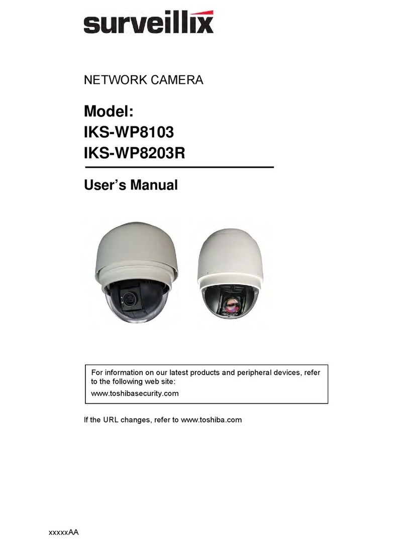
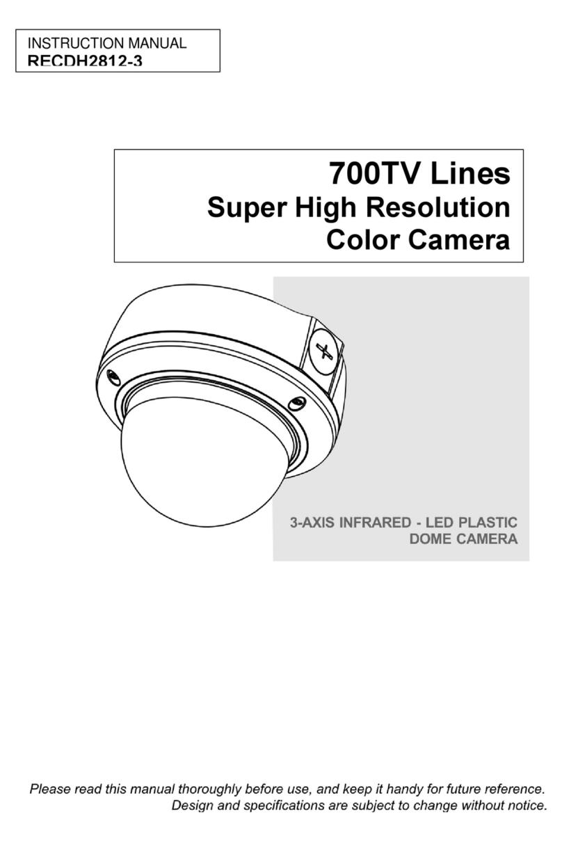
Setek CMQ1862X User manual

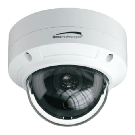
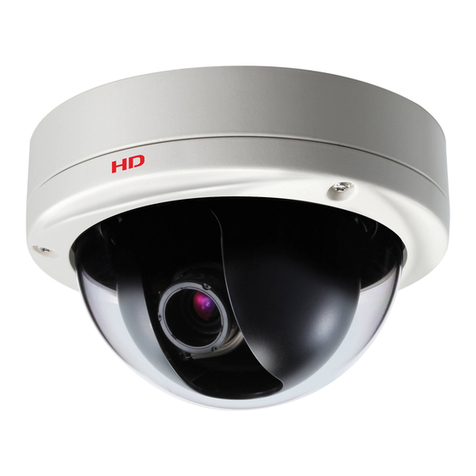
Color Dome Camera
op er at in g in st ru ct io n
Components of your camera
Your camera has the following components:
1. Cover dome: Covers the inner cover, lens, and main
body to protect them.
2. Inner cover: Covers the main body to protect it.
3. Wing locker: Push a long thin screwdriver into its
narrow spot and press it outward when you want to
remove the inner cover.
4. Main body: Includes a lens, a switch board, a PCB
board, screws, and such.
5. IR Leds.
6. Mount bracket: Used as a ceiling or wall fixture. It
ENG is fixed using three long tab screws provided in
the package.
7. Ceiling mount opener: Remove it for line connection
to the ceiling when it is installed on the ceiling.
8. Zoom lever: Using this lever, the lens zoom can be
adjusted and fixed.
9. Focus lever: The lens focus can be adjusted by
rotating it left or right. Rotate it clockwise for fixing.
10.Tilt fixing screw: Using this screw, the slope of the
lens can be adjusted and fixed.
11.Switch board: Includes two kinds of control switches
such as function switches and phase-control switches.
The board has eight function switches in the middle
and two phase-control buttons on each side of the
function switch area.
12.Groove mark: To attach the Main body to the Mount
bracket, align this groove mark on the Main body
with the wide groove in the CAMERA FRONT side
on the Mount bracket.
13.Locker: Used to open or close the Cover dome.
To open the cover dome, press the locker.
14.Lock releaser: Push it outward and rotate the main
body in UNLOCK direction when you want to
remove the Mount bracket from the Main body or to
remove the installed camera from the Mount bracket.
1
2
3
7
6
14
45
89
10
11 12
13
Lens
Setting switches
Overview
This is the high resolution dome camera eqiupped with the most advanced DSP technology and
features humanization design.
1) built-in 3 axis bracket 2)BLC,AGC,AES,MIRROR funtion 3)automatic switching between
color and B/W mode
2) built-in IR LED
Power: DC12V
Feature
Super low power consumption
Auto white balance
Low consunption
Dimensions
SR50mm
HLC/BLC
Day/night function
DNR (Digital Noise Reduction) Varifocal lens
Built-in 3-axis bracket Mirror function
91mm
43mm
128mm

70
1.
you use auto iris lens, select this OFF.
2. BLC(Blacklight Compensation): ON/OFF
BLC ON: When the image is in front of strong background lighting, your camera
allows you to get the clear image.
BLC OFF: Deactivation
3. AGC (Auto Gain Control): ON/OFF
AGC ON: Gain is increased or decreased automatically depending on different
illumination.
AGC OFF: Deactivation
4. (H-MIRROR): when this switch is set to ON, the camera image is reversed
horizontally. If you want to monitor your site using a mirror, you can use this feature
to see the right image.
AES ON/OFF: AE: When you use fix or manual iris lens, select this ON. When
Installing camera
Before installation
You have to check whether the location (ceiling or wall) can bear five times
the weight of your camera.
Don’t let the cable to be caught in improper place or the electric line cover
to be damaged. Otherwise it may cause a break do within or fire.
When installing your camera, don’t allow any person to approach the
installation site. If you have any valuable thing sunder the place, move
them away.
Before installing your camera, you have to read the following cautions:
355
90
Lens rotation
Note: The CAMERA FRONT sign on the Mount bracket should face the camera onitoring area.
Adjusting the camera direction
Ceiling mount opener
1.Press the Locker button on the bottom of your camera and remove the Cover dome
from the Main body using the other hand. The Main body and Inner cover will be
exposed to you.
2.To install and adjust your camera, you have to first remove the Inner cover. To
remove the Inner cover from the Main body, push a long thin screwdriver into the
narrow spot of the Wing locker and press it outward to remove the cover.
3.Remove the Mount bracket from the Main body by rotating the Main body in the
UNLOCK direction while pushing the Lock releaser out ward. If it is not easily
done, rotate the Mount bracket in the LOCK direction while holding small holes
on the Mount bracket.
4.Fix the Mount bracket to the location (ceiling or wall) with supplied three screws.
To install your camera
Tech. Specifications
When the camera is fixed on the ceiling, you
can adjust the camera viewing angle. You can
rotate your camera leftward or rightward
(Panning), and can change the slope of your
camera upward or down ward (Tilting).
In case of panning, the rotation limit of your
camera is set to 355 degree (100 degree
clockwise and 255 degree counterclockwise).
The rotation is stopped by the Stopper inside
of the camera. For panning control, first
unfasten two screws located on the bottom and
In case of tilting, you can change the slope of your camera from zero to 90 degree.
However if the slope angle is under 17 degree, you can encounter a partial image hide
problem. To fix the location after adjusting the tilting angle, use the Tilt fixing screws.
To adjust the focus and zoom of your camera, use the Zoom lever and Focus lever.
When you install the camera on the inclined ceiling or wall, you can rotate the camera
lens to see a correct direction image.
rotate in the direction you want, and then fasten them to fix the camera.
Sensor
TV system
Sync mode
Resolution
S/N Ratio
Minimum
illumination
BLC
AES
Mirror
Power Supply Voltage
Power current
Lens
1/3" High Sensitivity CCD
PAL/NTSC
Internal
52dB(AGC OFF)
OFF/NO
OFF/NO
OFF/NO
DC12V
Without IR
With IR:<230mA(DC12V)
:<100mA(DC12V)
4-9mm
-10 C to 50 C (Within85%RH)
Operation Temperature
-20 C to 50 C (Within85%RH)
Operation Humidity
3-Axis
DNR
IR range Without IR(NO); With IR(20M)
91mm(H) ╳ 128mm(D)
Size(mm)
0TVL
Without IR
With IR
0.01Lux
0Lux (IR ON)
OFF/NO
Gain Control
372g
Weight
Model
Table of contents
