SETRONIC VERONA Boomerang S 6P150 User manual
LINEAR OPTICAL REFLECTING BEAM SMOKE DETECTOR
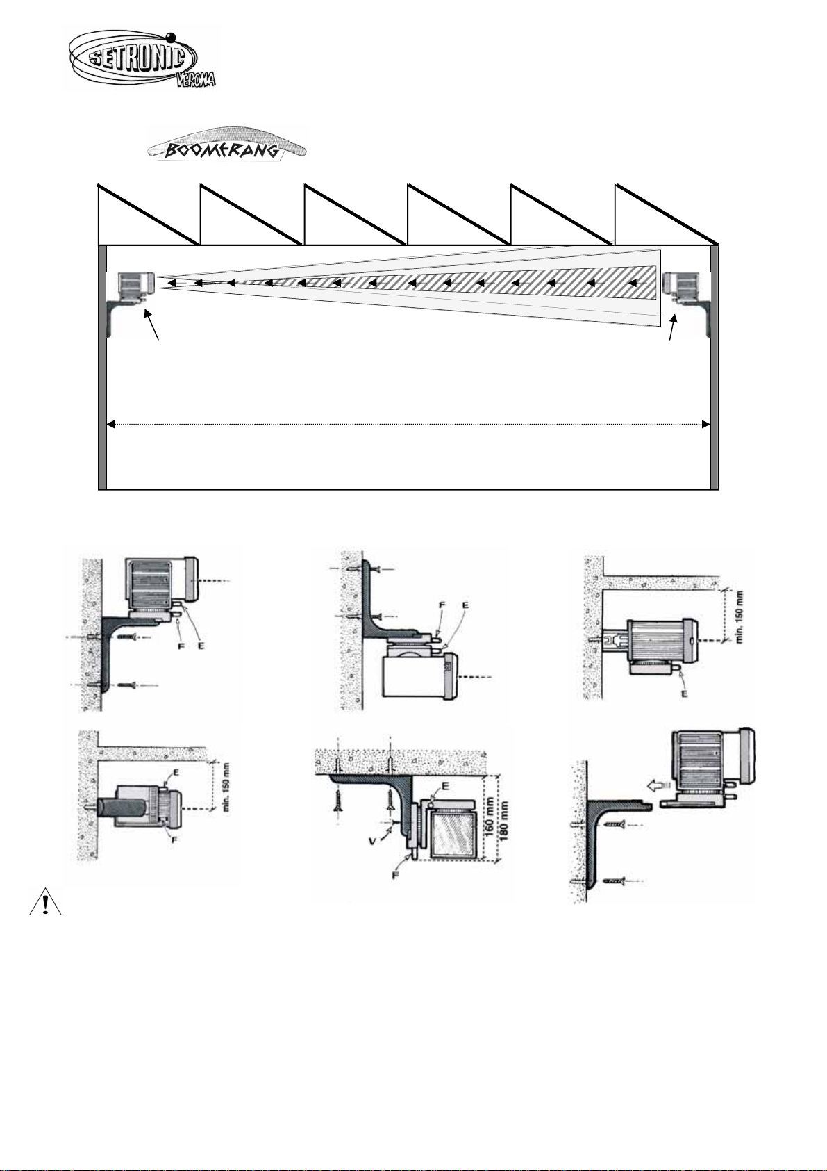
S6P150 distance: min 71m to max 150m
VARIABLE POSITIONING RELATIVE TO THE PLANE THE BRACKET IS FASTENED ON AND
MICROMECHANICAL REFLECTOR DEVICE
ATTENTION
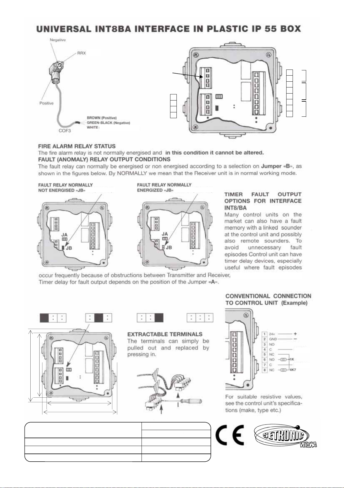
MODEL REQUIRES INTERFACE INT8BA
Before installing the detectors, check the wall or surfaces on which the TRX brackets and micromechanical reflector
device are mounted. They must not be in any way subjected to movement or vibrations during the operation of the
units.
Before installing the units check whether there are any shiny or reflective surfaces crosswise between the beams
along the IR beam path between the TRX and the micromechanical reflector device. If there are, check whether they
interfere with the micromechanical reflector response. If a part of IR light is reflected back by surfaces other than this
reflector device, different TRX positions should be selected.
Do not place this model of detector in warehouses where the goods stored are closer than 1,20m to the ceiling or
roof. Keep the whole path whole detector path distance between the TRX and reflector device as clear as possible.
Avoid detector placement in front of or near to strong electric lights or bright sunlight.
If there are particularly problematic situations, one or more reflector device may be required and a diaphragm could
also be required as an additional accessory to be used according to the instructions provided.
RILEVAZIONE ELETTRONICA ANTINCENDIO
37138 VERONA - Via F. Da Levanto 14 - b
Tel. +39 - 0458347777 Fax +39 - 0458347778
150m MAX
)
)
)
)
)
TRX
STRxBS Micromechanical
Reflector Device
SRFxBS150
126 mm
178 mm
148 mm
220 mm

TRX UNIT BOOMERANG S 6P150
L1Front eject slot
L2Plastic front eject slot cup
AIR intensity adjustment trimmer
BSmoke Led (RED)
* On forewarning
* Blinking alarm
CSmoke threshold adjustment trimmer
DUTA Jack socket
EIR intensity level Led (YELLOW)
* On IR intensity level too low
* Off Normal operating IR power
* Blinking IR intensity level too high
F Power ON Led (GREEN)
V Vertical movement knob
HHorizontal movement knob
REFLECTION DEVICE MODEL 6P150
In this model the reflection device is provided
by a micromechanical reflector device affixed to
the opposite wall.
BOOMERANG S 6P150 ASSEMBLY AND SETTING UP PROCEDURE
1. Fix the TRX mounting bracket and plug in the TRX device. Aim it roughly in the direction of the selected microme-
chanical reflector unit opposite.
2. Fix the reflector micromechanical unit on the opposite side and aim it roughly in the direction of the TRX.
3. Connect the wires as in the wiring diagram in the INT8BA and the TRX. Switch on the system and rotate trimmer “A”
18 turns in a clockwise direction. The Yellow Led can be in one of three possible states: either flashing, or ON, or
OFF. The Led ON means the IR return light beam is too low; if the Led is flashing the IR reflected beam is too
high ; if it is OFF the IR light beam reflected is roughly acceptable. This condition could be a fault in this phase.
4. Align the TRX device using the adjustment knobs “V” and “H”. The required state at the end of this phase is with
the yellow led flashing.
5. Rotate the TRX using adjustment knob “H” in the horizontal plane to the right until the yellow led “E” stops flashing
and goes out. Counting the number of turns of the knob turn back to the left side turning and counting until the yel-
low led stops flashing and goes out. During operation the Smoke red flashing led can light up in alarm mode. This is
normal. Reset by removing the connector to the TRX for min.3 seconds.
6. Divide the number of turns two and turn by that amount towards the middle. You have now found the centre of the
IR beam in the horizontal plane. Repeat the above procedure using knob “V” for finding the centre of the IR beam in
vertical plane. In this situation the yellow Led must be flashing and the trouble interface relay will also operate ON/
OFF intermittently. This state is essential in this phase.
7. Repeat the procedure in 6 above for the micromechanical reflection device at the opposite position finding the
centre of the two axes looking from the opposite side at TRX’s yellow led (E) i.e. ON-OFF-Flashing.
8. Now , for the micromechanical reflection device, cover the reflector with a piece of card or paper. Looking toward the
TRX unit, the yellow Led will flash without covering. When you cover the micromechanical reflection device the
TRX switches off the flashing yellow led and lights the ON light continuously. After removing the obstruction the yel-
low led will flash again. If it does not, check whether there is any shiny reflecting surface along the IR path between
the TRX and reflector device.
9. When both devices are aligned and the yellow TRX device led is flashing, rotate the trimmer “A” anticlockwise until it
stops flashing and goes out, When the led switches off it means the IR strength is accepted by the TRX. Half turn
the trimmer “A” clockwise with the led OFF before replacing the front cover and the slot cup.
A
B
C
D
E
F
H
V
L1
Clockwise
Anticlockwise
+
–L2
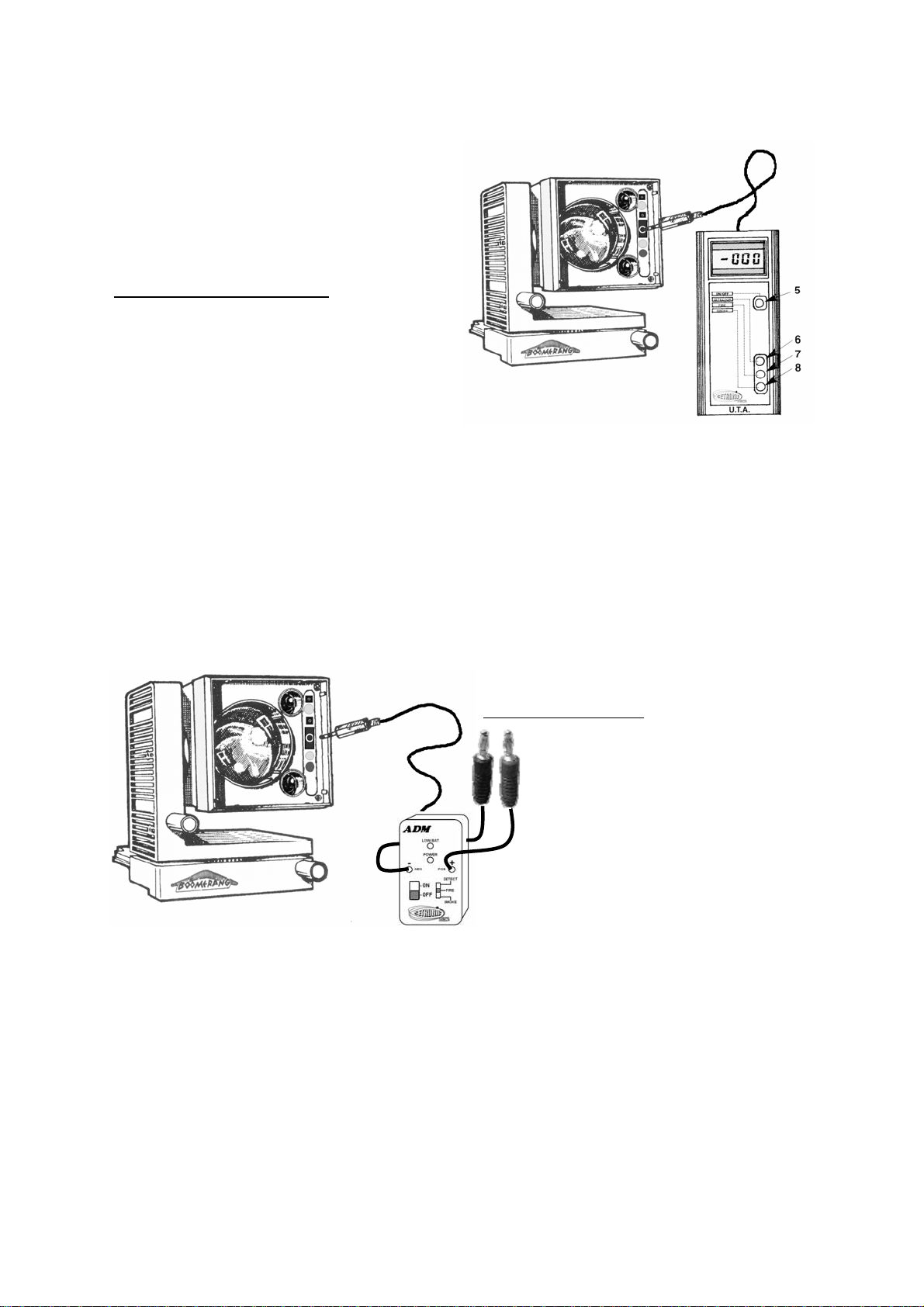
CALIBRATION PROVIDED BY UTA CONTROL DEVICE
The Boomerang TRX device must be adjusted by
mean of UTA control device or an ADM adapter and
multimeter. The sensitivity smoke threshold is set
up in the factory at 600 divisions. Because building
noise can be associated with various sensitivity lev-
els, and in order to avoid any unwanted alarms, the
correct calibration procedure must be followed using
the devices suggested.
If you use UTA calibration meter:
a Insert the jack plug in the TRX socket. Switch on
the UTA device and select “detector” mode (6).
b Wait for some minutes and read the LCD’s peak
noises value displays. This procedure must be
carried out while all the interference factors (hot
air movements, airborne dust, lights etc) are pre-
sent in the building.
c If the peak values read on the UTA give less than
50 divisions, the TRX smoke threshold normally set in the factory (600 divisions) can be accepted. If
the peak levels are higher, the smoke threshold has to be increased to 100 divisions plus every 50
divisions over the first 50 division. (e.g. if there are 100 ‘noise’ divisions read on the UTA in the de-
tector mode you must raise 100 divisions in the smoke threshold 600+100=700. Noise at 150 divi-
sions (600+200=800). Noise at 200 divisions (600+300=900). Noise at 250 divisions
(600+400=1,000).
d In order to raise the threshold select UTA device in smoke mode (8). Turn the trimmer smoke “C” in
a clockwise direction on the TRX device until it reads the UTA values in accordance with the instruc-
tions given in “c” above. Threshold values over 1000 are not suggested unless you have first con-
sulted with out authorised services.
e Switch OFF and disconnect the UTA Jack plug, store the instrument in a cool dry place without its
batteries.
CALIBRATION PROVIDED BY ADM DEVICE
AND MULTIMETER
If an ADM is being used:
a Insert the ADM jack plug in the TRX
socket. Switch on ADM and select
“detector” mode.
Insert the ADM’s plugs in to mul-
timetr respecting the polarity. Set the
multimeter scale to millivolt.
b Wait for some minutes and read the
multimeter’s peak noise values in
milliVolt. This procedure must be
carried out while all the interference
factors (hot air movements, airborne
dust, lights etc) are present in the
building.
c If If the peak values peak read on the multimeter are less than 50 milliVolt, the TRX smoke threshold
normally set in the factory (600 milliVolt) can be accepted. If the peak levels are higher, the smoke
threshold has to increase 100 milliVolt plus every 50 milliVolt over the first 50 milliVolt. (e.g. if there is
a 100 milliVolt noise reading on the ADM in the detector mode you must raise 100 milliVolt in the
smoke threshold 600+100=700. Noise at 150 milliVolt (600+200=800). Noise at 200 milliVolt
(600+300=900). Noise at 250 milliVolt (600+400=1,000).
d To adjust the threshold select the ADM in smoke mode. Turn the trimmer smoke “C” in a clockwise
direction on the TRX device until it reads the multimeter values according to the instructions given in
“c” above. Threshold values over 1000 mV are not suggested unless you have first consulted with
out authorised services.
e Switch OFF and disconnect the ADM Jack plug. Store the ADM in a cool dry place without its
batteries.
Mod. Boom S150-Uk rev. 01
TRX UNIT
9
10
11
12
RRX
Positive
Negative
Shield
24V
Fault
relay
Alarm
relay
POSITION 1
Immediate
POSITION 2
Delay 30”
POSITION 3
Delay 60”
POSITION 4
Delay 90”
1
2
3
4
5
6
7
8
24V
GND
NO
C
NC
NO
C
NC
TERMINALS NOT
USED IN BOOME-
RANG MODELS
104 mm
130 mm
104 mm
130 mm
inserted not inserted
ABSORBTION MAX @ 24 VOLT interface included mA MAX
JB IN JB OUT
NORMAL WORKING 65 78
TROUBLE 87 72
ALARM 78 91
(RRX)
www.setronicverona.com
LINE
LINE
Table of contents
Other SETRONIC VERONA Smoke Alarm manuals


