Severn Trent ADVANCE 200 Series User manual

- 1 - 122.6006.9
Instruction Manual — O-Ring Ejector
Chlorine & Sulfur Dioxide
to 500 PPD (10 kg/h)
100 PPD (2 kg/h) Maximum 250 PPD (5 kg/h) Maximum
500 PPD (10 kg/h) Maximum

122.6006.9 - 2 -
Theseinstructionsdescribetheinstallation,operationandmaintenanceofthesubjectequipment. Failuretostrictlyfollow
these instructions can lead to an equipment rupture that may cause significant property damage, severe personal injury
andevendeath. If you do not understand these instructions, please callSevernTrent Water Purification (STWP), Inc. for
clarification before commencing any work at +1 215 997 4000 and ask for a Field Service Manager. Severn Trent Water
Purification,Inc.reservestherights tomakeengineering refinementsthatmay notbedescribed herein. Itisthe responsibility
of the installer to contact STWP Inc. for information that cannot be answered specifically by these instructions.
Any customer request to alter or reduce the design safeguards incorporated into STWP Inc. equipment is
conditioned on the customer absolving STWP Inc. from any consequences of such a decision.
STWPInc.hasdevelopedtherecommendedinstallation,operatingandmaintenanceprocedureswithcarefulattention to
safety. In addition to instruction/operating manuals, all instructions given on labels or attached tags should be followed.
Regardlessoftheseefforts,itisnotpossibletoeliminateallhazardsfromtheequipmentorforesee every possible hazard
thatmayoccur. It istheresponsibilityoftheinstallerto ensure that the recommended installation instructions are followed.
It is the responsibility of the user to ensure that the recommended operating and maintenance instructions are followed.
Severn Trent Water Purification, Inc. cannot be responsible for deviations from the recommended instructions that may
result in a hazardous or unsafe condition.
STWP Inc. cannot be responsible for the overall system design of which our equipment may be an integral part of or any
unauthorized modifications to the equipment made by any party other that STWP Inc.
STWP Inc. takes all reasonable precautions in packaging the equipment to prevent shipping damage. Carefully inspect
each item and report damages immediately to the shipping agent involved for equipment shipped “F.O.B. Colmar” or to
STWP Inc. for equipment shipped “F.O.B Jobsite”. Do not install damaged equipment.
SEVERN TRENT WATER PURIFICATION INC., COLMAR OPERATIONS
COLMAR,PENNSYLVANIA, USA
IS ISO 9001: 2000 CERTIFIED

- 3 - 122.6006.9
TABLE OF CONTENTS
1 INTRODUCTION.................................................................................................................. 4
1.1 General ...................................................................................................................... 4
1.2 Warranty .................................................................................................................... 4
1.3 Specifications............................................................................................................. 4
2 OPERATION ........................................................................................................................ 5
2.1 General ...................................................................................................................... 5
2.2 Installation................................................................................................................... 5
2.3 EjectorVacuum .......................................................................................................... 6
2.4 Piping......................................................................................................................... 6
2.5 Vacuum Connections.................................................................................................. 6
3 START-UP............................................................................................................................ 7
3.1 VacuumCheck ........................................................................................................... 7
4 SHUTDOWN........................................................................................................................ 8
5 SERVICE ............................................................................................................................. 9
5.1 NozzleCleaning.......................................................................................................... 9
5.2 O-RingReplacement .................................................................................................. 9
5.3 DiaphragmReplacement......................................................................................... 10
5.4 FunctionalTest......................................................................................................... 10
5.5 RecommendedTorque Values ................................................................................. 10
6 TROUBLESHOOTING CHART ......................................................................................... 14
7 FIGURES
1 Gas Feeder System Flow Diagram............................................................................. 5
2 100 PPD (2 kg/h) Ejector.......................................................................................... 11
3 250 PPD (5 kg/h) Ejector.......................................................................................... 12
4 500 PPD (10 kg/h) Ejector........................................................................................ 13

122.6006.9 - 4 -
1 INTRODUCTION
1.1 General
TheADVANCE®ejectorsare expertly engineered and carefully tested to assureyearsofsatisfactory
operation.Theyareconstructedofthefinestmaterialsavailableforgasservice.Correctinstallationand
propercarewillensurebestoperation. Read instructions carefully and save for futurereference.
Thisinstructionmanualonlycovers our standard O-Ring ejector(Reference122.3001).Ifanotherejector
isused,referenceoneofthefollowing:
Diaframless-122.4001,122.3011.
Anti-siphon-122.3013,122.3012.
VariableOrifice-122.3010and 122.6050.
NOTE:TheSeries200O-RingejectorsaredesignedforusewithSeries200gas feeders.
1.2 Warranty
SeeBulletin005.9001fortheADVANCE®equipmentwarranty.
1.3 Specifications
1.3.1 Gas Flow
Differentinlet nozzle and diffusercombinationsareavailablefortheejectors.Yourparticularcombination
waschosenforyourapplication.
a. Auniversaldiffusercan be used fourdifferentways; spray diffuser, open-end diffuser,
3/4" threaded connection, or 1" hose connection. Choose the type suited for the installation
(spray is recommended for good mixing). If other than spray is desired, modify by cutting off
the closed end.
b. Theejector(nozzleandcheckvalveassembly)maybelocatednearthevacuumregulator.A
wallmountingbracketisavailableforfieldassembly,andtheuniversaldiffusercanbemodified
forapipe or hose connection.
c. Theentirediffuser-ejector assembly may be submersed in an open channel or tank.
d. Diffusertubeswithcorporationstopscanbesuppliedforeitherclose-coupledorremote
ejectors.
e. Corporationstopsarerecommended for high pressurepipelineapplicationsandperforatedpipe
diffusersarerecommendedforgoodmixinginopentanksorchannels.
1.3.2 BackPressure
Maximum back pressure at the point of application is 19 psig (1.3 bar). High pressure systems
20 to 140 psig (1.4 to 10 bar) can be accommodated with a high pressure ejector. Consult
factoryifhigherthan140psig(10 bar) back pressures are required.
yticapaCeziSgnibuTmuucaVelzzoNtelnIresuffiDteltuO
DPP001 )h/gk2( "8/3 "2/1 "8/5
lasrevinu/esoh"1 daerht"4/3 elam
TPN"4/3-lasrevinU ro,dne-neporoyarps,daerht esoh"4/3,esoh"1
DPP052 )h/gk5( "2/1 "8/5 daerht"4/11 esoh"2/11 dae
rht"4/11 esoh"2/11
DPP005 )h/gk01( "8/5daerht"4/11 esoh"2/11 daerht"4/11 esoh"2/11

- 5 - 122.6006.9
2 OPERATION
2.1 General
Theejectorisdesignedto complement Severn Trent Services Series 200vacuumregulators. The
ejectoristheheartofthe system providing the vacuum necessary to operate the vacuum regulator.The
diaphragm ejector is to be used in continuous feed applications.
2.2 Installation - Figure 1
The ejector may be installed in any position, since the check valve is spring actuated.
(However,downwardwater flowmaycausecavitationandpoorvacuum).
Thepoint of injection should be carefullychosen so the water pressure intowhich the gas is fed, isaslow
as possible. If the ejector is installed in a pipe, the ejector-diffuser shouldnot beinstalledinthetopof the
pipe where gas may discharge and collect in an emptyarea of thepipe. Diffuser penetrationinto thepipe
should not exceed 1/3 of the diameter of the pipe.
Proceedasfollowstoinstallpipe mounted close-coupled diffuser and ejector.
2.2.1 Unscrew the diffuser from the assembly. Do NOTinstall the ejector with the diffuser attached,
ordamagemayoccur.
2.2.2 Put Teflon tape on the diffuser pipe threads and screw the diffuser into the pipe by hand.
Tighten carefully with pliers. (Make sure that the holes in the spray tube diffuser are in the
main stream.)The endofanopen-end typediffuser shouldnot allow strong chemical solution
to come in contact with pipe or fittings. (This will cause serious corrosion.
Figure1-GasFeedSystemFlowDiagram

122.6006.9 - 6 -
2.2.3 Reconnectnozzleandcheck valve assembly to diffuser. The nozzle may extend through the
assembly from either side. Agasket should be on each side. Screw the nozzle into the diffuser
HAND TIGHT. (The check valve assemblymay be installed in any position.)
2.2.4 Othertypes of diffuser and ejector installations maybe desired for certain applications:
a. Theejector(nozzleandcheckvalveassembly)maybe located near the vacuum regulator.
Awallmounting bracket is available forfieldassembly, and the universal diffusercan be
modifiedforapipeorhoseconnection.
b. Theentirediffuser-ejectorassemblymaybe submersed in an open channel or tank.
c. Diffusertubeswithcorporationstopscanbesuppliedforeither close-coupled or remote
ejectors.
2.3 Ejector Vacuum
Theejectorcreatesavacuumonlywhensufficientpressure differential exists between the ejector inlet
waterversusthewateroutletpressure.
For example, if the diffuser were discharging into an empty basin (zero back pressure), the supply
pressure to the nozzle requires about 25 psig (2 bar) to create enough vacuum to operate a 50 PPD
(1kg/h)vacuumregulator.Alowersupplypressureorahigherbackpressurewouldreducethe gas
flowrate.
Thenforeach 1 psig (0.07 bar) of back pressure above zero, thesupplypressure must be increased
about 2 to 3 psig (0.1 to 0.2 bar) above 25 psig (2 bar).Aback pressure of 10 psig (0.7 bar) would
thereforerequireabout55psig(4bar) supply pressure in order to operate the 50 PPD (1 kg/h) vacuum
regulator.Also, the water supply line to the nozzle must be large enough to allow sufficient water flow
(3/4"or larger pipe is recommended) and minimize friction losses.
2.4 Piping
For most installations, the ejector water supply line should be brought to within 4-6 ft. (1-2 m) of the
nozzlewithrigidcopperor iron pipe.AshutoffvalvefollowedbyaY-strainer, and a hose adapter or pipe
unionshouldbeinstalledtoallowremovalforservice. Apressuregauge between theY-strainer and the
ejector can be a useful service tool.
If the hose is used, connect the hose between the hose adapter or pipe union and the ejector nozzle.
Clamp the hose securely at both ends with single or double clamps.
2.5 Vacuum Connections - See Figure 1 and Introduction, Gas Flow section TableA.
Blackpolyethylenetubingisnormallyusedforthevacuumlinebetweenthevacuumregulator and
ejector. Use enough length for each line to allow vacuum regulator movement from one cylinder to
another.
2.5.1 Removetheconnectornutfromthevacuumregulatorconnection and slip onto the tubing. Push
thetubingontotheconnectorand tighten connector nut HAND TIGHT.

- 7 - 122.6006.9
3 START-UP
3.1 Vacuum Check
The ejector, its water supply and solution lines, must be properly installed and checked before operating
thevacuumregulator. Unlesstheejectoriscreating a vacuum, the vacuum regulator will not work.
3.1.1 Disconnectthevacuumtubingfromtheejector.
3.1.2 Opentheejectorwatersupplyvalve.Theejectorshouldnowbeinoperationandcreatinga
vacuum.
3.1.3 Putyourfingeronthevacuumconnectoropeningandfeelthe vacuum. There should be no
doubt that a vacuum exists. If there is no vacuum, be certain the supply pressure is sufficient
andthenozzleorpipingisnotplugged.Correcttheconditionandobtainpropervacuumbefore
proceedingwithvacuum regulatoroperation.(Referencevacuumregulator instructionmanual)
3.1.4 Reconnectthevacuumtubingtotheejector. Leave the ejector running.

122.6006.9 - 8 -
4 SHUTDOWN
WARNING
Before disconnecting or disassembling the ejector, shutdown the system
as described below. Failure to do so may result in serious injury or death.
1. Close the gas supply valve at the pressure source(s) to shut off the gas flow. This is normally the gas
cylinderand/or container valve(s) supplying the gas dispensing (regulator) system. The rate valveonthe
dispensing system meter panel(s) is/are not to be used to shut off the gas flow. The float in the gas
flowmeter(s) should drop to the bottom of the flow meter indicating zero (no gas feed)
2. Continuetheflow of water through the ejector for a few minutesto remove all gas remaining in the feeder,
pressurepipingandvacuum tubing. While the ejector continues to operate remove the vacuum tubingfrom
thegasinletoftheejectortoallowairtoentertheunitfurtherdilutingtheresidualgas. Stop the ejector water
flowand relieve all residual water pressure. Close any water supply and chemical solution valvesto isolate
the ejector.

- 9 - 122.6006.9
5 SERVICE
It is recommended that the Gas Dispensing System be inspected and serviced a minimum of once per year.
Morefrequent service periods may be required dueto: 1) the type, quality and quantityof the gas being handled,
2) the complexity of the gas supply system, 3) the quality and quantity of water or process liquid being used to
operatetheejector(s),and4) operation procedures.
MorefrequentserviceperiodsareespeciallyindicatedwhenventingoftheVRisoccurringduringtheoneyear
operationalperiod. Thisisusuallyindicative of foreign debris holdingtheinletvalveopenordestructionof the inlet
valve parts caused by the gas quality not up to industry purity standards.
Preventative maintenance kits for each of the assemblies are available from the factory. Each kit contains all the
parts and detailedinstructionsthatarerequired for complete maintenance. All o-rings andgasketsthat have been
disturbedduringthedisassemblymustbereplacedduring reassembly in order to insure safe, trouble free opera-
tion. Failure to replace these parts could result in a shortened operation period and bodily injury.
5.1 Nozzle Cleaning
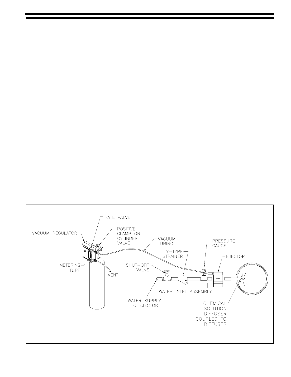
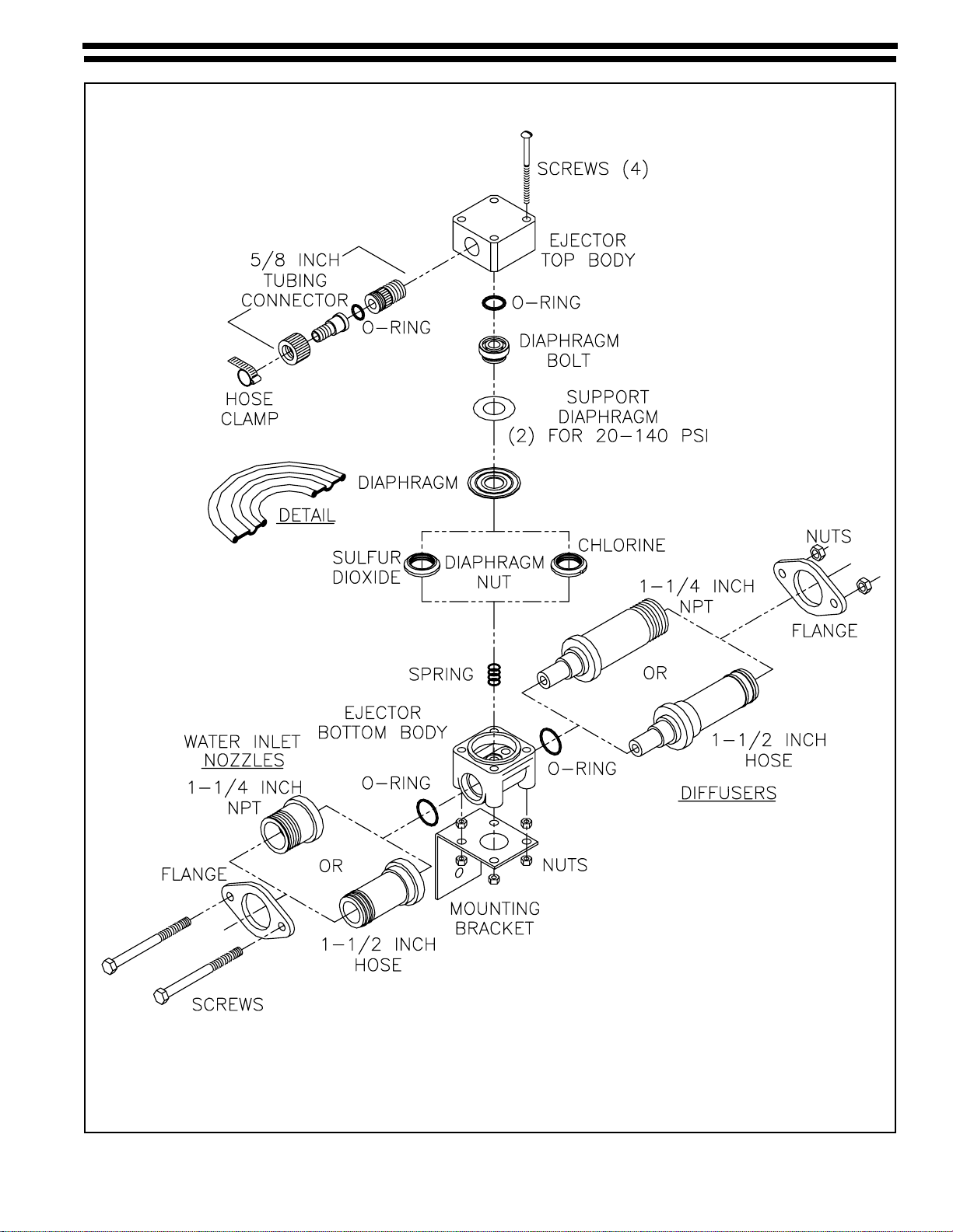
Refer to Figures 1, 2 or 3 and remove the nozzle as follows:
5.1.1 Ejector Disassembly
NOTE: Afterit has been confirmed that all residual gashasbeenevacuatedandwater pressure
hasbeenrelieved,proceedasfollows:
5.1.2 Removethe connecting hose to theejector assembly.
5.1.3 For 100 PPD (2 kg/h) ejectors, rotate the complete ejector body counterclockwise. This loosens
thethreadedportionof the nozzle from the diffuser, eliminatingtheneed for pliers on the hose
connection which may damage the plastic.
For 250 & 500 PPD (5 & 10 kg/h) ejectors, remove the two (2) screws and loosen the flange to
removethenozzle.
NOTE: Nozzlepluggingcanbecausedbyforeignmaterial(pipescale,stone,dirtaccumulation).
This can usually be blown out or pushed out with a wire.
Build-upofdeposits caused by iron, manganese or other material can usuallyberemove by
immersingthenozzleinmuriaticacidandrinsing.Somewatersmaycauseaninoperableejector
andrequirenozzlecleaningeverytwomonths.
5.1.4 To reinstall the nozzle, insert the nozzle through the ejector body and fasten to the dif-
fuser using new gaskets, or o-rings on each side of the ejector body.
NOTE: These parts are plastic and excessive tightening may cause breakage. For 100 PPD
(2 kg/h) ejectors, tighten only hand tight with the ejector body 90° to the left of its final position,
then turn the complete assembly 90°.
5.1.5 Reinstalltheejector supplyhose or pipeand vacuumtubing.
5.2 O-Ring Replacement
Ejectorscontain an o-ring that should be checked and theo-ring/diaphragm bolt assembly replaced as
necessary.
5.3 Diaphragm Replacement - Refer to Figures 2, 3 or 4
5.3.1 Removethefourbolts holding the ejector together to expose the internal parts.
5.3.2 The diaphragm bolt assembly is tightened at the factory, but can usually be separated by using
large,jaw pliers or a vice.Allassembliescontainasupport diaphragm. In high pressure applica-
tions, the assembly includes two thin plastic support diaphragms.
5.3.3 Replacethediaphragmandreassemblethediaphragmnutandbolt.Thesemustbeassembled
tightly using jaw pliers or a special tool to tighten. Install the diaphragm assembly in the recess
ofthetop hole,andboltthe twosectionstogether.(Notediaphragmorientation onFigure2,3 or4).
5.3.4 No adjustments are necessary, but ensure both ends of the spring are square.

122.6006.9 - 10 -
5.4 Functional Test
Whentheejectorisreassembled,afunctional test of the check valve assembly is recommended tocheck
forproperejectorassembly and preventfuturefloodingofthe vacuum regulator.
5.4.1 Donotconnectvacuumtubing to vacuum regulator.
5.42 Turnonwater supply.
5.4.3 Verify vacuum atejector.
5.4.4 Turnwater supply offforapproximately5 minutes. If ejector is assembled properly,no
waterwillleakfromvacuumtubing.
5.5 Recommended Torque Values
Torque values of 14 inch pounds for ejector body screws on units up to 500 PPD/10 kg/h are used at the
factory,andarerecommendedguidelinesforReassemblyofarepaired unit.

- 11 - 122.6006.9
Figure 2 - 100 PPD (2 kg/h) Ejector

122.6006.9 - 12 -
Figure 3 - 250 PPD (5 kg/h) Ejector

- 13 - 122.6006.9
Figure 4 - 500 PPD (10 kg/h) Ejector

122.6006.9 - 14 -
Representedby:
Design improvements may be made without notice.
Severn Trent Services
3000 Advance Lane
Colmar, PA18915 United States
Tel +1 215 997 4000 • Fax +1 215 997 4062
Web: www.severntrentservices.com
E-mail: [email protected]
Copyright 2010 Severn Trent ServicesMAY/10
6 TROUBLESHOOTINGCHART
elbuorTesuaCelbaborPnoitcAevitcerroC
.muucavrotcejetneiciffusnI.1.ytridylppusretawnireniarts-Y.a .wolooter
usserpylppuS.b .hgihooterusserpkcaB.c yllufton,deilppusfi,evlavnoituloS.1 .nepo yllaitrap,tneserpfi,eniln
oituloS.2 .dekcolb ).noitativac(wolootyticoleV.d elzzoN.e detcirtserwolF.1 .degamadronrow.2 .eziselzzontcer
rocnI.f .noitallatsnireporpmI.g
reniarts-YnaelC.a ;evlavnoitulosnepO.cdnab tcerroc;enilnoitulosnaelc .noit
idnocerusserpkcab .rotcejeoterusserpesaercnI.d .taorhtro/dnaelzzonnaelC.g-e dnanoitcesecivreSeeS 1003.321
nitellub
retemwolfdedoolF.2.gnir-orotcejeehtnotriD.a mgarhpaiddegamadronroW.b noitacilppareporpmI.c
rotcej
eecalperronaelC.a .noitcesecivreSeeS.gnir-o .mgarhpaidnrowecalpeR.b .noitcesecivreSeeS no1003.321nitellub
eeS.c .snoitaredisnocciluardyh .evlavdionelosgnitcawolsaesU.d wefa,rotcejeta,enilmuucavdnetxE ehtwollaotr
otcejeehtevobateef ehtemittxenehtytpmeotretaw .ecivresnidecalpsirotceje
foecafrusgnilaesgniR-O.3 gnidurtx
esiydobpotrotceje .tlobmarhpaidotni
.ylamonalacimehceraR.a htiwydobpotrotcejeecalpeR.a .4-2732-UN/P
Table of contents
Popular Plumbing Product manuals by other brands

Graff
Graff G-11520 L1 Series manual

Hans Grohe
Hans Grohe Novus 71140000 Instructions for use/assembly instructions

Hans Grohe
Hans Grohe Picta 13045000 Instructions for use/assembly instructions

Quadro
Quadro 13 69 Instruction manual and maintenance

Toto
Toto LT650 installation manual

American Standard
American Standard INAX AL-652V Installation & user manual

Franke
Franke XINX617 Installation and operating instructions

Hans Grohe
Hans Grohe Finoris 230 76060 0 Series Instructions for use/assembly instructions

Karibu
Karibu 80910 Building instructions

Gurari
Gurari SABIA 5523 Installation and maintenance instruction

Gessi
Gessi MIMI 31199 manual

Wellis
Wellis Pillar WB00443 manual