SEW-Eurodrive DOP11C User manual

*23089717_0320*
Drive Technology \ Drive Automation \ System Integration \ Services
Operating Instructions
DOP11C Operator Panels
2nd Generation
Edition 03/2020 23089717/EN

SEW-EURODRIVE—Driving the world

Contents
Operating Instructions – DOP11C Operator Panels 3
Contents
1 General information.................................................................................................................. 5
1.1 About this documentation ...............................................................................................5
1.2 Other applicable documentation .....................................................................................5
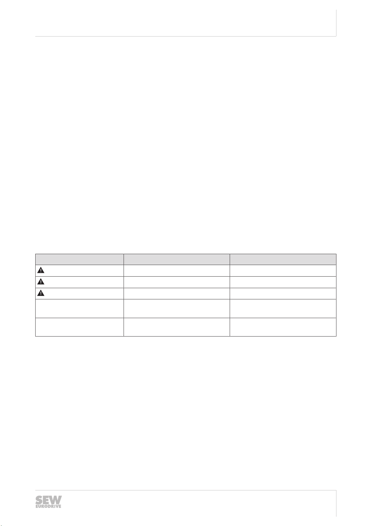
1.3 Structure of the safety notes ...........................................................................................5
1.4 Decimal separator in numerical values ...........................................................................6
1.5 Rights to claim under limited warranty ............................................................................6
1.6 Product names and trademarks......................................................................................7
1.7 Copyright notice ..............................................................................................................7
2 Safety notes .............................................................................................................................. 8
2.1 Preliminary information ...................................................................................................8
2.2 Duties of the user............................................................................................................8
2.3 Target group ...................................................................................................................8
2.4 Designated use ...............................................................................................................9
2.5 Functional safety technology ..........................................................................................9
2.6 Network security and access protection .......................................................................10
2.7 Transportation/storage..................................................................................................10
2.8 Setup/installation...........................................................................................................10
2.9 Installation.....................................................................................................................10
2.10 Electrical connection.....................................................................................................11
2.11 Protective separation ....................................................................................................11
2.12 Startup and operation ...................................................................................................11
2.13 Service/maintenance ....................................................................................................11
3 Device structure ..................................................................................................................... 12
3.1 Type designation and nameplates ................................................................................12
3.2 Scope of delivery ..........................................................................................................13
3.3 Connections of the operator panel................................................................................14
4 Installation............................................................................................................................... 17
4.1 Installation notes for the basic unit................................................................................17
4.2 UL-compliant installation...............................................................................................18
4.3 Space required for installation ......................................................................................20
4.4 Thickness of mounting plate .........................................................................................20
4.5 Unpacking the operator panel.......................................................................................21
4.6 Mounting the operator panel .........................................................................................21
4.7 Connecting the operator panel......................................................................................23
4.8 Connecting the operator panel to the inverter and engineering PC..............................25
4.9 Connecting a voltage supply.........................................................................................30
5 Startup ..................................................................................................................................... 31
5.1 Starting the operator panel ...........................................................................................31
6 Operation................................................................................................................................. 32
6.1 Opening the service menu ............................................................................................32
7 Service..................................................................................................................................... 33
7.1 Waste disposal..............................................................................................................33
23089717/EN – 03/2020

Contents
Operating Instructions – DOP11C Operator Panels
4
8 Technical data and dimension sheets.................................................................................. 34
8.1 Technical data...............................................................................................................34
8.2 Pin assignment .............................................................................................................40
8.3 Cable.............................................................................................................................42
8.4 Dimension sheets .........................................................................................................46
9 Appendix ................................................................................................................................. 54
9.1 Chemical resistance......................................................................................................54
10 Address list ............................................................................................................................. 57
Index ........................................................................................................................................ 68
23089717/EN – 03/2020

1
General information
About this documentation
Operating Instructions – DOP11C Operator Panels 5
1 General information
1.1 About this documentation
The current version of the documentation is the original.
This documentation is an integral part of the product. The documentation is intended
for all employees who perform work on the product.
Make sure this documentation is accessible and legible. Ensure that persons respon-
sible for the systems and their operation as well as persons who work on the product
independently have read through the documentation carefully and understood it. If you
are unclear about any of the information in this documentation, or if you require further
information, contact SEW‑EURODRIVE.
1.2 Other applicable documentation
Observe the corresponding documentation for all further components.
1.3 Structure of the safety notes
1.3.1 Meaning of signal words
The following table shows the grading and meaning of the signal words for safety
notes.
Signal word Meaning Consequences if disregarded
DANGER Imminent hazard Severe or fatal injuries
WARNING Possible dangerous situation Severe or fatal injuries
CAUTION Possible dangerous situation Minor injuries
NOTICE Possible damage to property Damage to the product or its envi-
ronment
INFORMATION Useful information or tip: Simplifies
handling of the product.
23089717/EN – 03/2020

1General information
Decimal separator in numerical values
Operating Instructions – DOP11C Operator Panels
6
1.3.2 Structure of section-related safety notes
Section-related safety notes do not apply to a specific action but to several actions
pertaining to one subject. The hazard symbols used either indicate a general hazard
or a specific hazard.
This is the formal structure of a safety note for a specific section:
SIGNAL WORD
Type and source of hazard.
Possible consequence(s) if disregarded.
• Measure(s) to prevent the hazard.
Meaning of the hazard symbols
The hazard symbols in the safety notes have the following meaning:
Hazard symbol Meaning
General hazard
Warning of dangerous electrical voltage
Warning of risk of crushing
1.3.3 Structure of embedded safety notes
Embedded safety notes are directly integrated into the instructions just before the de-
scription of the dangerous action.
This is the formal structure of an embedded safety note:
SIGNAL WORD! Type and source of hazard. Possible consequence(s) if disregar-
ded. Measure(s) to prevent the hazard.
1.4 Decimal separator in numerical values
In this document, a period is used to indicate the decimal separator.
Example: 30.5kg
1.5 Rights to claim under limited warranty
Read the information in this documentation. This is essential for fault-free operation
and fulfillment of any rights to claim under limited warranty. Read the documentation
before you start working with the product.
23089717/EN – 03/2020

1
General information
Product names and trademarks
Operating Instructions – DOP11C Operator Panels 7
1.6 Product names and trademarks
The brands and product names in this documentation are trademarks or registered
trademarks of their respective titleholders.
1.7 Copyright notice
©2020SEW‑EURODRIVE. All rights reserved. Unauthorized reproduction, modifica-
tion, distribution or any other use of the whole or any part of this documentation is
strictly prohibited.
23089717/EN – 03/2020

2Safety notes
Preliminary information
Operating Instructions – DOP11C Operator Panels
8
2 Safety notes
2.1 Preliminary information
The following general safety notes serve the purpose of preventing injury to persons
and damage to property. They primarily apply to the use of products described in this
documentation. If you use additional components, also observe the relevant warning
and safety notes.
2.2 Duties of the user
As the user, you must ensure that the basic safety notes are observed and complied
with. Make sure that persons responsible for the machinery and its operation as well
as persons who work on the device independently have read through the documenta-
tion carefully and understood it.
As the user, you must ensure that all of the work listed in the following is carried out
only by qualified specialists:
• Setup and installation
• Installation and connection
• Startup
• Maintenance and repairs
• Shutdown
• Disassembly
Ensure that the persons who work on the product pay attention to the following regula-
tions, conditions, documentation, and information:
• National and regional safety and accident prevention regulations
• Warning and safety signs on the product
• All other relevant project planning documents, installation and startup instructions,
and wiring diagrams
• Do not assemble, install or operate damaged products
• All system-specific specifications and conditions
Ensure that systems in which the product is installed are equipped with additional
monitoring and protection devices. Observe the applicable safety regulations and leg-
islation governing technical work equipment and accident prevention regulations.
2.3 Target group
Specialist for me-
chanical work
Any mechanical work may be performed only by adequately qualified specialists. Spe-
cialists in the context of this documentation are persons who are familiar with the
design, mechanical installation, troubleshooting, and maintenance of the product who
possess the following qualifications:
• Qualification in the mechanical area in accordance with the national regulations
• Familiarity with this documentation
23089717/EN – 03/2020

2
Safety notes
Designated use
Operating Instructions – DOP11C Operator Panels 9
Specialist for elec-
trotechnical work
Any electrotechnical work may be performed only by electrically skilled persons with a
suitable education. Electrically skilled persons in the context of this documentation are
persons who are familiar with electrical installation, startup, troubleshooting, and main-
tenance of the product who possess the following qualifications:
• Qualification in the electrotechnical area in accordance with the national regula-
tions
• Familiarity with this documentation
Additional qualifi-
cation
In addition to that, these persons must be familiar with the valid safety regulations and
laws, as well as with the requirements of the standards, directives, and laws specified
in this documentation.
The persons must have the express authorization of the company to operate, pro-
gram, parameterize, label, and ground devices, systems, and circuits in accordance
with the standards of safety technology.
Instructed persons All work in the areas of transportation, storage, operation and waste disposal must be
carried out by persons who are trained appropriately. The purpose of the instruction is
to give persons the ability to perform the required tasks and work steps in a safe and
correct manner.
2.4 Designated use
This product is used for operation and diagnostics purposes of industrial and commer-
cial systems.
The product is intended for control cabinet installation in electrical plants or machines.
In case of installation in electrical systems or machines, startup of the product is pro-
hibited until it is determined that the machine meets the requirements stipulated in the
local laws and directives. For Europe, Machinery Directive 2006/42/EC as well as the
EMC Directive 2014/30/EU apply. Observe EN60204-1 (Safety of machinery - elec-
trical equipment of machines). The product meets the requirements stipulated in the
Low Voltage Directive 2014/35/EU.
The standards given in the declaration of conformity apply to the product.
Technical data and information on the connection conditions are provided on the
nameplate and in chapter "Technical data" in the documentation. Always comply with
the data and conditions.
Unintended or improper use of the product may result in severe injury to persons and
damage to property.
A suitable response to communication errors between the product and the controller
must be implemented in the controller. Additionally, suitable measures (e.g. limit
switches, position monitoring) must be implemented to ensure that no damage occurs
as a result of a communication error with the product.
2.5 Functional safety technology
The product must not perform any safety functions without a higher-level safety sys-
tem, unless explicitly allowed by the documentation.
23089717/EN – 03/2020

2Safety notes
Network security and access protection
Operating Instructions – DOP11C Operator Panels
10
2.6 Network security and access protection
A bus system makes it possible to adapt electronic drive technology components to
the particulars of the machinery within wide limits. There is a risk that a change of pa-
rameters that cannot be detected externally may result in unexpected but not uncon-
trolled system behavior and may have a negative impact on operational safety, system
availability, or data security.
Ensure that unauthorized access is prevented, especially with respect to Ethernet-
based networked systems and engineering interfaces.
Use IT‑specific safety standards to increase access protection to the ports. For a port
overview, refer to the respective technical data of the device in use.
2.7 Transportation/storage
Inspect the shipment for damage as soon as you receive the delivery. Inform the ship-
ping company immediately about any damage. If the product is damaged, it must not
be assembled, installed or started up.
If necessary, use suitable, sufficiently dimensioned handling equipment.
Observe the information on climatic conditions in chapter "Technical data" of the docu-
mentation.
Store the operator panel in a dry, dust-free room if you do not install it right away.
2.8 Setup/installation
The following applications are prohibited unless the device is explicitly designed for
such use:
• Operation in a mining facility or outdoors
• Operation in potentially explosive atmospheres and high fire risk areas
• Use in areas with a strong magnetic field
• Use in direct sunlight
2.9 Installation
Install the product according to the accompanying installation instructions.
Place the product on a stable surface during installation. If the product falls down, it
could be damaged.
Route high-voltage cables, signal cables and supply cables separately from one an-
other.
Make sure that the voltage and polarity of the current source are correct before you
connect the product to the current supply.
To prevent scratches on the touchscreen of the product during delivery, the touch-
screen has a laminated protective film. To avoid static electricity damaging the
product, only remove the protective film from the glass after the installation.
23089717/EN – 03/2020

2
Safety notes
Electrical connection
Operating Instructions – DOP11C Operator Panels 11
2.10 Electrical connection
Familiarize yourself with the applicable national accident prevention regulations before
working on the product.
Perform electrical installation according to the pertinent regulations (e.g. cable cross-
sections, fusing, protective conductor connection). The documentation at hand con-
tains additional information.
Ensure that all of the required covers are correctly attached after the electrical installa-
tion.
Protective measures and protection devices must comply with the regulations in force.
2.10.1 Required preventive measure
Make sure that the product is correctly attached to the ground connection.
2.10.2 Required protection devices
Make sure the product is protected against overload and short circuit by an overcur-
rent protection device.
2.11 Protective separation
The product meets all requirements for protective separation of power and electronics
connections in accordance with EN 61800-5-1. To ensure protective separation, all
connected circuits must also meet the requirements for protective separation.
2.12 Startup and operation
Observe the safety notes in the chapters Startup and Operation in the documentation.
Always keep the operator panel clean.
The openings in the housing are designed to allow air to circulate and must not be
covered over. Make sure that no liquids enter the openings. This may lead to a fire or
cause the equipment to become live.
Do not control any emergency stop functions and other safety functions with the oper-
ator panel.
Make sure that the touchscreen is not touched by any sharp objects.
Bear in mind that the operator panel is ready for operation even if the backlighting is
no longer illuminated, which means that entries made on the touchscreen will still be
registered.
2.13 Service/maintenance
Use only spare parts and accessories manufactured according to the specifications of
SEW‑EURODRIVE. SEW‑EURODRIVE is not liable for modifications, changes, addi-
tions and / or alterations to the product.
Clean the touchscreen and face of the operator panel with a soft cloth and mild clean-
ing agent.
23089717/EN – 03/2020

3Device structure
Type designation and nameplates
Operating Instructions – DOP11C Operator Panels
12
3 Device structure
3.1 Type designation and nameplates
3.1.1 Sample type designation
Example: DOP11C-51
Type DOP DOP = Drive Operator Panel
Generation 11C
Size 5TFT-/LCD display with 5-inch screen diagonal
Design 11 = Plastic
2 = Aluminum
The following sizes and designs of the operator panel are available:
• Operator panels in design ..1
– 51 = 5inches, 800x480 pixels (64000 colors)
– 71=7inches, 800x480 pixels (64000 colors)
– 101=10.1inches, 800x480 pixels (64000 colors)
• Operator panels in design ..2
– 42=4.3inches, 480x272 pixels (64000 colors)
– 72=7inches, 800x480 pixels (64000 colors)
– 102=10.1inches, 1024x600 pixels (262000 colors)
– 122=12.1inches, 1280x800 pixels (262000 colors)
– 152=15.4inches, 1280x800 pixels (262000 colors)
INFORMATION
For more information on data of the operator panels, refer to chapter "Technical
data"(→234).
23089717/EN – 03/2020

3
Device structure
Scope of delivery
Operating Instructions – DOP11C Operator Panels 13
3.1.2 Example nameplate
The nameplate is attached to the rear of the device.
29812261515
3.2 Scope of delivery
Included in the delivery:
• DOP11C operator panel
• Installation material
• Connector for DC 24V, 5mm, 3-pin
• Installation instructions
23089717/EN – 03/2020

3Device structure
Connections of the operator panel
Operating Instructions – DOP11C Operator Panels
14
3.3 Connections of the operator panel
3.3.1 Connections on the underside
Below, you can find a description of the connections on the underside of the different
designs of the operator panel. For detailed information, refer to chapter "Technical
data and dimension sheets"(→234).
Connections of DOP11C-51, -71, -101
18014407502889355
Item Connection Description
[1] Voltage supply DC24V (DC18–32V)
[2] COM1/2 interface
Communication ports (serial, 9-pin D-sub)
• COM1: RS232
• COM2: RS422 or RS485
[3] Ethernet interface (LAN) 1 x 10/100 Base-T (shielded RJ45)
[4] COM3/4 interface
Communication ports (serial, 9-pin D-sub)
• COM3: RS232
• COM4: RS422 or RS485
Connections of DOP11C-42, -72
19269744907
Item Connection Description
[1] Voltage supply DC24V (DC18–32V)
[2] Ethernet interface
(LANA) 1 x 10/100 Base-T (shielded RJ45)
[3] COM interface
Communication ports (serial, 9-pin D-sub):
• COM1: RS232
• COM2: RS422 or RS485
• COM3: RS4851)
NOTE: To operate several communication ports
simultaneously, use the CAB150 adapter cable.
Refer to chapter "CAB150 adapter
cable"(→244) for detailed information on the
Wcable.
1) COM3 can only be used if COM2 is a RS485 connection.
23089717/EN – 03/2020

3
Device structure
Connections of the operator panel
Operating Instructions – DOP11C Operator Panels 15
Connections of DOP11C-102, -122, 152
19270735755
Item Connection Description
[1] Voltage supply DC24V (DC18–32V)
[2] USB interface 1xUSB host 2.0, maximum output current
500mA1)
[3] Ethernet interface
(LANA) 1 x 10/100 Base-T (shielded RJ45)
[4] Ethernet interface
(LANB) 1 x 10/100 Base-T (shielded RJ45)
[5] COM interface
Communication ports (serial, 9-pin D-sub)
• COM1: RS232
• COM2: RS422 or RS485
• COM3: RS4852)
NOTE: To operate several communication ports
simultaneously, use the CAB150 adapter cable.
Refer to chapter "CAB150 adapter
cable"(→244) for detailed information on the W
cable.
1) Another USB host 2.0 is located next to the SD slot on the rear.
2) COM3 can only be used if COM2 is a RS485 connection.
3.3.2 Connections on the rear
Below, you can find a description of the connections on the rear of the different
designs of the operator panel. For detailed information, refer to chapter "Technical
data and dimension sheets"(→234).
19272503307
23089717/EN – 03/2020

3Device structure
Connections of the operator panel
Operating Instructions – DOP11C Operator Panels
16
Item Connection Description
[1] USB interface 1xUSB host 2.0 with a maximum output current of
500mA
[2] SD memory card slot 1 x SD memory card (optional)
INFORMATION
The following operator panels do not have a SD memory card slot:
• DOP11C-51
• DOP11C-71
• DOP11C-101
23089717/EN – 03/2020

4
Installation
Installation notes for the basic unit
Operating Instructions – DOP11C Operator Panels 17
4 Installation
WARNING
Electric shock due to incorrect installation.
Severe or fatal injuries.
• Observe the safety notes in the chapter "Installation"(→210).
INFORMATION
Place the device on a stable surface during installation. If the device falls down, it
could be damaged.
4.1 Installation notes for the basic unit
4.1.1 Separate cable ducts
Route power cables and signal cables in separate cable ducts.
4.1.2 Cable cross sections
• Voltage supply: Cable cross section according to nominal input current.
• Signal lines:
– 1 core per terminal 0.20mm2–0.75mm2 (AWG 20–17)
– 2 cores per terminal 0.20mm2–0.75mm2 (AWG 20–17)
4.1.3 EMC-compliant installation
• Use shielded signal cables only.
• Connect the shield by the shortest possible route and make sure it is grounded
over a wide area at both ends. Ground one end of the shield using an interference
suppression capacitor (220nF/50V) to avoid ground loops. If using double-shiel-
ded cables, ground the outer shield on the control side and the inner shield on the
other end.
The following figure displays examples of correct shield connections using a metal
clamp (shield terminal) or metal Pg cable gland:
23089717/EN – 03/2020

4Installation
UL-compliant installation
Operating Instructions – DOP11C Operator Panels
18
9007200661451659
• You can also use grounded sheet-metal ducts or metal pipes to shield the cables.
Route the power and signal cables separately.
• Ground the device using the built-in connector for a voltage supply of 24 V.
4.2 UL-compliant installation
INFORMATION
Due to UL requirements, the following chapter is always printed in English indepen-
dent of the language of the documentation.
4.2.1 UL and cUL installation
Validity
This section is only valid for UL labeled panels.
Suitability
• This equipment is suitable for use in Class 2 non-hazardous locations only.
• Combinations of equipment in your system are subject to investigation by the local
authority having jurisdiction at the time of installation.
• All devices have to be supplied by a Class 2 power supply.
Expansion units
Only UL and cUL approved expansion units are allowed to be connected to the port
designated "EXPANSION". At the moment there are no such units evaluated or al-
lowed.
Battery
Battery may explode if mistreated. Do not recharge, disassemble or dispose of in fire.
• This product contains a battery; this must only be changed in an area known to be
non-hazardous.
• Replace the battery with a BR 2032 battery. Use of another type of battery may
present a risk of fire or explosion.
23089717/EN – 03/2020

4
Installation
UL-compliant installation
Operating Instructions – DOP11C Operator Panels 19
Flat surface
For use on a flat surface of a type 4X enclosure indoor use only.
Power terminals
Use minimum 75°C copper wire only.
Wiring connections
To make wiring connections to the power supply connector, follow the table with cable
and torque specifications below:
Terminal Block Con-
nector
Wire Size AWG Torque (Lb. ln.)
X1/X100 Phoenix connect-
ors
AWG 30 – 12 5 – 7
X1/X100 Anytek connect-
ors
AWG 24 – 12 3.5
X1/X100 DECA connectors AWG 24 – 12 7
Usage
These devices are Class 2 supplied programmable controllers (industrial PCs) for the
use in industrial control equipment and are intended to be (front) panel mounted (type
12 and 4X for indoor use only).
International protection
The enclosure provides a degree of protection of at least IP20, but when installed in
an apparatus, it should meet IP65.
23089717/EN – 03/2020

4Installation
Space required for installation
Operating Instructions – DOP11C Operator Panels
20
4.3 Space required for installation
The following figure shows the required space for installing the operator panel:
9007208050429835
4.4 Thickness of mounting plate
The thickness of the mounting plate depends on the device design.
4.4.1 Operator panels in design ..1
DOP11C-51 DOP11C-71 DOP11C-101
Maximum thickness 5.5mm 6.5mm
4.4.2 Operator panels in design ..2
DOP11C-42 DOP11C-72 DOP11C-102 DOP11C-122 DOP11C-152
Maximum thickness 11mm 7mm 8mm
23089717/EN – 03/2020
Other manuals for DOP11C
1
This manual suits for next models
8
Table of contents
Other SEW-Eurodrive Control Panel manuals