FSK RHINO 816 User manual


2 FSK-RAP816-V2015.04
Contents
1. System Overview .................................................... 4
System Configuration .............................................................. 4
Control Panel ........................................................................... 5
Remote Keypads ...................................................................... 5
Graphic LCD Remote Keypad .................................................... 5
LED Remote Keypad .................................................................. 5
Wireless Devices ...................................................................... 5
Indoor PIR ................................................................................. 5
Door Contact ............................................................................ 5
Bidirectional Gate Module ........................................................ 5
Relay Module - 4 Channel ......................................................... 5
Remote Control 6 Button .......................................................... 5
Third Party PIR Interface ........................................................... 5
FSK Wireless External PIR ......................................................... 5
Repeater ................................................................................... 5
FSK USB Serial Adapter (FUSA) ................................................ 5
Upload/Download Software .................................................... 5
2. Installation .............................................................. 6
Installation Sequence .............................................................. 6
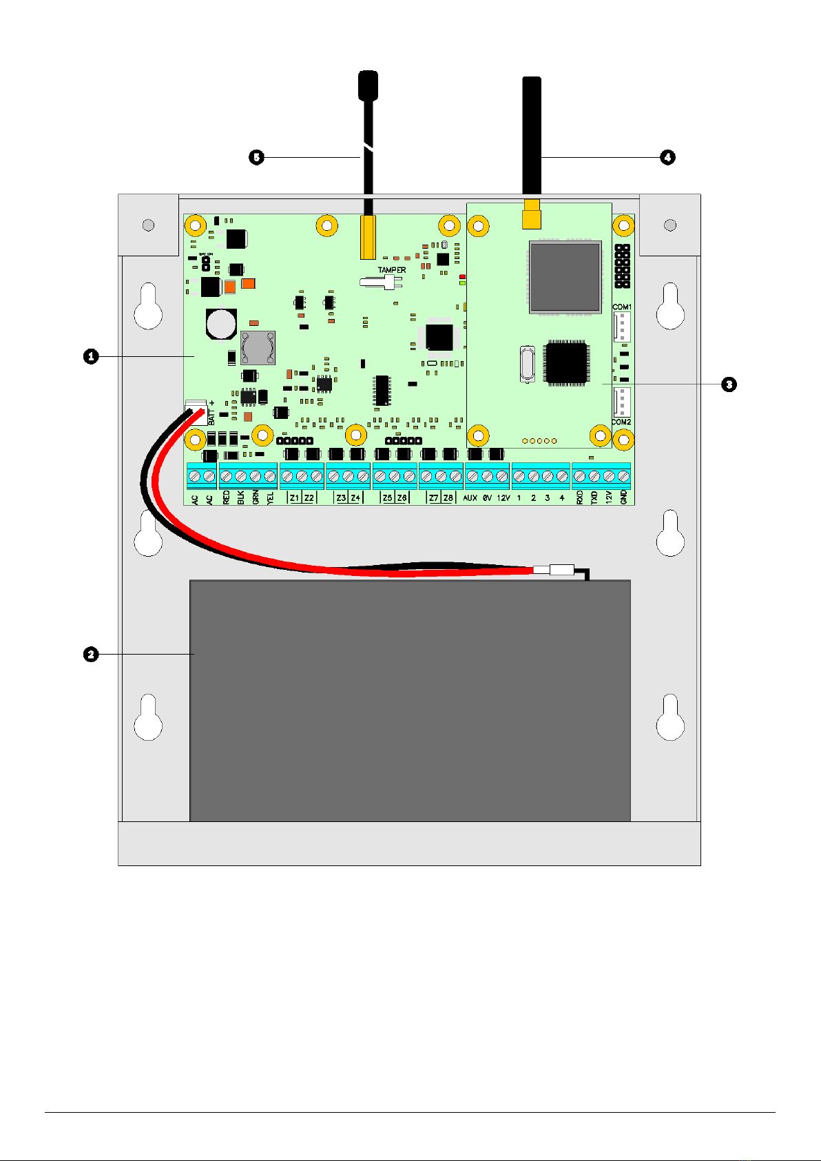
Control Panel ........................................................................... 6
Mounting .................................................................................. 6
Wiring the Control Panel .......................................................... 6
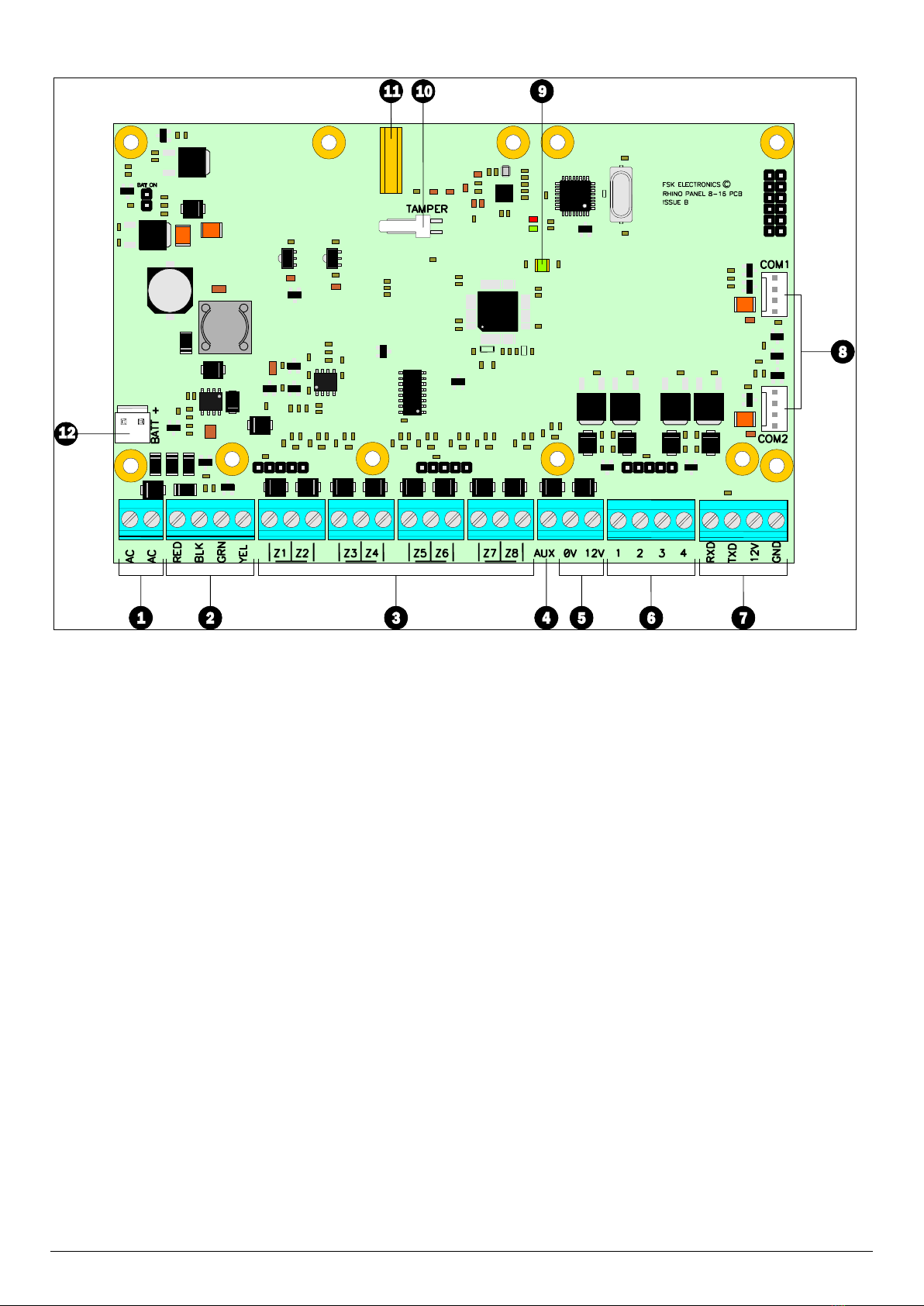
Control Panel Layout ................................................................ 7
Connecting Devices to the Network ......................................... 9
Remote Keypads .................................................................... 10
PCB Layouts ............................................................................ 10
Wiring Detection Devices ...................................................... 10
Normally Closed ...................................................................... 10
Normally Open........................................................................ 10
Single EOL - N/C ...................................................................... 11
Double EOL ............................................................................. 11
Triple EOL................................................................................ 11
Loudspeaker Connections ..................................................... 12
External Sounder/Strobe Connections .................................. 12
0V ........................................................................................... 12
+12 .......................................................................................... 12
Bell (1)..................................................................................... 12
Strobe (2) ................................................................................ 12
Panel Outputs 1 - 4 ................................................................ 12
Configuring Wireless Devices ................................................ 13
On-board Wireless Interface ................................................... 13
RH-100 Wireless Door Contact ............................................... 13
RH-101 Wireless 3rd Party PIR Interface .................................. 13
RH-200 Wireless Indoor Passive ............................................. 14
RH-802 Bidirectional Gate module ......................................... 14
RH-806 Wireless Key Fob ........................................................ 15
Commissioning ...................................................................... 15
3. Programming the Control Panel ........................... 16
Introduction ........................................................................... 16
Easy Mode .............................................................................. 16
Expert Mode ........................................................................... 16
Exiting Engineer’s Program Mode ......................................... 16
Zone Configuration (Easy Mode) ............................................ 17
String Edit - Text Mode ............................................................ 17
Area Configuration (Easy Mode) ............................................ 17
Keypad Configuration (Easy Mode) ........................................ 18
Output Configuration (Easy Mode) ........................................ 18
User Configuration (Easy Mode) ............................................ 18
Expert Mode Menu Navigation .............................................. 19
1. Zone Programming ............................................................. 19
Zone Type ................................................................................ 19
Zone Wiring ............................................................................. 20
Zone Attributes ....................................................................... 20
Zone Areas .............................................................................. 21
Zone Bypass Options ............................................................... 21
Zone Chime ............................................................................. 21
Zone Soak Test ........................................................................ 21
Zone Text ................................................................................ 21
Zone Link ................................................................................. 22
2. Area Options....................................................................... 22
Area Timers ............................................................................. 22
Area Arming Modes ................................................................ 22
Area Configuration Options 1 .................................................. 22
Area Configuration Options 2 .................................................. 23
Area Configuration Options 3 .................................................. 23
Area Timer Control .................................................................. 23
3. System Configuration ......................................................... 24
System Timers ......................................................................... 24
System Counters ..................................................................... 25
Hardware - Volume Levels ...................................................... 25
Hardware - Output Monitoring ............................................... 25
Hardware - Monitoring ........................................................... 26
Speaker Sounds ....................................................................... 26
Configuration 1 ....................................................................... 26
Configuration 2 ....................................................................... 26
Control Timers ......................................................................... 27
Banner Text ............................................................................. 27
Remote Control Labels ............................................................ 27
Area Labels .............................................................................. 27
System Links ............................................................................ 27
Auto Arm and Auto Disarm ..................................................... 28
4. Keypad Configuration ......................................................... 28
Keypad Options 1 .................................................................... 28
Keypad Options 2 .................................................................... 28
Keypad Sounds ........................................................................ 28
Keypad Areas .......................................................................... 29
5. Expander Configuration ...................................................... 29
Expander Areas ....................................................................... 29
Expander Options .................................................................... 29
Expander Sounds ..................................................................... 29
Expander Outputs ................................................................... 30
Expander Output Attributes .................................................... 30
Expander Output Areas ........................................................... 30
Expander Output Link.............................................................. 30
Wireless Outputs ..................................................................... 30
Wireless Output Attributes ..................................................... 30
Wireless Output Areas ............................................................ 30
Wireless Output Link ............................................................... 30

FSK-RAP816-V2015.04 3
6. Panel Outputs and Devices ................................................ 31
Panel Output Type .................................................................. 31
Panel Output Attributes .......................................................... 31
Output Types .......................................................................... 31
00: Global ............................................................................... 31
Group 02: Control Timer ......................................................... 33
Group 03: Remote Control...................................................... 33
Group 04: Link Control ............................................................ 33
Group 10: Zone Count ............................................................ 34
Group 20: Zone Mimic ............................................................ 34
Group 30: Zone Alarm ............................................................ 34
Group 40: Zone Tamper .......................................................... 34
Group 50: Zone Masked ......................................................... 34
Group 60: Zone Fault .............................................................. 34
Group 70: Zone Bypassed ....................................................... 34
Group 80: User Access ............................................................ 34
Communication Port ............................................................... 34
IP Module ............................................................................... 35
7. Communicator (Optional) .................................................. 35
ARC 1-4: Telephone Number .................................................. 35
ARC 1-4: Account Number ...................................................... 35
ARC 1-4: Protocol .................................................................... 35
ARC 1-4: Protocol Options ...................................................... 35
ARC 1-4: Call Sequence/Attempts ........................................... 35
ARC 1-4: Reported Event Groups ............................................ 36
ARC 1-4: Cancel on Success..................................................... 36
ARC 1-4: Areas ........................................................................ 36
ARC 1-4: IP Address ................................................................ 36
ARC 1-4: IP Port Number ........................................................ 36
Options: Auto Test Call Period ................................................ 36
UDL Options ............................................................................ 37
UDL Password ......................................................................... 37
UDL IP Address........................................................................ 37
UDL IP Port.............................................................................. 37
UDL Account Number ............................................................. 37
8. System Users ..................................................................... 37
User Access Code .................................................................... 37
User Type ................................................................................ 37
User Locked By ....................................................................... 38
User Name .............................................................................. 38
User Link ................................................................................. 38
User Areas .............................................................................. 38
9. Utilities .............................................................................. 38
Time and Date ........................................................................ 38
User Menus ........................................................................... 38
Stay Arm 1 1 ....................................................................... 38
Stay Arm 2 2 ....................................................................... 38
Stay Arm 3 3 ....................................................................... 38
Away Arm 4 ........................................................................ 39
Show Chime Log 5............................................................... 39
Show Event Log 6 ................................................................ 39
Clear Notifications 7 ........................................................... 39
Change Code 8 .................................................................... 39
Start Walk Test 9................................................................. 39
Exit Menu 0 ......................................................................... 39
4. SMS Commands .................................................... 40
SMS Introduction ................................................................... 40
SMS Control Function ............................................................. 40
5. MiRhino App ......................................................... 40
6. Log Events ............................................................. 41
7. Status LED Indications .......................................... 43
8. Fault & Status Messages ...................................... 43
9. Default Zones Configuration ................................ 44
10. Status LED Indications .......................................... 46
11. Fault & Status Messages ...................................... 47
12. Specifications ........................................................ 48
Rhino 816 Control Panel ......................................................... 48
Electrical .................................................................................. 48
Environmental ......................................................................... 48
Physical ................................................................................... 48
LED Remote Keypad ............................................................... 48
Electrical .................................................................................. 48
Environmental ......................................................................... 48
Physical ................................................................................... 48
LCD Remote Keypad ............................................................... 48
Electrical .................................................................................. 48
Environmental ......................................................................... 48
Physical ................................................................................... 48
Standards ............................................................................... 49
Safety ...................................................................................... 49
EMC ......................................................................................... 49
Security ................................................................................... 49
Warranty ................................................................................ 49

4 FSK-RAP816-V2015.04
1. System Overview
System Configuration

FSK-RAP816-V2015.04 5
Control Panel
The Rhino 816 control panel is an advanced intruder alarm system
with 8 on-board zones and optional on-board wireless transceiver to
allow support for wireless devices. The system is ideally suited to
domestic and small commercial installations.
The system can be further enhanced by using the Rhino GSM
module which provides both remote signalling and UDL
connectivity.
A choice of either LCD or LED remote keypads is available. Other
features include:
8 programmable on-board wired zone inputs
Another 8 programmable expander wired zone inputs
Or 16 Wireless zone inputs
4 programmable wired outputs (1 Amp rated)
16 programmable wireless outputs
On-board wireless transceiver
Local or remote upload/download
500 event log
Advanced system diagnostics
1.2 Amp power supply
2 serial ports (RhinoBus and USB-Link)
Flash upgradable
Remote Keypads
The Rhino 816 will accept up to a maximum of 4 remote keypads. All
remote keypads require a 4-wire connection to the control panel
using standard alarm cable. The following remote keypad models
are available:
Graphic LCD Remote Keypad
The Graphic LCD keypad features a 128 x 64 pixel display for
showing all zone status and system fault messages. A set of
dedicated system status LEDs for Power, Status and Trouble are also
provided. Other features include:
4-wire connection using standard alarm cable
Internal sounder
Blue Backlit keyboard with adjustable brightness
Full system programming and diagnostics
LED Remote Keypad
The LED keypad features 16 zone status LEDs for zone status and 7
dedicated system status LEDs for AC, Ready, Armed, Bypass, Chime,
Alarm and Fault. Other features include:
4-wire connection using standard alarm cable
Internal sounder
Backlit keyboard
Full system operation (arm, disarm etc.)
The system can only be programmed using a Graphic LCD
keypad or the via the Rhino UDL software.
Wireless Devices
The following wireless devices are available:
Indoor PIR
An indoor 12 metre passive infra-red detector.
Door Contact
A magnetic door contact sensor with an additional zone input for
monitoring other normally closed detectors.
Bidirectional Gate Module
A small module with a single zone input and one output.
Relay Module - 4 Channel
A 4 channel relay module.
Remote Control 6 Button
Key fob for remotely arming, disarming and switching outputs on
and off.
Third Party PIR Interface
A module that interfaces third party PIR’s e.g. Takex.
FSK Wireless External PIR
FSK Dual PIR IP65 Small Form Factor External PIR.
Repeater
A module used to extend the range of wireless devices.
FSK USB Serial Adapter (FUSA)
The FUSA provides USB connectivity between the Rhino 816 and the
host computer. It is required when a direct connection is required
between the Rhino UDL software package and the control panel.
Upload/Download Software
Rhino UDL is a Windows® based software package that can be used
to remotely or locally program and diagnose the Rhino range of
security systems. Features include:
Simple intuitive user interface
Local or remote via modem and IP
System remote control
Advanced system diagnostics
Multi language support

6 FSK-RAP816-V2015.04
2. Installation
Installation Sequence
Before attempting to install the alarm system, read this section.
Once you have an overall understanding of the installation
sequence, carefully work through each step.
1. Design the Layout
Make a rough sketch of the premises to get an idea of where all
alarm detection devices, keypads and other modules are to be
located.
2. Mounting the Control Panel
The control panel must be mounted within the protected area close
to an AC power source.
You must complete all wiring before connecting the battery, or
applying AC to the panel.
3. Install the Remote Keypads
Mount the remote keypads at locations that are easily accessible
during entry and exit from the protected area. Connect the remote
keypads to the control panel.
4. Zone Wiring
Install detection devices and connect to control panel or expander.
5. Other Wiring
Complete all other wiring including external/internal sounders and
telephone line connections.
6. Apply Power to the Control Panel
Once steps 1 to 5 are completed, apply power to the control panel.
First, connect the red battery lead to the positive terminal and the
black lead to negative. Then, connect the AC.
7. Program the System
If available use the Rhino UDL software package to program the
system, if this is not available program this system in accordance
with the procedures in Section 3.
8. Testing the System
Test the system thoroughly to ensure that all features and functions
are operating as required.
Control Panel
Mounting
Mount the control panel on a flat, plumb wall using at least three
appropriate screws. The rear casing has been designed with a
several key-hole slots so that mounting is possible without removing
the Printed Circuit Board (PCB).
It is essential to ensure that none of the fixing slots or cable entries
are accessible after fixing.
Wiring the Control Panel
WARNING: ELECTRICITY CAN KILL
BEFORE connecting the control panel ALWAYS
disconnect the supply at the consumer unit.
If in ANY doubt consult a qualified electrician.
ONLY connect the mains supply from the transformer to
the mains terminal block, NEVER connect the mains
supply directly to the PCB.
The system installation MUST be carried out in
accordance with the national safety standards, for
example EN 60950: 1992.
ALWAYS refer to National Wiring Regulations when
conducting installation.
An appropriate and readily accessible disconnection
device (e.g. an unswitched fused spur) MUST be provided
as part of the installation.
The disconnection device must NOT be fitted in a flexible
cord.
Where identification of the neutral in the mains supply is
NOT possible, a two-pole disconnection device MUST be
used.
The building mains supply MUST incorporate appropriate
short-circuit backup protection (e.g. a fuse or circuit
breaker) of High Breaking Capacity (HBC, at least 1500A).
Use mains cable of adequate carrying capacity for the
rated current (i.e. at least 0.75mm2).
The system installation MUST be carried out in
accordance with the expected norms in the industry, for
example, SAIDSA By-law 5 and By-law 25 (amongst
others).

FSK-RAP816-V2015.04 7
Control Panel Layout
1. Main Printed Circuit Board (PCB)
The main PCB that provides the terminals connection to remote
keypads and detection devices, see PCB Layout on next page for full
details.
2. Standby Battery
The system housing will accept a 12V 7Ah battery to provide
continued operation in the event of an AC mains failure. Connect
the red battery lead to the positive terminal of the battery and then
connect the black battery lead to the negative terminal.
3. GSM Module
An optional Rhino GSM Module can be plugged onto the main PCB.
4. GSM Antenna
Screw in GSM antenna for optional Rhino GSM Module.
5. Wireless Antenna
Screw in wireless antenna for on-board wireless transceiver.

FSK-RAP816-V2015.04 8
PCB Layout
1. AC Input
The two wires from the transformer are connected to these
terminals and supply power the system.
2. Network Connections
The network terminals provide connections to the remote keypads
and zone expanders. The RED and BLK terminals provide power
whilst the GRN and YEL terminals are the data signals.
3. Zone Inputs 1 to 8
Detection devices such as movement sensors, vibration and door
contacts are connected to the zone input terminals. There are
several ways in which to wire a detection device (see page 10). Each
zone is fully programmable, see page 19 for information on
programming zones.
4. Aux Tamper Input
This terminal provides tamper detection for auxiliary devices. If it is
not required link it to 0V.
5. Auxiliary 12V
These terminals provide auxiliary power for the external sounder
and detection devices that require 12V power, e.g., moment
sensors. The auxiliary output is protected by an auto resetting fuse
(PTC) rated at 1.1 Amp).
6. Panel Outputs 1 to 4
These are fully programmable high current (1 Amp), switched
negative supervised outputs. Panel outputs 1 and 2 default to bell
and strobe operation, but can be programmed for other functions if
required, see page 31 for programming details. Each output can also
be programmed for supervision monitoring, see page 25.
Panel output 4 defaults as speaker driver and is used for driving 16Ω
extension loudspeakers (see page 12). If a loudspeaker driver is not
required it can be used as a standard output.
7. RhinoBus Port
The Rhino bus terminals provide connection to Rhino
communication modules.
8. COM Port 1 & 2
COM 1 is provided for local downloading and for third party devices.
COM2 is in parallel with the RhinoBus Port (7) and provides a
different method of connecting compatible modules.
9. Power/Status LED
On steady when either AC or standby battery is present. Flashes
when the communicator is sending data.
10. Lid Tamper Connector
This connector can be used to connect a lid tamper switch to
provide protection for when the enclosure cover is opened.
11. Antenna Screw Connector
This connector provides a screw in connection for the on-board
wireless transceiver antenna.
12. Battery Connections
A 12V rechargeable battery must be connected to these two
terminals in order to provide continuous system operation in the
event of mains failure. The battery output is protected by an auto
resetting fuse (PTC) rated at 1.6 Amp.

FSK-RAP816-V2015.04 9
Connecting Devices to the Network
Before connecting devices to the control panel network, isolate ALL
power from the control panel (AC Mains & Battery). Do not continue
if there is still power present on the control panel.
Connecting devices with power still present on the control
panel may damage the device or control panel and
invalidate any warranty.
Remote keypads are all connected to the network terminals located
at the bottom left hand corner of the control panel and may be
connected serially (daisy chain), in parallel (star) or any combination
of the two.
Network Connections
The network is made up of four terminals incorporating power and
data. To ensure correct operation, all four terminals on the device
must be connected to the corresponding terminals on the control
panel, or previous device. The table below shows each terminal and
its description:
+
RED
+12V Supply
-
BLK
0V Supply
R
GRN
Data Return
D
YEL
Data I/O
Cable Type and Distances
For improved immunity to electrical noise, the use of screened 4
core cable is recommended. The screen should be twisted together
and wired into the (–) terminal at the control panel only.
The maximum recommended distance for devices when using
standard 7/0.2 alarm cable is:
250m for each branch when using the star (parallel)
configuration
When using a daisy chain (series) configuration the maximum
distance will depend on the number of devices connected on
the chain. The more devices that are connected, the shorter
the distance to the last device (this is due to voltage drop in
the cable)
Whichever method of wiring configuration is used, ensure that the
voltage between the ‘+’ and ‘–’ terminals at each device is no lower
than 10.0V when the system is running on the standby battery.
Overcoming Voltage Drop
There are several ways to overcome voltage drop:
Use thicker lower resistance cable. Standard 7/0.2 alarm cable
has a resistance of 8Ω per 100m
Double up on the power connections – this will require using a
6 or 8-core cable rather than a 4-core cable
Install a power supply to power the device locally, remember
to common the two negative connections
Installing a Power Supply
When a power supply is installed, the 0V connections on the power
supply must be connected through to 0V on the control panel and
the +12V connection between the control panel and the device
must be disconnected (see figure below).
The maximum tested network distance is 400m.

10 FSK-RAP816-V2015.04
Remote Keypads
PCB Layouts
LED Remote Keypad
Graphic LCD Remote Keypad
1. Network Connections
The remote keypad is connected to the network terminals located
at the bottom left hand side of the PCB.
2. Address Selection (Led keypad only)
Each remote keypad must be assigned a different address using the
Address selector. Move the jumper to the required position 1, 2, 3
or 4. To assign a keypad number to a graphic LCD remote keypad,
please refer to the graphic LCD keypad manual.
3. Piezo Sounder
The piezo sounder generates low level alarm, key press, and
warning tones. Each type of tone can be enabled or disabled for
each remote keypad, please refer to page 28 for further details.
Wiring Detection Devices
The Rhino 816 provides 8 zones for connecting detection devices
such as movement sensors and magnetic door contacts. Each zone
is fully programmable to allow for maximum flexibility (see page 19
for Zone Programming details). The program options for a zone will
also determine how the zone may be wired. The following wiring
options are available:
Normally Closed
This wiring configuration should be used when connecting detection
devices that only have a normally closed alarm output. Connect the
detector as shown below and ensure that the zone is programmed
for “Normally Closed” operation, see page 20.
Normally Open
This wiring configuration should be used when connecting detection
devices that only have a normally open alarm output. Connect the
detector as shown below and ensure that the zone is programmed
for “Normally Open” operation, see page 20.

FSK-RAP816-V2015.04 11
Single EOL - N/C
This wiring configuration should be used when connecting detection
devices that only have a normally closed alarm output. Connect the
detector as shown below and ensure that the zone is programmed
for “Single EOL – N/C” operation, see page 20.
Double EOL
This wiring configuration should be used when connecting detection
devices that have a normally closed alarm and tamper output.
Connect the detector as shown below and ensure that the zone is
programmed for “Double EOL” operation, see page 20.
Triple EOL
This wiring configuration should be used when connecting detection
devices that support triple EOL configuration, this will allow the
system to monitor alarm, tamper fault and mask. Connect the
detector as shown below and ensure that the zone is programmed
for “Triple EOL” operation, see page 20.

12 FSK-RAP816-V2015.04
Loudspeaker Connections
The Rhino 816 has a loudspeaker output capable of driving one 16Ω
or two 8Ω wired in series as shown below:
The volume level can be programmed, please refer to page 25 for
details. The loudspeaker can also be tested, please refer to page 25
for further details.
External Sounder/Strobe Connections
The following connections are available for connection to an
external sounder/strobe unit:
0V
0V supply. Connect to the 0V (-) supply on the external
sounder/strobe unit.
+12
Positive 12V supply, which is protected by an auto resetting fuse
(PTC) rated at 1.1A. Connect to the +12V (+) supply on the external
sounder/strobe unit.
Bell (1)
Panel output 1 is pre-configured for Bell operation, i.e. it switches to
0V when active. Connect this terminal to the bell trigger input on
the external sounder/strobe unit.
Strobe (2)
Panel output 2 is pre-configured for Strobe operation, i.e., it
switches to 0V when active. Connect this terminal to the strobe
input on the external sounder/strobe unit.
Panel Outputs 1 - 4
The control panel has four programmable outputs, which can be
used to drive auxiliary devices such as LEDs, sounders or relays etc.
(see page 31 for details on programming outputs). Each panel
output is rated at 1 Amp and switches to 0V when active. The figure
bellow shows some wiring examples:

FSK-RAP816-V2015.04 13
Configuring Wireless Devices
This section covers the setting up and installation of wireless
devices.
On-board Wireless Interface
The Rhino 816 has a wireless transceiver that is integrated onto the
main PCB. It allows a support for various wireless devices.
RH-100 Wireless Door Contact
The RH-100 is a professional state-of-the-art wireless door contact
sensor. It has two zones, one on the magnetic (reed) switch and
one on the zone input terminals.
The RH-100 must be allocated to one of the available zones (1-8).
However, if the device is allocated to an on-board wired zone (1-6),
the wired zone input will be disabled.
The figure below show the layout of the RH-100 Wireless Door
Contact:
1. Battery Location
The wireless door contact is powered by a CR2 3V Li-ion battery,
which must be fitted correctly. Please wait 60 seconds after battery
installation for the device to initialise.
2. Tamper Switch
The lid tamper detection switch, this switch is also used when
learning the device onto the system.
3. Activity LED
The activity LED illuminates when the device is transmitting a
wireless signal.
4. Zone Input Terminals
The wireless door contact has two detection inputs. The first is the
magnetic reed switch that is activated by the magnet. The second
requires a voltage free normally closed contact and is wired into
these terminals. Both inputs report back to the same zone on the
control panel. If the zone input is unused it must be linked out.
5. Magnetic Reed Switch
The magnetic reed switch detects the presence of the magnet fitted
to the door.
The Magnetic Reed switch is always in operation. If you
only require the use of the Zone Input Terminals, the
magnet must be held close to the reed switch at all times.
6. Antenna
The wireless antenna used for transmitting the wireless signal.
RH-101 Wireless 3rd Party PIR Interface
The RH-101 is a professional state-of-the-art wireless module that is
specifically engineered to be sub-equipped into other brands of PIR
sensors. It features an Alarm Normally Closed contact as well as a
Tamper Normally Closed contact. The tamper contact is also wired
in series with the internal case tamper contact on the PCB.
The RH-101 must be allocated to one of the available zones (1-16).
However, if the device is allocated to an on-board wired zone (1-8),
the wired zone input will be disabled.
The figure below show the layout of the RH-101 Wireless 3rd Party
PIR Interface:
1. Battery Location
The wireless door contact is powered by a CR2 3V Li-ion battery,
which must be fitted correctly. Please wait 60 seconds after battery
installation for the device to initialise.
2. Tamper Switch
The lid tamper detection switch, this switch is also used when
learning the device onto the system.
3. Activity LED
The activity LED illuminates when the device is transmitting a
wireless signal.
4. Alarm Input Terminals
The normally closed alarm output from the 3rd party detector is
connected to these terminals.
5. Tamper Input Terminals
The normally closed tamper output from the 3rd party detector is
connected to these terminals.
6. Antenna
The wireless antenna used for transmitting the wireless signal.

14 FSK-RAP816-V2015.04
RH-200 Wireless Indoor Passive
The Rh-200 is a professional state-of-the-art motion sensor
engineered with the world's best components and materials,
starting with a HighView™ lens and a top-quality infrared detector.
Next, a patented modern DSP ASIC directly converts the infrared
detector signal into digital form, for best reliability and stability.
Finally, the signal is evaluated by HighBar™ processing, for "best-in-
class" false alarm rejection with excellent intruder detection.
The RH-200 must be allocated to one of the available zones (1-8).
However, if the device is allocated to an on-board wired zone (1-6),
the wired zone input will be disabled.
The figure below show the layout of the RH-200 Wireless Indoor
Passive:
1. Battery Location
The wireless indoor passive is powered by a CR123 3V Li-ion battery,
which must be fitted correctly. Please wait 60 seconds after battery
installation for the device to initialise.
2. Tamper Switch
The lid tamper detection switch, this switch is also used when
learning the device onto the system.
3. Activity LED
The activity LED illuminates when movement is detected and when
the device is transmitting a wireless signal.
RH-802 Bidirectional Gate module
The RH-802 (Single Channel IO Module) is a professional state-of-
the-art wireless 1 Zone Input & Output module. It has specifically
been developed for applications like controlling Gate Motors,
Garage Door Openers, Sprinkler Systems, etc. Due to the fact that it
has both an output and an input function, the output can be used to
control the external equipment and the input zone can be used to
provide physical feedback of the external equipment actual status.
For example the output can be used to control a gate motor and the
input zone can be used to show whether the gate is closed or open
via a wired magnetic reed switch.
The RH-802 must be allocated to one of the available zones (1-8).
However, if the device is allocated to an on-board wired zone (1-6),
the wired zone input will be disabled.
The output is not available when the RH-802 is used with
the Rhino 816 but can be programmed to directly connect
to other devices like FOB or another Bidirectional Gate
Module
The figure below show the layout of the RH-802 Bidirectional Gate
Module:
1. Supply Terminals
The RH-802 must be powered from either a 12V or 24V DC supply.
2. Relay Output
A set of voltage free change over contacts. COM - Common; NC -
Normally Closed; NO - Normally Open.
3. Input
These terminals provide 2 methods for connecting external
equipment:
4. Ground
The ground terminal is connected to - supply terminal for a common
0V reference.
5. Learn Button
This button is used when learning the device onto the system.
6. Relay Control Indicator
This LED indicates if the Relay Control Message has been received.
7. Wireless Activity Indicator
This LED indicates when a radio packet is received or transmitted.

FSK-RAP816-V2015.04 15
RH-806 Wireless Key Fob
Each user maybe assigned a wireless key fob to allow remote
control of the system. The figure below shows the layout of the key
fob:
Standard Remote Control
Beep Remote Control
1. Panic Alarm
This button activates the panic alarm.
2. Away Arm
This button Away Arms the areas allocated to the user
3. Disarm
This button disarms the areas allocated to the user.
4. Stay Arm
This button stay arms the areas allocated to the user.
5. Remote Control 1
This button toggles on and off outputs that are programmed as
“Remote Control 1.
6. Remote Control 2
This button toggles on and off outputs that are programmed as
“Remote Control 2.
7. Activity LED
The activity LED illuminates when the key fob is transmitting a
wireless signal.
Commissioning
Once ALL connections have been made to the control panel and
power is ready to be applied, you should read this section before
continuing.
The control panel leaves the factory programmed with default
settings and when the system is powered up for the first time the
default settings are in use. If the factory defaults need to be
reloaded in future, press “CLEAR, 9 then ENTER” on the graphic
LCD keypad within 10 seconds after powering up the panel.
Connect the black battery lead to the negative (–) terminal of
the standby battery and the red battery lead to the positive (+)
terminal of the standby battery. The green power LED on the
main PCB will light.
If the system enters into an alarm condition, enter the default
master user code 1234. The alarm tone will then stop.
To access the Engineer Programming Menu, enter the default
engineer code 789000. The remote keypads will show:
Program the system as described in the next section
(Programming the Control Panel).
Carry out a walk test as described on page 39. Remember that
some powered detectors (e.g. PIRs and combined technology
detectors) take several minutes to warm up before they
become operational.
Replace the lid and secure with the lid screw supplied - do not
over-tighten.
Press Clear to select “Exit Menu” then Enter to exit the
engineer’s program mode.
Installation is now complete and the system is ready for use. Please
ensure the system users are provided with adequate training on
operating the alarm system.

16 FSK-RAP816-V2015.04
3. Programming the Control Panel
Introduction
This section covers the system programming and it is important that
all engineers read this section carefully so as to familiarise
themselves with the many features and functions of the control
panel. To access the programming menu, enter the factory default
engineer code 789000. If a mistake is made whilst entering the
code, simply re-enter the code correctly.
The system configuration and programming is broken down into
two modes:
Easy Mode
This mode allows access to the most common programmable
features. The following easy modes are available:
1: Zone Configuration
2: Area Configuration
3: Keypads
4: Outputs
5: Users
Expert Mode
This mode allows access to all programmable features. When Expert
Mode is selected from the main menu, each programming option is
accessed by a four digit location number followed by Enter. The
location numbers have been grouped together into logical sections.
The programming sections are as follows:
Section
Page
1 Zone Programming
1 Zone Types
2 Wiring
3 Zone Attributes
4 Reserved
5 Bypass Options
6 Chime Options
7 Soak Test
8 Zone Text
9 Zone Links
19
2 Area Options
1 Area 1 Options
2 Area 2 Options
22
3 System Configuration
1 System Timers
2 System Counters
3 Hardware Options
4 Configuration
5 Control Timers
6 Banner Text
7 Reserved
8 Reserved
9 System Output Links
24
Section
Page
4 Keypad Options
11 Keypad Options 1
12 Keypad Options 2
13 Keypad Sounds
14 Keypad Areas
28
5 Expander Options
10 Expander Areas
11 Expander Options
12 Expander Sounds
2 Expander Output Type
3 Expander Output Attributes
4 Expander Output Areas
5 Expander Output Link
29
6 System Outputs & Devices
1 Panel Outputs
2 Com Ports
3 GSM Configuration
4 TCP/IP Configuration
31
7 Communicator (Optional)
0 ARC 1 - 4 Configuration
1 Options
2 Reserved
3 Reserved
4 UDL Options
35
8 Users
1 User Code
2 User Type
3 User Time Locks
4 User Name
5 User Link
6 User Areas
37
9 Utilities
0 Set Time and Date
38
Exiting Engineer’s Program Mode
To exit the engineers programming menus and return to the normal
disarmed mode:
From Easy Mode, ensure the display is showing the main
menu. Press Clear to select “Exit Menu” then Enter to exit the
engineer’s program mode.
From Expert Mode, ensure the display is prompting you for a
location number, Press 99 Enter to exit the engineer’s
program mode.

FSK-RAP816-V2015.04 17
Zone Configuration (Easy Mode)
The flowchart below shows how to navigate the Zone Configuration
menu. For full description of each option please refer to page 19.
Bypass Options
Key
Bypass Mode
Description
1
S1
Zone bypassed on
Stay 1 mode
2
S2
Zone bypassed on
Stay 2 mode
3
S3
Zone bypassed on
Stay 3 mode
4
M
Zone bypassed
manually
5
A
Zone auto -
bypassed
6
K
Zone Key switch
bypassed
String Edit - Text Mode
This type of data entry is used for entering text such as user names
and zone text. The text is entered in the same way as entering text
on a mobile telephone. Each key is mapped to one or more letters.
Pressing a key will select the first letter, pressing it again will select
the next etc. The table below shows the keys to use and the
characters that are assigned to them:
Key
Characters
1
1
2
A
B
C
2
a
b
C
3
D
E
F
3
d
e
F
4
G
H
I
4
g
h
I
5
J
K
L
5
j
k
L
6
M
N
O
6
m
n
O
7
P
Q
R
S
7
p
Q
r
s
8
T
U
V
8
t
u
V
9
W
X
Y
Z
9
w
X
y
z
0
_
0
.
-
*
#
@
i
Next character
Area Configuration (Easy Mode)
The flowchart below shows how to navigate the Area Configuration
menu. For full description of each option please refer to page 22.

18 FSK-RAP816-V2015.04
Keypad Configuration (Easy Mode)
The flowchart below shows how to navigate the Keypad
Configuration menu. For full description of each option please refer
to page 28.
Output Configuration (Easy Mode)
The flowchart below shows how to navigate the Output
Configuration menu. For full description of each option please refer
to page 31.
User Configuration (Easy Mode)
The flowchart below shows how to navigate the User Configuration
menu. For full description of each option please refer to page 37.

FSK-RAP816-V2015.04 19
Expert Mode Menu Navigation
Expert Mode allows access to all programming options and features.
Each programming location is accessed by entering its four digit
location number followed by Enter. If you don’t know the exact
location you can enter less than four digits and the panel will take
you to the first location that starts with numbers you have entered.
For example if you enter 12 the panel will take you to location 1201
– Zone 01 Wiring Type.
When the panel gets defaulted, configuration settings shown in bold
take effect.
WHEN THE PANEL GETS DEFAULTED, CONFIGURATION
SETTINGS SHOWN IN BOLD THROUGHOUT THE MANUAL
TAKE EFFECT.
1. Zone Programming
This section covers programming of the detection zones, each zone
must be programmed a zone type, wiring type and attributes.
DEFAULT CONFIGURATION SETTINGS FOR ZONES WHEN
THE PANEL IS DEFAULTED BY PRESSING “CLEAR, 9,
ENTER” ARE SHOWN ON PAGE 44.
Zone Type
Each zone must be programmed to the correct type in order for the
correct response.
Locations: 1101 to 1116
Zone 01 to 16: Zone Type.
Entry Mode: Enter 4 digit location followed by Enter, then key
in 2 digit zone type from list below or press i to scroll through list.
When finished press Enter to accept or Clear to cancel.
00 Not Used
Use this zone type for unused zones, as zones programmed as “Not
Used” are not be monitored by the system.
01 Delay 1/Final Exit 1
Use this zone type for the main entry/exit detector, normally a
magnetic contact on the front door. The zone can be activated
during the exit mode without causing a fault. If the system is armed,
activation of the zone will start the Entry 1 Delay timer for the
relevant arm mode.
02 Delay 2/Final Exit 2
Use this zone type for an alternative entry/exit detector. The zone
can be activated during the exit mode without causing a fault. If the
system is armed, activation of the zone will start the Entry 2 Delay
timer for the relevant arm mode.
03 Walk Through
Use this zone type for detection devices along the entry/exit route.
This zone type will allow the user to walk past the detector without
causing a fault during the exit mode or an Intruder alarm during the
entry mode. However, if activated at any other time the zone will
cause an immediate intruder alarm. This zone type will also start the
entry mode when the system is stay armed.
04 Intruder
Use this zone type for detection devices such as PIR’s, vibration
detectors, magnetic door contacts etc. This zone type generates an
intruder alarm if activated when the system is armed.
05 Perimeter
Use this zone type for detection devices such as external PIR’s, IR
beams. This zone type generates an intruder alarm if activated when
the system is armed.
06 Fire
Use this zone type for smoke and heat detectors. This zone type
generates a distinctive fire alarm if activated at any time.
07 PA Silent
Use this zone type for panic buttons. This zone type generates a
silent panic alarm if it is activated at any time.
08 PA Audible
Use this zone type for panic buttons. This zone type generates an
audible panic alarm if it is activated at any time.
09 Medical
Use this zone type for medical alarms. This zone type generates a
medical alarm if it is activated at any time.
10 24 Hour
Use this zone type for detectors that require 24 hour monitoring.
This zone type generates an intruder alarm if it is activated when
the system is armed. If activated during the disarmed state an
internal alarm is generated.
11 Tamper
Use this zone type for tamper protection. This zone type generates a
tamper alarm if it is activated when the system is armed. If activated
during the disarmed state an internal alarm is generated.
12 Exit Terminator
Use this zone type for external push to set buttons. This zone type
terminates the exit delay when activated during exit mode. The
arming mode must be configured for “Exit Terminator” for this zone
type to function.
13 Away Arm Key
Use this zone type for a key switch or lock that has switch contacts.
This zone type will away arm the assigned areas when active and
disarm the assigned areas when healthy. If a “momentary”
operation is required then the “Momentary Keyswitch” attribute
can be assigned, see page 21.
14 Stay 1 Arm Key
Use this zone type for a key switch or door lock that has switch
contacts. This zone type will stay arm (1) the assigned areas when
active and disarm the assigned areas when healthy. If a

20 FSK-RAP816-V2015.04
“momentary” operation is required then the “Momentary
Keyswitch” attribute can be assigned, see page 21.
15 Stay 2 Arm Key
This zone type operates as type 14, but performs a stay arm 2.
16 Stay 3 Arm Key
This zone type operates as type 14, but performs a stay arm 3.
17 Bypass Key
Use this zone type for a key switch or door lock that has switch
contacts. This zone type will bypass all zones with the keyswitch
bypass attribute when active and reinstate them when healthy. If a
“momentary” operation is required then the “Momentary
Keyswitch” attribute can be assigned, see page 21.
18 Security Key
Use this zone type for a key switch. This zone type will disable all
remote keypads from disarming the panel when active and reinstate
them when healthy. If a “momentary” operation is required then
the “Momentary Keyswitch” attribute can be assigned, see page 21.
If you want to change a zone from being a security key to another
zone type, make sure you enable the remote keypads first.
19 Auxiliary
Use this zone type for auxiliary devices, which do not require an
audible alarm response. This zone type generates a silent alarm if
activated at any time.
20 Warning
Use this zone type for monitoring devices that require a warning
indication. This zone type generates a warning (alarm tone on
remote keypad and zone indication) if the zone remains active for
longer than the warning delay time, see page 25 for details.
21 Log/Monitor
Use this zone type for monitoring devices that require an event log
entry. This zone type generates a log entry if activated at any time.
22 Trouble/Fault
Use this zone type for monitoring fault outputs on devices such as
remote power supplies. This zone type generates a fault condition if
it is activated at any time.
23 Counter
Use this zone type for counting the number of activations from a
detector. For example it could be used to count the number of times
a door is opened for a shop premises. This zone type does not
generate an alarm; it is only used for counting purposes.
Zone Wiring
Each zone must be programmed to the correct wiring type in order
for the correct response.
Locations: 1201 to 1216
Zone 01 to 16: Zone Wiring.
Entry Mode: Enter 4 digit location followed by Enter, then key
in 1 digit wiring type from list below or press i to scroll through list.
When finished press Enter to accept or Clear to cancel.
0 Normally Closed
Use this wiring type for normally closed detection devices.
1 Normally Open
Use this wiring type for normally open detection devices.
2 Single EOL - N/C
Use this wiring type for normally closed detection devices.
3 Double EOL
Use this wiring type for detection devices that require both alarm
and tamper monitoring.
4 Triple EOL
Use this wiring type for detection devices that require alarm,
tamper, fault and anti-mask monitoring.
5 User Double EOL
Do not use, reserved for future use.
6 User Triple EOL
Do not use, reserved for future use.
7 Wireless
Use this wiring type for wireless devices, when this wiring type is
selected the system will enter “Learn Mode” for 60 seconds and the
wireless device must be activated (Tamper). To remove a device,
simply program the wiring type as “Normally closed”. See page 13
for more information on wireless devices.
Zone Attributes
Each zone can have one or more optional attributes programmed to
further alter its functionality.
Locations: 1301 to 1316
Zone 01 to 16: Zone Attributes.
Entry Mode: Enter 4 digit location followed by Enter, then use
keys 1 to 8 to toggle options from the list below on or off. When
finished press Enter to accept or Clear to cancel.
1 Double Knock
On: When a zone is enabled for Double Knock it will only cause an
alarm when:
(a) The zone remains active for the duration of the “Double
Knock Delay”.
(b) The zone is violated twice within the “Double Knock Delay”.
(c) If any two zones with the “Double Knock” attribute are
activated during the “Double Knock Time Window”.
Off: The zone functions as normal.
2 Enable Comms
On: The communicator will report the alarm status to the
monitoring station when the zone causes an alarm.
Off: The alarm status is not transmitted.
3 Reset
On: Zones with this attribute will not be monitored during the
detector reset period. The detector reset occurs when the exit
mode is started or when the user resets the system after an
alarm. Detection devices such as smoke detectors that are
powered from an output programmed as “Detector Reset”
should have this attribute switched on.
Off: The zone functions as normal.
4 Fast Response
On: Zones with this attribute respond at the response rate
determined by the “Zone Response Timer”.
Off: The zone functions as normal.
5 Auto Rearm
On: Zones with this attribute will only re-arm at the end of the bell
duration providing that the “Auto Re-Arm Counter” limit has
not been reached. Once this limit has been reached, the zone
will lock out and not cause any further Intruder alarms.
Off: The zone will always re-arm.
Table of contents
Other FSK Control Panel manuals